TECHNOLOGY EXPLAINER
Bioreactors
— the chemical engineering of stirring cells and letting them breathe
Vessels for growing cells come in many forms: tanks stirred by an impeller, platforms that rock a bag, bundles of fine tubes, beds packed with carriers. Every one of them is solving the same problem: deliver oxygen, remove carbon dioxide, hold temperature and pH, and do it all without damaging the cells. Industry relies mostly on stirred tanks, and suspension culture has been scaled up to the 10,000-litre class.
- What a bioreactor is, in three points
- Types of vessel: stirred tank, airlift, rocking, hollow fibre, fixed bed
- Inside a stirred tank: impellers, sparger, sensors, jacket
- What is controlled: temperature, pH, dissolved oxygen, and osmolality moving with them
- Dissolved oxygen and kLa, with our calculation of how much oxygen transfer is needed
- Shear and bubbles: bubbles do more damage than impellers
- A materials engineer's view (1): bubble size is set by the holes and the surfactant
- A materials engineer's view (2): an adherent-culture system is a material surface
- What could not be confirmed, and open problems
- Glossary / References / Claim-to-source audit
Sourced = stated in published material or a peer-reviewed paper (link given)
Our calculation = a value this article derived from assumptions it states
Not yet confirmed = a proposal or outlook with no confirmed track record
Structural readings and interpretations about materials and processes are marked separately as Commentary.
1. What a bioreactor is, in three points
A bioreactor is a vessel for growing cells in liquid culture medium to obtain a target substance or the cells themselves, together with the control system that maintains the environment inside it. Antibody drugs and other proteins are made mainly by growing CHO cells (cells derived from Chinese hamster ovary) in such a vessel.
- The dominant form: a review of large-scale suspension culture states that the most commonly used reactor type is the stirred tank, and that airlift reactors are also used but are less commonSourced
- Scale: another review says suspension culture is routinely scaled up to vessels of around 10,000 litres or moreSourced. A review of antibody drug manufacturing says large-scale production (1,000 to more than 25,000 L) has been dominated by stainless-steel tanksSourced
- The difficulty: because animal cells are larger than microbes and have no cell wall, there has long been concern that they are vulnerable to mechanical forcesSourced
In the abstract of his 2006 review of reactor engineering for large-scale culture, Nienow makes this point: “shear sensitivity” from agitation and bursting bubbles is no longer regarded as a major problem, yet the perception of “shear sensitivity” still influences the development of commercial-scale animal cell cultureSourced. One way to read this: the real constraints are oxygen, carbon dioxide and mixing, and the assumption that cells are too fragile to be stirred hard is slowing the solutions down (our commentary).
2. Types of vessel: stirred tank, airlift, rocking, hollow fibre, fixed bed
Bioreactor designs divide first according to whether the cells grow floating in the liquid (suspension cells) or attached to a surface (adherent cells). For suspension cells, design centres on how to mix the liquid and get oxygen in; for adherent cells, on how to provide enough surface to attach to (our commentary).
| Type | How it mixes and supplies oxygen | Features confirmed in primary sources |
|---|---|---|
| Stirred tank | A rotating impeller mixes the liquid; gas is blown in through a sparger at the bottom | “The most commonly used reactor type” [Ref. 1]. Suspension culture is routinely scaled up to about 10,000 L or more [Ref. 3]. The first commercial therapeutic protein from recombinant animal cells (tPA), dated by Hu and colleagues to 1986, was also made with suspended CHO cells in a sparged stirred tank [Ref. 3] |
| Airlift | Rising bubbles circulate the liquid (no impeller) | “Used, but less common” [Ref. 1]. Within the scope of this article, no specific current example at commercial scale could be confirmed |
| Rocking (wave) | A platform holding a culture bag is rocked, mixing by waves. Oxygen enters at the liquid surface | Good oxygen transfer “without damaging fluid shear or bubbles”, demonstrated up to 100 L of culture, disposable so no cleaning or sterilisation is needed (1999) [Ref. 4] |
| Hollow fibre | Medium flows through a bundle of fine hollow fibres, and cells attach to their surfaces | One product has about 11,000 hollow fibres, giving up to 21,000 cm² of growth surface after protein coating [Ref. 11] |
| Fixed bed | Medium circulates through a bed packed with carriers | Carriers of 100% PET (polyethylene terephthalate) non-woven fabric fixed in the bed. Small units 0.5 to 4 m², production units 66 to 500 m² [Ref. 10] |
Everything in the “Features confirmed in primary sources” column is Sourced. The hollow-fibre and fixed-bed figures are what papers and conference papers state for specific products and are not representative of each type as a whole.
3. Inside a stirred tank: impellers, sparger, sensors, jacket
Here is the most widespread design, the stirred tank, part by part. A paper presented by researchers at an equipment maker on a family of single-use stirred tanks (50 to 2,000 L) describes the following configurationSourced.
- A cylindrical culture chamber, two impellers mounted on a rigid shaft, and a submerged sparger
- A height-to-diameter ratio (H/D) of 2:1 and an impeller-to-tank diameter ratio of 0.38, held constant at every scale
- A sparger combining a ring section with holes 0.8 mm across and a micro section with holes 0.15 mm across
How hard the impeller works is expressed as power input per unit volume (P/V, W/m³) and impeller tip speed (m/s). The paper above sets its design ranges with a modern CHO process in mind (peak cell density of 27 to 28 million cells/mL)Sourced.
| Design metric | What it means | Design range in Dreher et al. (2013) |
|---|---|---|
| Impeller tip speed | A rough measure of shear | below 2.0 m/s |
| kLa (volumetric oxygen transfer coefficient) | How fast oxygen moves from gas into liquid | above 7 h⁻¹ (assuming pure oxygen is supplied) |
| Mixing time | Time for the liquid to become uniform | below 60 s |
| P/V (power input per unit volume) | Energy spent on mixing, suspending cells and dispersing bubbles | 10 to 250 W/m³ (lab to production scale) |
All Sourced (Dreher et al. [Ref. 5]). The same paper reports mixing times below 30 s at every scale. Another paper says that in small vessels a tip speed below 1 m/s and a P/V of 10 to 80 W/m³ are typical, and that in large single-use tanks physical constraints limit the maximum P/V to around 20 to 30 W/m³ [Ref. 7].
4. What is controlled: temperature, pH, dissolved oxygen, and osmolality moving with them
The main quantities a bioreactor holds steady are temperature, pH and dissolved oxygen (DO). Below, the account in Li and colleagues' 2010 review of antibody manufacturing processes is set beside an original paper published in 2026 (Lemire and colleagues).
| Controlled quantity | What the primary sources say | How it is adjusted |
|---|---|---|
| Temperature | Often lowered partway through fed-batch culture. Lowering it from 37 °C to 30 to 35 °C 48 hours after inoculation tends to hold cells in G1 phase and delays the onset of cell death [Ref. 6] | Warm water in the jacket |
| pH | A deviation of just 0.1 from the optimum can strongly affect growth and metabolism (glucose consumption, lactate production) [Ref. 6]. In one experiment, pH 7.0 ± 0.2 was held by sparging CO2 and adding sodium hydroxide and bicarbonate [Ref. 7] | Lower it with CO2, raise it with base |
| Dissolved oxygen | Normally set at 20 to 50% of air saturation. Too low leads to excess lactate; too high can be cytotoxic [Ref. 6]. One experiment used a set point of 60%, sparging air up to a fixed rate and adding pure oxygen beyond that limit (cascade aeration) [Ref. 7] | Air and pure-oxygen flow rates, agitation speed |
All Sourced (Li et al. [Ref. 6], Lemire et al. [Ref. 7]).
The awkward part is that these quantities are not independent. Li and colleagues explain that when lactate accumulates beyond the buffering capacity of the medium, the pH falls, and adding base then raises the osmolality. Most media are designed for an osmolality of 270 to 330 mOsm/kgSourced. Nienow likewise summarises that the high cell densities of fed-batch culture have led to the use of pure oxygen or oxygen-enriched air, so that the rate of CO2 evolution affects pH control, pCO2 and osmolalitySourced.
5. Dissolved oxygen and kLa, with our calculation of how much oxygen transfer is needed
Oxygen is a gas that dissolves poorly in water. A 2025 paper on iPS cell culture bases its calculations on an oxygen concentration of 0.21 mmol/L in medium equilibrated with air at 37 °C, and about 1 mmol/L when equilibrated with pure oxygen (about 476% of air saturation)Sourced. For cells at high density, the oxygen dissolved in the culture is only a few minutes' worth (see our calculation below). That is why the rate at which oxygen moves from gas to liquid is, in effect, the performance of the equipment.
Oxygen uptake rate (OUR) = oxygen transfer rate (OTR)
Oxygen uptake per cell × cell density = kLa × (C* − C)Sourced
C* is the dissolved oxygen concentration in equilibrium with the gas, and C is the actual dissolved oxygen concentration.
kLa (the volumetric oxygen transfer coefficient) is the product of the liquid-side mass transfer coefficient kL and the gas-liquid interfacial area per unit volume, a.
Making bubbles smaller and more numerous increases a and raises kLa (our commentary).
For CHO cells, a paper analysing 12 steady states in perfusion culture reports a specific oxygen uptake rate of 5.14 to 5.77 pmol/cell/day under standard conditions (DO 50%, pH 6.8, 36.5 °C). The respiratory quotient (CO2 production rate divided by oxygen uptake rate) was 0.98 to 1.14, close to 1Sourced. These figures can be used to estimate the kLa required.
- Assumption: an oxygen uptake of 5.5 pmol/cell/day (within the range reported above)
- Assumption: C* (air) = 0.21 mmol/L, C* (pure oxygen) = 1.0 mmol/L, and a DO set point of 50% of air saturation (C = 0.105 mmol/L)
Working (at 20 million cells/mL)
- 20 million cells/mL = 2 × 10¹⁰ cells/L. Oxygen uptake = 5.5 × 10⁻⁹ mmol × 2 × 10¹⁰ / 24 h = 4.58 mmol/L/h
- Air only: 4.58 / (0.21 − 0.105) = about 44 h⁻¹
- With pure oxygen: 4.58 / (1.0 − 0.105) = about 5.1 h⁻¹
- For reference: the dissolved oxygen alone (0.105 mmol/L) would be used up in 0.105 / 4.58 = 0.023 h, about 1.4 minutes
Repeating the calculation at 28 million cells/mL with pure oxygen gives about 7.2 h⁻¹, which closely matches the design target of kLa above 7 h⁻¹ (pure oxygen)Sourced that Dreher and colleagues set for a process peaking at 27 to 28 million cells/mLOur calculation.
Assumptions and limits: oxygen uptake varies with cell line, growth phase and temperature; in the same paper it was 3.97 pmol/cell/day at 30.5 °CSourced. C* varies with medium composition, pressure (liquid depth) and temperature. This calculation is for getting the order of magnitude and is not a design value for any equipment.
Could oxygen supplied through the liquid surface alone (surface aeration) be enough? Kim and colleagues (2025), growing iPS cell aggregates in a vessel mixed by a vertical wheel, measured kLa = 0.438 h⁻¹ at 3 L scale, 30 rpm and pure oxygen supplied to the surface, and calculated the maximum cell density before oxygen becomes limiting as 4.65 million cells/mLSourced. That is about a sixteenth of Dreher and colleagues' design target of 7 h⁻¹Our calculation (7 / 0.438 ≈ 16). This is why high-density cultures blow bubbles into the liquid (sparge) (our commentary).
Nienow notes that oxygen and oxygen-enriched air came into use to support the high cell densities of fed-batch culture, and that this affects pH control, pCO2 and osmolality through the rate of CO2 evolution; he adds that if the necessary oxygen transfer could be achieved with more vigorous aeration and agitation, much of this problem would disappearSourced. Combine this with the report that the respiratory quotient is close to 1 (roughly one molecule of CO2 for each molecule of oxygen)Sourced, and it follows that the more efficiently oxygen is put in, the more a separate mechanism is needed to take the same amount of CO2 out (our commentary). Hu and colleagues suggest separating the two, supplying pure oxygen in fine bubbles and stripping CO2 with air in large bubbles, as one possible solutionNot yet confirmed.
6. Shear and bubbles: bubbles do more damage than impellers
The review by Hu and colleagues (2011) unpacks the concern that animal cells cannot stand agitation. The yardstick is the energy dissipation rate (EDR, W/m³): the rate at which energy is turned into heat by turbulence in a unit volume of fluidSourced. P/V corresponds to the average over the whole tank, and near the impeller the local value is orders of magnitude higherSourced.
- The moment a bubble bursts: when bubbles 1 to 2 mm across burst at the liquid surface, the maximum EDR reaches 10⁷ to 10⁹ W/m³, orders of magnitude above what ordinary agitation producesSourced
- Where cells die: it is generally accepted that most cell damage from aeration occurs in the region where bubbles disengage at the liquid surfaceSourced
- How many per bubble: in one insect-cell experiment (about 1 million cells/mL, no protective additive), the bursting of a single 3.5 mm bubble killed on average 1,050 cellsSourced
- Where bubbles are born: with NS0 cells, damage progressed as a first-order process once the gas velocity at the sparger outlet exceeded 30 m/sSourced
- Effects short of death: changes in antibody glycosylation patterns have been reported after repeated exposure to 6 × 10⁴ W/m³ or more. That level, however, is well above typical operating conditions in large commercial tanksSourced
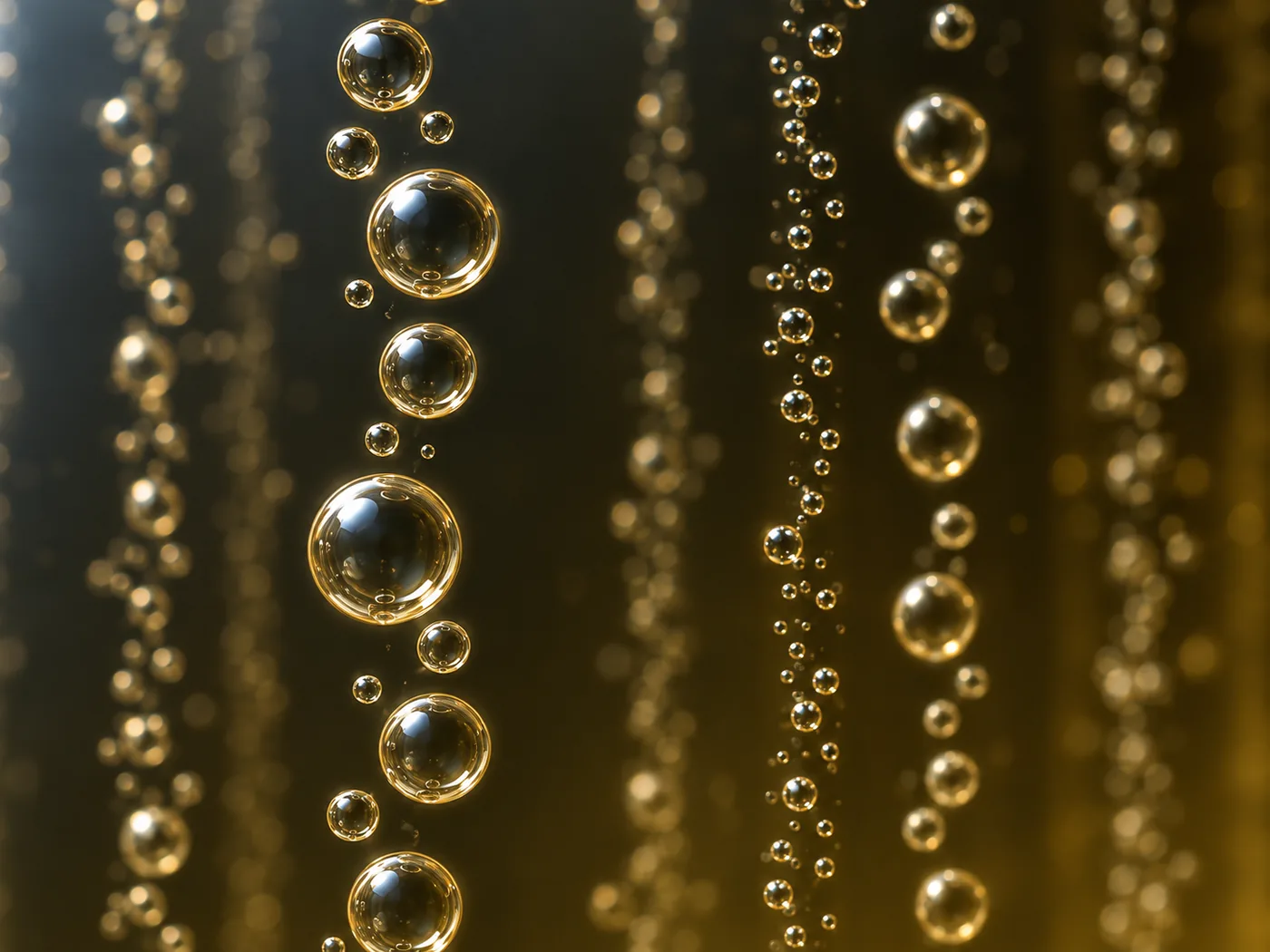
Hu and colleagues point out that the first commercial therapeutic protein made in recombinant animal cells (tPA; 1986 in their review) was produced by growing suspended CHO cells in a sparged stirred tank, and argue that the concern over “shear sensitivity” is at odds with industrial practiceSourced. At the same time, it has been reported that some cells from medical research (the human leukaemia cell line HL-60, prostate-derived cell lines and others) are clearly more sensitive to force than industrial cell linesSourced.
7. A materials engineer's view (1): bubble size is set by the holes and the surfactant
Put the pieces so far together and a contradiction appears.
- Dreher and colleagues report that a micro-sparger with 0.15 mm holes can raise kLa substantially compared with 0.8 mm holesSourced
- Hu and colleagues, on the other hand, report that the maximum EDR when a bubble bursts is larger the smaller the bubbleSourced
In short, small bubbles dissolve oxygen well but burst violently. Smaller bubbles increase the interfacial area per unit volume a, raising kLa, and at the same time raise the severity of the damage each bubble does when it bursts at the surface. Designers are handling both sides of the same gas-liquid interface at once (our commentary).
There are two ways to control that interface, and both are about materials.
- The holes in the sparger: drilled holes or fine pores; their size sets the initial bubble size
- Polymers dissolved in the medium: Hu and colleagues note that Pluronic F-68, polyvinyl alcohol (PVA), polyethylene glycol (PEG), dextran and methylcellulose have been tried as additives to soften bubble damageSourced, and explain that because the driving force of bubble bursting is a pressure difference, lowering the surface tension lowers the EDR overallSourced. In the experiments by Lemire and colleagues, Kolliphor P188 was added to the medium to bring total surfactant to 0.2% (w/v)Sourced
Hu and colleagues also cite a report that even at 10 million cells/mL with 1 g/L of PF-68 added, about 1,000 cells per bubble were trapped in the foam layer, and state that the protective effect may be limited at high cell concentrations or in long culturesSourced.
A surfactant is not an additive that solves the problem just by being there; it is a component whose benefit levels off at high cell density. Designing bubble formation (the material and machining of the sparger) separately from bubble bursting (the interfacial properties of the liquid) can be read as a field where the know-how of materials companies in defoaming, foaming and dispersion applies directly (our commentary).
8. A materials engineer's view (2): an adherent-culture system is a material surface
Suspension-culture equipment is sized in litres (volume), but equipment for adherent cells is described in square metres (area).
- Fixed bed: iCELLis confines carriers of 100% pure PET non-woven fibre in a bed, with small units of 0.5 to 4 m² and production units of 66 to 500 m²Sourced. The upper limit of the production units is 125 times that of the small unitsOur calculation (500 / 4)
- Hollow fibre: the Quantum system is described as having about 11,000 hollow fibres that give up to 21,000 cm² of growth surface after coating with a protein such as cryoprecipitateSourced. That is about 16.5 times the flat culture vessel (1,272 cm²) used for comparison in the same paperOur calculation (21,000 / 1,272)
What materials engineers should notice is that the “area” is the surface of fibres or membranes. Fibre diameter, porosity, surface treatment and the way proteins adsorb decide how cells attach and grow. As the words “after coating” in the hollow-fibre example indicate, cells do not attach to the bare polymer surface, so a layer of biological origin sits in between (our commentary).
In a fixed bed, the way the carriers are packed decides both the flow of medium (pressure drop, channelling) and how oxygen reaches the cells. The design of packed beds, filters and non-wovens is a classic problem of chemical engineering and fibre materials (our commentary).
9. What could not be confirmed, and open problems
(1) The current commercial scale of airlift reactors
The review says they are “used, but less common”Sourced, but the scale at which they are currently used in commercial production could not be confirmed in primary sources within the scope of this article, so it is not stated.
(2) Separating CO2 removal (pure oxygen in fine bubbles, air in large bubbles)
This is put forward by Hu and colleagues as “one possible solution”Not yet confirmed, and this article has not confirmed any primary source showing a track record at large scale.
(3) Shear “thresholds” differ between cells
For CHO cells and other industrial cell lines, it has been shown that lethal damage can be avoided at commercial scale, while some cells from medical research are more sensitiveSourced. Within the scope of this article, no single threshold could be confirmed that generalises to stirred culture of cells used in regenerative medicine and cell therapy (iPS cells and others).
(4) The numbers in this article are orders of magnitude
The required kLa (Fig. 4) and the EDR ratios (Fig. 5) are this article's calculationsOur calculation, not design values for any specific equipment, cell line or process.
- The stirred tank dominates, and suspension culture has been scaled up to around 10,000 L or moreSourced
- Systems for adherent cells (hollow fibre, fixed bed) scale by area. PET non-woven carriers and protein-coated hollow fibres are in useSourced
- Temperature, pH and dissolved oxygen are not independent. Through lactate, base and CO2 they are linked all the way to osmolalitySourced
- At 20 million cells/mL, a kLa of about 44 h⁻¹ is needed with air alone, or about 5 h⁻¹ with pure oxygenOur calculation
- Bubbles do more damage than impellers. Bursting bubbles reach 10⁷ to 10⁹ W/m³, orders of magnitude above the stirring averageSourced
- Small bubbles dissolve oxygen well but burst violently. Balancing the two is a job for materials: the sparger and the surfactant (our commentary)
10. Glossary
- Bioreactor
- A vessel and control system for growing cells in medium while controlling temperature, pH, dissolved oxygen and more.
- Stirred tank
- A tank in which a rotating impeller mixes the liquid, with gas sparged in from the bottom. The main type for suspension culture.
- Airlift
- A reactor with no impeller, in which rising bubbles circulate the liquid.
- Rocking (wave) bioreactor
- A platform holding a culture bag is rocked to mix by waves. Oxygen enters through the liquid surface.
- Hollow fibre / fixed bed
- Systems for adherent cells, which grow on the surfaces of a bundle of fine tubes or in a bed packed with carriers.
- Sparger
- The part that blows air, oxygen and CO2 into the liquid as bubbles from the bottom.
- Dissolved oxygen (DO)
- The amount of oxygen dissolved in the liquid, often expressed with equilibrium with air as 100%.
- kLa
- The volumetric oxygen transfer coefficient: the product of the liquid-side mass transfer coefficient kL and the interfacial area per unit volume a (h⁻¹).
- OUR / OTR
- Oxygen uptake rate / oxygen transfer rate. They balance at steady state.
- P/V
- Power input per unit volume (W/m³). The standard measure of how hard a tank is stirred.
- Energy dissipation rate (EDR)
- The rate at which turbulence turns energy into heat per unit volume. A yardstick for the forces on cells.
- Osmolality (mOsm/kg)
- The concentration of dissolved particles. Rises with base addition and CO2 accumulation.
- Respiratory quotient
- CO2 production rate divided by oxygen uptake rate. Reported to be close to 1 for CHO cells.
- Pluronic F-68
- A non-ionic polymeric surfactant added to media to soften bubble damage to cells.
11. References (primary sources)
- Varley J, Birch J “Reactor design for large scale suspension animal cell culture”, Cytotechnology 29:177–205 (1999) — pmc.ncbi.nlm.nih.gov
- Nienow AW “Reactor engineering in large scale animal cell culture”, Cytotechnology 50:9–33 (2006) — pmc.ncbi.nlm.nih.gov
- Hu W, Berdugo C, Chalmers JJ “The potential of hydrodynamic damage to animal cells of industrial relevance: current understanding”, Cytotechnology 63:445–460 (2011) — pmc.ncbi.nlm.nih.gov
- Singh V “Disposable bioreactor for cell culture using wave-induced agitation”, Cytotechnology 30:149–158 (1999) — pmc.ncbi.nlm.nih.gov
- Dreher T et al. (Sartorius Stedim Biotech) “Design space definition for a stirred single-use bioreactor family from 50 to 2000 L scale”, BMC Proceedings 7(Suppl 6):P55 (2013) — pmc.ncbi.nlm.nih.gov
- Li F et al. (Genentech) “Cell culture processes for monoclonal antibody production”, mAbs 2(5):466–479 (2010) — pmc.ncbi.nlm.nih.gov
- Lemire L et al. (Polytechnique Montréal / National Research Council Canada) “Scale-up of a monoclonal antibody CHO fed-batch production in stirred tank bioreactors: Effect of hydrodynamic conditions and feeding regimen”, Biotechnology Progress (January–February 2026 issue, doi:10.1002/btpr.70073) — pmc.ncbi.nlm.nih.gov
- Goudar CT, Piret JM, Konstantinov KB “Estimating cell specific oxygen uptake and carbon dioxide production rates for mammalian cells in perfusion culture”, Biotechnology Progress 27(5):1347–1357 (2011) (PubMed abstract) — pubmed.ncbi.nlm.nih.gov
- Kim J et al. (PBS Biotech) “Measurement of Oxygen Transfer Rate and Specific Oxygen Uptake Rate of h-iPSC Aggregates in Vertical Wheel Bioreactors to Predict Maximum Cell Density Before Oxygen Limitation”, Bioengineering 12(4):332 (2025) — pmc.ncbi.nlm.nih.gov
- Lennaertz A et al. (ATMI LifeSciences) “Viral vector production in the integrity iCELLis single-use fixed-bed bioreactor, from bench-scale to industrial scale”, BMC Proceedings 7(Suppl 6):P59 (2013) — pmc.ncbi.nlm.nih.gov
- Jakl V et al. “A novel approach for large-scale manufacturing of small extracellular vesicles from bone marrow-derived mesenchymal stromal cells using a hollow fiber bioreactor”, Frontiers in Bioengineering and Biotechnology 11:1107055 (2023) — frontiersin.org
12. Claim-to-source audit
| Claim in the text | Basis | Label |
|---|---|---|
| That the most commonly used reactor type is the stirred tank, and airlift reactors are also used but less common; and that no guidance specific to large-scale animal cell culture above 10,000 L has been published | Varley & Birch 1999 review (abstract). Reference 1 https://pmc.ncbi.nlm.nih.gov/articles/PMC3463394/ | Sourced |
| That “shear sensitivity” from agitation and bursting bubbles is no longer regarded as a major problem, yet the perception still influences development at commercial scale. That the high densities of fed-batch culture led to the use of oxygen and oxygen-enriched air, so that the rate of CO2 evolution affects pH control, pCO2 and osmolality. That much of the problem would disappear if the oxygen transfer could be achieved with more vigorous aeration and agitation | Nienow 2006 review (abstract). Reference 2 https://pmc.ncbi.nlm.nih.gov/articles/PMC3476006/ | Sourced |
| That suspension culture is routinely scaled up to around 10,000 L or more. That animal cells are larger than microbes and have no cell wall. The definition of EDR; that P/V is a whole-tank average and local values near the impeller are orders of magnitude higher. That the bursting of 1 to 2 mm bubbles reaches a maximum EDR of 10⁷ to 10⁹ W/m³, higher for smaller bubbles. That most damage occurs where bubbles disengage at the surface. That one 3.5 mm bubble killed on average 1,050 insect cells. That with NS0 cells damage progressed above a sparger outlet velocity of 30 m/s. That glycosylation changes were reported at 6 × 10⁴ W/m³ or more, well above typical commercial operating conditions. That 3 × 10⁷ W/m³ reproduced the performance loss of a large centrifuge. That the first commercial therapeutic protein from recombinant animal cells (tPA, 1986) was made with suspended CHO cells in a sparged stirred tank. That PF-68, PVA, PEG, dextran and methylcellulose have been tried; that lowering surface tension lowers EDR; that even at 10 million cells/mL with 1 g/L PF-68 about 1,000 cells per bubble were trapped in the foam layer; and that protection may be limited at high concentration or over long periods. That HL-60 and others are more sensitive. The proposal to separate CO2 removal, with pure oxygen in fine bubbles and air in large bubbles | Hu, Berdugo & Chalmers 2011 review. Reference 3 https://pmc.ncbi.nlm.nih.gov/articles/PMC3176934/ | Sourced |
| That the rocking type mixes with waves raised by rocking and achieves good oxygen transfer without damaging shear or bubbles. That it was demonstrated up to 100 L of culture and, being disposable, needs no cleaning or sterilisation. That this includes an example of 293 cells cultured on microcarriers | Singh 1999 (abstract). Reference 4 https://pmc.ncbi.nlm.nih.gov/articles/PMC3449934/ | Sourced |
| The configuration of 50 to 2,000 L single-use stirred tanks (cylindrical, two impellers on a rigid shaft, submerged sparger, H/D 2:1, impeller/tank diameter 0.38, a sparger combining 0.8 mm and 0.15 mm holes). The design ranges for a CHO process peaking at 27 to 28 million cells/mL (tip speed below 2.0 m/s, kLa above 7 h⁻¹ with pure oxygen, mixing time below 60 s, P/V 10 to 250 W/m³). That mixing times below 30 s were achieved at every scale. That the micro holes can raise kLa substantially | Dreher et al. 2013 conference paper. Reference 5 https://pmc.ncbi.nlm.nih.gov/articles/PMC3980816/ | Sourced |
| That stainless-steel tanks have dominated large-scale manufacturing (1,000 to more than 25,000 L). That temperature is often lowered from 37 °C to 30 to 35 °C 48 hours after inoculation. That a pH deviation of just 0.1 can affect growth and metabolism. That DO is normally set at 20 to 50% of air saturation. The chain of lactate accumulation, pH fall, base addition and rising osmolality. That media are designed for an osmolality of 270 to 330 mOsm/kg | Li et al. 2010 review. Reference 6 https://pmc.ncbi.nlm.nih.gov/articles/PMC2958569/ | Sourced |
| That CHO cells are the established workhorse for producing antibodies and other therapeutic proteins. That pH 7.0 ± 0.2 was held with CO2 sparging and sodium hydroxide and bicarbonate. The DO set point of 60% and cascade aeration. That Kolliphor P188 was added to bring total surfactant to 0.2% (w/v). That tip speeds below 1 m/s and P/V of 10 to 80 W/m³ are typical in small vessels, and that the maximum P/V in large single-use tanks is around 20 to 30 W/m³ | Lemire et al. 2026 original paper. Reference 7 https://pmc.ncbi.nlm.nih.gov/articles/PMC12908111/ | Sourced |
| That CHO oxygen uptake is 5.14 to 5.77 pmol/cell/day under standard conditions (DO 50%, pH 6.8, 36.5 °C) with a respiratory quotient of 0.98 to 1.14; and 3.97 pmol/cell/day at 30.5 °C | Goudar et al. 2011 (PubMed abstract). Reference 8 https://pubmed.ncbi.nlm.nih.gov/21626724/ | Sourced |
| The equations OUR = OTR and oxygen uptake per cell × cell density = kLa × (C* − C). The use of 0.21 mmol/L at 37 °C with air and about 1 mmol/L with pure oxygen (about 476%). That kLa of 0.438 h⁻¹ was measured at 3 L and 30 rpm, and the maximum density before oxygen limitation calculated as 4.65 million cells/mL | Kim et al. 2025 original paper. Reference 9 https://pmc.ncbi.nlm.nih.gov/articles/PMC12024368/ | Sourced |
| That iCELLis uses carriers of 100% pure PET non-woven fibre in a fixed bed; small units 0.5 to 4 m², production units 66 to 500 m² | Lennaertz et al. 2013 conference paper. Reference 10 https://pmc.ncbi.nlm.nih.gov/articles/PMC3980326/ | Sourced |
| That the Quantum system consists of about 11,000 hollow fibres giving up to 21,000 cm² of growth surface after protein coating; and that the flat culture vessel used for comparison is 1,272 cm² | Jakl et al. 2023 original paper. Reference 11 https://www.frontiersin.org/journals/bioengineering-and-biotechnology/articles/10.3389/fbioe.2023.1107055/full | Sourced |
| Required kLa (at 10, 20 and 30 million cells/mL: 21.8, 43.6 and 65.5 h⁻¹ with air alone, 2.6, 5.1 and 7.7 h⁻¹ with pure oxygen; about 7.2 h⁻¹ at 28 million cells/mL with pure oxygen). About 1/8.5 with pure oxygen. Surface-aeration kLa about a sixteenth of the design target. The EDR ratios (about 240 times and about 40,000 times). The fixed-bed area ratio of 125 times. The hollow-fibre area equal to about 16.5 flat vessels. That the dissolved oxygen would be used up in about 1.4 minutes | Our calculation. Oxygen uptake of 5.5 pmol/cell/day, C* (air 0.21, pure oxygen 1.0 mmol/L) and a DO set point of 50% are assumptions set by this article. The comparison sets values from different studies side by side and is not a design value for any specific equipment | Our calculation |
| The practicality of separating CO2 removal, with pure oxygen in fine bubbles and air in large bubbles. Nienow's outlook that more vigorous aeration and agitation would make most of the problem disappear | Both are proposals or outlooks in the papers; no primary source showing a track record at large scale was confirmed within the scope of this article. Reference 3 https://pmc.ncbi.nlm.nih.gov/articles/PMC3176934/ | Not yet confirmed |
| The current commercial scale of airlift reactors; a shear threshold that generalises to cells for regenerative medicine | Not stated because they could not be confirmed in primary sources within the scope of this article (commentary) | Commentary |
| The reading that the real constraints are oxygen, CO2 and mixing. Grouping the types into suspension and adherent. The point that the more efficiently oxygen is added, the more a separate way of removing CO2 is needed. The two sides of small bubbles. The reading that surfactants are components whose benefit levels off at high density. The framing that adherent-culture systems scale by area and are material surfaces. The general statements that bottom-driven units exist, that kLa = kL × a, and that Pluronic F-68 is a non-ionic polymeric surfactant | This article's own framing and commentary based on published content. Not views expressed by the authors of the papers | Commentary |
| That Figs. 1 to 5 are explanatory drawings, not real equipment or measurement results; and that the hero image and Fig. 6 are AI-generated images | A note by this article (commentary) | Commentary |
Last updated 23 September 2026. Sources are limited to primary material (peer-reviewed papers and conference papers in PubMed Central and elsewhere, and PubMed abstracts). Papers by researchers at equipment makers (Refs. 5, 9 and 10) are treated as statements about that company's own equipment. The current commercial scale of airlift reactors, a large-scale track record for separated CO2 removal, and shear thresholds for cells used in regenerative medicine are not covered, because they could not be confirmed in published primary sources. All figures are explanatory concept graphics. Figs. 1 to 5 are vector drawings; the hero image and Fig. 6 are AI-generated images, and none of them shows real equipment, a real product or an actual culture.