TECHNOLOGY EXPLAINER
Solution Coating
— a perovskite film is made or broken by how it dries
The light-absorbing layer of a perovskite solar cell can be made simply by coating a solution and letting it dry. But spin coating, the method behind most record lab efficiencies, throws away more than 90% of the ink, and it does not carry over to large areas as it is. Change the way you coat, and you change the way the crystals form. This article sorts out coating methods, inks, solvents and crystallisation control from a materials engineer's point of view.

- What solution coating is, in three points
- Four ways to coat: spin, blade, slot-die and inkjet
- Controlling crystallisation: when and where supersaturation happens
- A materials engineer's view (1): the ink is not a solution but a piece of coordination chemistry
- Choosing solvents: ones that coordinate, and ones that leave quickly
- Scaling up: antisolvent baths, gas flow and vacuum
- A materials engineer's view (2): a few tens of ppm of surfactant changes the coating
- Our calculation: coating speed, output and the solvent to be evaporated
- A materials engineer's view (3): solvents are also regulated substances
- Open problems, and what this article could not confirm
- Glossary / References / Claim-to-source audit
Sourced = stated in published material or a peer-reviewed paper (link given)
Our calculation = a value this article derived from assumptions it states
Not yet confirmed = a plan, target or outlook with no confirmed track record
Structural readings and materials or process interpretations are marked separately as Commentary.
1. What solution coating is, in three points
Solution coating means spreading a liquid in which the perovskite raw materials are dissolved (the precursor ink) onto a substrate, then driving off the solvent to leave a crystalline film. One reason this material attracted so much attention is that the absorber can be made without the high-temperature crystal growth or high-vacuum equipment that silicon solar cells require.
- What is happening: as the solvent leaves, the solute becomes supersaturated, nuclei form and crystals grow. The aim is to make that sequence happen uniformly across the whole film. The NREL review explains that uncontrolled drying makes crystals grow unevenly into a dendritic (branching) morphology that fails to cover the substrate and creates shunt paths in the cellSourced
- The lab standard: spin coating is the most common deposition method, but it is described as generally limited to substrates under about 4 inches, with most of the precursor ink (more than 90%) wastedSourced
- Methods for manufacturing: blade coating, slot-die coating, spray coating, inkjet printing and screen printing are all being studied, with roll-to-roll (R2R) production in viewSourced
What decides the quality of a perovskite film is less the coating tool than how the solvent is removed. The NREL review notes that in spin coating it is the centrifugal force of rotation that makes the wet film thin and flat; those conditions are hard to reproduce with other coating methods, and there is no simple way to transfer spin-coating conditions directly to a large-area methodSourced. In other words, every change of coating method means redesigning the drying and the crystallisation from scratch (our commentary).
2. Four ways to coat: spin, blade, slot-die and inkjet
| Method | How it works | Strengths and weaknesses cited in the review |
|---|---|---|
| Spin coating | The substrate is spun and centrifugal force thins the liquid | The most common method, but generally limited to under about 4 inches, with more than 90% of the ink wasted. Mini-modules of up to about 10 × 10 cm² can be made, but their efficiency is well below that of small-area devices |
| Blade coating | A blade drags the liquid across the substrate | Film thickness is set by ink concentration, the gap between blade and substrate, and blade speed. Fixing the blade and moving the substrate makes it R2R-compatible. Far less ink is wasted than in spin coating |
| Slot-die coating | A fixed volume is delivered through a narrow slit in the head | Liquid flow is easy to control, but more ink is needed to fill the tank and lines, so it is ill-suited to formulation development. Once the ink is settled, yield and reproducibility are better than with a blade |
| Inkjet printing | Droplets are ejected from nozzles | Droplet size and placement can be finely controlled, and it excels at patterning. But coating a large area takes a very long time |
All Sourced (NREL, Li et al. 2018 [Reference 1]). The same review points out that blade and slot-die coating both spread the wet film with a moving meniscus (the liquid edge).
In slot-die coating, thickness is set by how much you pump
Slot-die coating is a pre-metered method: all the liquid pumped to the head ends up in the film. The NREL review by Park and Zhu summarises that the final film thickness is proportional to the flow rate and the solids concentration, and inversely proportional to the substrate (web) speed, the coating width and the density of the dry filmSourced. The review also notes that slot-die coating was invented by Beguin of Eastman Kodak in 1951, and that it was first applied to perovskites in 2015Sourced.
A 2015 report (Hwang et al.) described cells in which every layer except the electrodes was printed by slot-die coating, reaching a power conversion efficiency of up to 11.96%, and showed that the process could be used for R2R productionSourced.
In blade coating, thickness responds to speed in opposite directions
Blade coating has a distinctive behaviour pointed out in the Park and Zhu review. At low speed, solvent evaporates at the meniscus and the solids gather near the contact line, so the faster you go the thinner the film (the evaporation regime). At high speed, viscous drag pulls out a wet film that dries afterwards, so the faster you go the thicker the film (the Landau–Levich regime)Sourced. On the same machine, the rule governing thickness flips depending on the speed range.
In inkjet printing, thickness is set by drop spacing
In 2018 Mathies and colleagues at KIT (Karlsruhe Institute of Technology) inkjet-printed a triple-cation perovskite containing 10% Cs, reporting that film thickness could be controlled between 175 and 780 nm simply by changing the drop spacing. They reported a power conversion efficiency of 12.9% for stabilised output at constant voltageSourced. Because the pattern is laid down digitally, the method suits products with free-form shapes or applications where appearance matters (our commentary).
3. Controlling crystallisation: when and where supersaturation happens
The NREL review divides the ways of avoiding the dendritic morphology that becomes a problem at large area into two groups: physical methods that promote supersaturation, and chemical additives that retard crystal growthSourced. The logic runs like this: remove the solvent fast → supersaturation rises sharply → many nuclei form, and no single nucleus has time to grow large → the film comes out flat and denseSourced.
(1) Antisolvent dripping: the turning point of 2014
Partway through spin coating, a solvent that does not dissolve perovskite (an antisolvent) is dripped on to make the film precipitate all at once. Two groups reported the method almost simultaneously in 2014.
- Jeon et al. (Nature Materials): coated from a mixed solvent of γ-butyrolactone (GBL) and dimethyl sulfoxide (DMSO) and dripped toluene on. Passing through a CH3NH3I–PbI2–DMSO intermediate phase, the process gave extremely uniform, dense films and a certified efficiency of 16.2% with no hysteresisSourced
- Xiao et al. (Angewandte Chemie): exposed a spin-coated DMF solution of CH3NH3PbI3 to chlorobenzene immediately after coating to induce crystallisation. The flat films consisted of large, micron-scale grains, and the authors reported an average of 13.9 ± 0.7% and a steady-state efficiency of 13%Sourced
The NREL review gives the requirement for an antisolvent as being miscible with the precursor solvents (DMF, DMSO, GBL and so on) while barely dissolving the perovskite itself, and lists toluene, chlorobenzene, ethyl ether, ethyl acetate, hexane and anisole as examplesSourced.
(2) Gas quenching: blowing dry gas across the film
Instead of an antisolvent, a stream of nitrogen or another gas strips the solvent off rapidly. The NREL review notes reports of gas flow speeding up crystallisation during spin coating, and examples where this was carried over to slot-die coating with an air knife to assist dryingSourced.
In 2023 Geistert and colleagues at KIT aimed an inclined slit nozzle delivering nitrogen at slot-die-coated wet films and refined the conditions while watching the drying in situ with a camera. They showed how to adjust the nozzle to prevent gas backflow, and reported up to 18.6% for cells, 17.2% for a 50 × 50 mm² mini-module, and only very small losses when scaling up the areaSourced. Gas quenching, in other words, is a step in which gas flow strength, drying rate and the position where crystallisation begins decide the film morphology.
(3) Vacuum flash: a sudden drop in pressure
In 2016 Li and colleagues at EPFL (the Swiss Federal Institute of Technology in Lausanne) reported in Science a "vacuum flash" in which the freshly coated substrate is suddenly exposed to reduced pressure to pull the solvent out. They achieved a best of 20.5% and a certified 19.6% for cells with an aperture area above 1 cm², noting that the previous certified record for comparable areas had been 15.6%Sourced.
(4) Two-step deposition: PbI2 first, organic salt second
In 2013 Burschka et al. (Nature) used sequential deposition, first loading PbI2 into nanoporous TiO2 and then converting it by exposure to a CH3NH3I solution, improving morphological control and reproducibility and reaching an efficiency of about 15%Sourced. The NREL review cites as advantages of the two-step method that uniform PbI2 films are relatively easy to make over large areas, and the volume expansion on conversion to perovskite fills pinholes, and says the method is widely used with slot-die coating, electrodeposition and spray coatingSourced.
4. A materials engineer's view (1): the ink is not a solution but a piece of coordination chemistry
The 2015 formulation by Ahn et al. (JACS) captures the way this field thinks. PbI2, CH3NH3I and DMSO are dissolved in DMF at a 1:1:1 molar ratio. DMSO is not there as a solvent: it is added in stoichiometric amount as a ligand to coordinate to PbI2Sourced.
- In the infrared spectrum the S=O stretch shifts from 1045 cm⁻¹ (DMSO alone) to 1020 cm⁻¹ after reaction with PbI2, and to 1015 cm⁻¹ after reaction with PbI2 plus CH3NH3I, showing that an adduct of a Lewis base (DMSO) and a Lewis acid (PbI2) has formedSourced
- Spin coating gives a transparent adduct film, and heating at 65 °C for 1 minute drives off the volatile DMSO and turns it into dark-brown perovskiteSourced
- High reproducibility was reported, with an average of 18.3% and a best of 19.7% across 41 cellsSourced
The Park and Zhu review adds that besides DMSO, thiourea, pyridine and NMP can also serve as Lewis bases that form adducts through the lone pairs on sulfur, nitrogen and oxygenSourced. The NREL review by Li et al. likewise explains that forming Lewis acid-base pairs raises the solubility of lead halides and slows nucleation and crystal growthSourced.
So this ink is not simply "something dissolved in a liquid" but a precursor designed to become an intermediate solid first, then turn into the target crystal as the ligand is removed. Coordination strength, volatility, the volume change as the ligand leaves: all of these are worked out with coordination chemistry and thermal analysis, and it is an area where engineers who have handled complex and metal-salt precursors can put their experience straight to use (our commentary).
5. Choosing solvents: ones that coordinate, and ones that leave quickly
When you try to coat large areas fast, solvent choice sets the upper limit on coating speed. The framework laid out in 2019 by Deng and colleagues at the University of North Carolina (Science Advances) makes this easy to see.
- DMSO and DMF coordinate strongly to Pb²⁺, so they dissolve PbI2, but they dry slowly at room temperature. Even with high-speed blade coating the wet film stays wet, and it takes minutes to tens of minutes to dry and crystalliseSourced
- 2-methoxyethanol (2-ME) and acetonitrile (ACN) evaporate easily and barely coordinate to Pb²⁺. On their own, however, they give films with poor crystallinity and poor adhesion to the substrateSourced
- The answer was to use the volatile, non-coordinating solvent as the main solvent and add a small amount of the less volatile, coordinating solvent (DMSO). This achieved both fast drying and large grains at room temperatureSourced
With this formulation, Deng and colleagues blade-coated in ambient air at room temperature at 99 mm/s, obtaining a certified efficiency of 16.4% for a module with an aperture area of 63.7 cm²Sourced. The paper also records that drying was accelerated right after coating with a nitrogen knife (a stream of nitrogen applied at a set distance behind the blade), and that coating faster than 10 mm/s leaves a wet film a few micrometres thickSourced.
6. Scaling up: antisolvent baths, gas flow and vacuum
What gets in the way when a technique developed on spin coating is moved to large areas? Here are the key points from the NREL reviewSourced.
| Issue | What the review says | How it is handled at large area |
|---|---|---|
| Antisolvent dripping | Dripping or spraying is used only with spin coating, and it produces complex behaviour across the whole substrate | An antisolvent bath, in which the wet film is briefly immersed, has no limit on substrate size and can be built into R2R |
| Processing window | At large area the solvent dries before the antisolvent can be applied, so the window is easily missed | Drying is slowed with DMSO-containing solvent mixtures. An NMP and DMF mixture extended the drying time to as much as about 8 minutes, making it possible to use an antisolvent bath after blade coating (up to 20 cm²) |
| Annealing time | Usually takes 5 to 120 minutes; long times would make an R2R line impractically long | An example of cutting it from over 10 minutes to under 1 minute by adjusting the precursor chemistry. Near-infrared and flash-light heating are also being studied |
| Substrate heating | Heating speeds up solvent evaporation | Substrate heating is relatively easy even at large area, and is used with blade, spray and dip coating, among others |
All Sourced (NREL, Li et al. 2018 [Reference 1]). The Park and Zhu review [Reference 2] also cites a report that, in slot-die coating, single-step coating onto a substrate preheated to about 65 °C followed by a cool air stream worked better than other conditions.
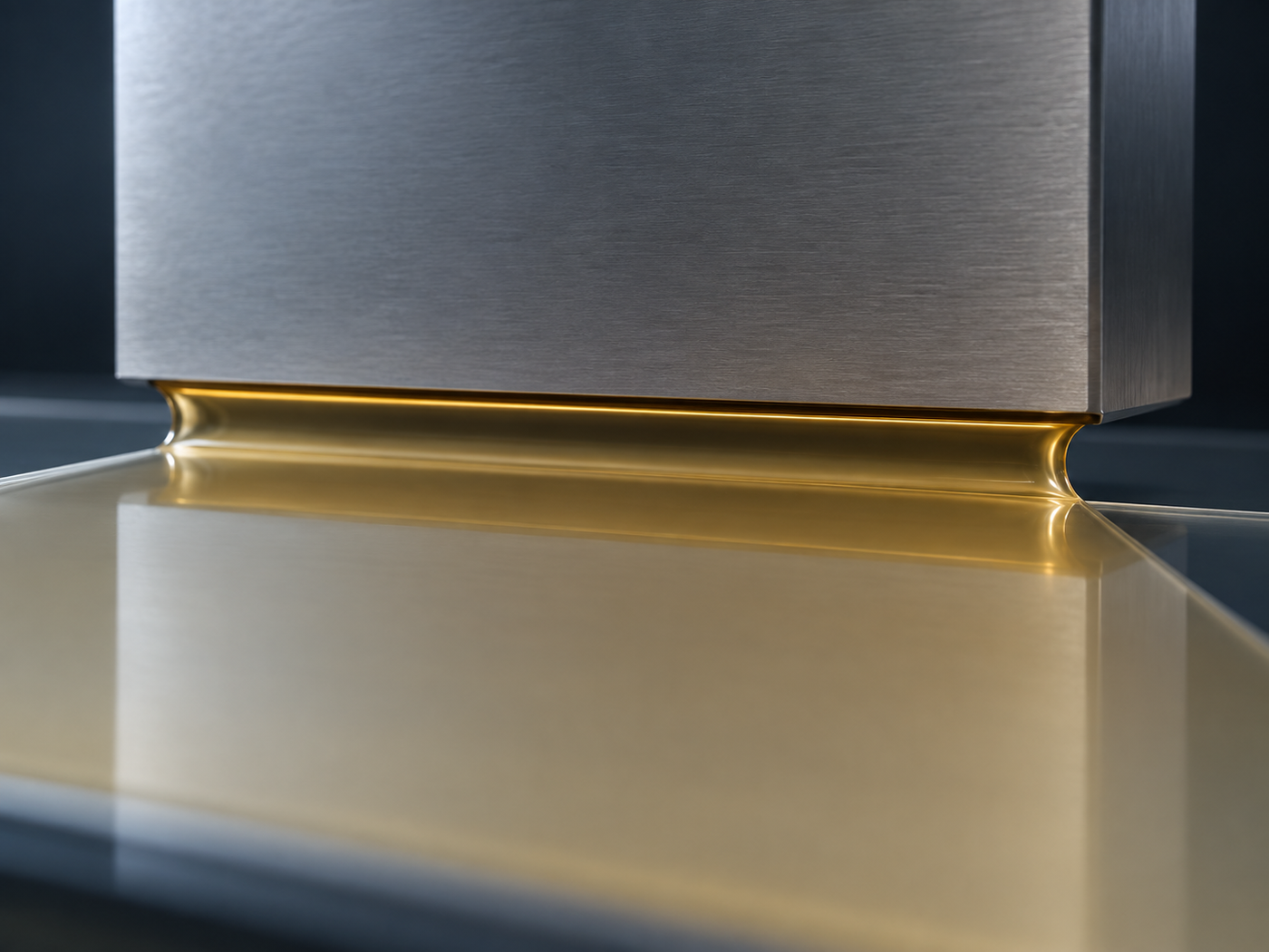
7. A materials engineer's view (2): a few tens of ppm of surfactant changes the coating
In 2018 Deng et al. (Nature Energy) reported that adding a tiny amount (a few tens of ppm) of surfactant (for example L-α-phosphatidylcholine) to a perovskite ink dramatically changes the fluid behaviour during drying and improves the ink's adhesion to non-wetting charge transport layersSourced.
- Blade coating at 180 m/h gave smooth films with a root-mean-square roughness of 14.5 nm over 1 cmSourced
- The surfactant also passivated charge traps, giving over 20% in small-area cellsSourced
- High-speed coating in ambient air gave stabilised module efficiencies of 15.3% at an aperture area of 33.0 cm² and 14.6% at 57.2 cm²Sourced
The Park and Zhu review summarises that in blade coating, evaporation and convection at the meniscus and the Marangoni effect govern film thicknessSourced.
To anyone who works on paints, adhesives or film coatings, "a trace of surfactant changes levelling and dewetting" is a familiar phenomenon. What is new with perovskites is that it worked not only on film smoothness but also, at the same time, on defect passivation, that is, on electrical properties. Put the other way round, change one additive and both coatability and photovoltaic performance move together. This is a material where it is hard to optimise coating conditions and design the material in separate departments (our commentary).
8. Our calculation: coating speed, output and the solvent to be evaporated
Citing Deng et al. 2018, the Park and Zhu review states that a coating speed of 180 m/h would give a production capacity of 236 MW a year on a line 1 m wideSourced. Let us check what assumptions lie behind that figure.
Assumptions (all set by this article)Our calculation
- Coating width 1 m, running all 8,760 hours of the year (no stoppages, changeovers or rejects)
- Module efficiency 15%, standard test condition irradiance of 1,000 W/m²
Calculation
- 180 m/h × 1 m × 8,760 h = 1,576,800 m² a year
- 1,576,800 m² × 1,000 W/m² × 0.15 = 236,520,000 W, or about 237 MW a year
The review's 236 MW can be reproduced almost exactly with these assumptions (15% efficiency, continuous operation).
Applying the same assumptions to the 99 mm/s of Deng et al. 2019: 99 mm/s = 356.4 m/h → 356.4 × 8,760 = 3,122,064 m² → at 15% efficiency, about 468 MW a yearOur calculation.
Assumptions and limits: a real factory does not run continuously, part of the area becomes inactive scribe lines and edges, and there are yield losses. This calculation also covers only the coating speed of the single perovskite layer. If other steps such as the charge transport layers, electrodes, scribing or encapsulation become the bottleneck, the capacity of the whole line will be smaller still. The calculation is meant to show what order of output a coating speed corresponds to; it does not describe the capacity of any particular factory.
Assumptions (set by this article)Our calculation
- The wet film just after coating, described by Deng et al. 2019 as "a few micrometres", is taken as 5 µm
- Almost all of the wet-film volume is taken to be solvent, all of which evaporates on drying (the volume of solids is ignored)
Calculation
- 5 µm × 1 m² = 5 × 10⁻⁶ m³ = about 5 mL per m²
- Coating continuously at 1 m wide and 99 mm/s (356.4 m²/h) means evaporating 5 mL × 356.4 = about 1.8 L of solvent an hour in the drying zone
Assumptions and limits: wet-film thickness varies with coating speed, ink concentration and gap; 5 µm is an assumption that pins "a few micrometres" to a single value. The calculation is meant to show, as an order of magnitude, that equipment to capture and exhaust litres of solvent an hour is needed right behind the coater.
9. A materials engineer's view (3): solvents are also regulated substances
N,N-dimethylformamide (DMF), long a workhorse solvent for perovskite inks, is classified in the EU as, among other things, toxic for reproduction, Category 1B. A 2021 EU regulation (an amendment to Annex XVII of REACH) requires that from 12 December 2023, anyone manufacturing or using DMF at a concentration of 0.3% or more take measures to keep worker exposure below the derived no-effect levels (DNELs) of 6 mg/m³ by inhalation and 1.1 mg/kg/day by the dermal routeSourced.
Recognising that polyurethane coatings and membranes and synthetic fibre production would need longer to comply with the DNELs, the regulation defers application to 12 December 2024 for polyurethane coating and membrane manufacture on textiles and paper, and to 12 December 2025 for synthetic fibre spinningSourced. In short, DMF is a solvent whose use the coating, membrane and fibre industries have already moved on to managing under controls.
As Section 5 showed, one route in solvent design for faster coating is to replace DMF and DMSO as the main solvent with 2-ME or ACNSourced. But changing the solvent also changes the regulatory, exhaust and recovery requirements. If a single line evaporates litres of solvent an hour, as in the calculation in Section 8, solvent selection becomes a design problem with four conditions to meet at once: film quality, coating speed, working environment and recovery equipment (our commentary). This article has not looked into where each alternative solvent stands under regulation.
10. Open problems, and what this article could not confirm
(1) The best efficiencies still come from small spin-coated cells
The NREL review (2018) points out that mini-module efficiencies clearly lag behind the gains made in small-area cellsSourced. The Park and Zhu review (2020) likewise says that spin coating, used on small substrates (typically 2.5 × 2.5 cm), cannot be carried straight into commercialisation, and that materials and methods for large areas need to be developedSourced. The relationship between area and efficiency is covered in detail in our explainer on roll-to-roll processing and scale-up.
(2) Few devices are made with every layer coated
The NREL review says that most studies deposit only the absorber, or one or two layers, by scalable methods, and that reports of fully printed devices are few. It also notes that the back electrode is mainly made by vacuum evaporationSourced. Charge transport layer materials and their deposition are covered in our explainers on charge transport layers and cell architecture, and on self-assembled monolayers.
(3) Actual coating conditions on production lines
Which coating methods, solvents and drying methods are used on actual production or pilot lines could not be confirmed from companies' primary sources within the scope of this article, so they are not stated. Company developments are covered in our company profilesNot yet confirmed.
(4) Efficiencies in papers are not measured on the same basis
The efficiencies quoted in this article differ from paper to paper in whether they are cells or modules, in area, in whether they are certified, and in whether they are steady-state or scanned. For example, 16.2% (Jeon et al.), 19.6% (Li et al.) and the 16.4% module (Deng et al. 2019) are certified values, while 18.3% and 19.7% (Ahn et al.) and 15.3% (Deng et al. 2018) were measured within the papersSourced. Lining the numbers up does not tell you which method is better. Differences in measurement conditions are covered in our explainer on conversion efficiency and performance metrics.
| Report | Method | Area and device type | Efficiency | Certification |
|---|---|---|---|---|
| Jeon et al. 2014 | Spin plus toluene drip | Small-area cell | 16.2% | Certified |
| Xiao et al. 2014 | Spin plus chlorobenzene | Small-area cell | 13.9% average | Measured in the paper |
| Ahn et al. 2015 | Lewis base adduct | Small-area cells (41) | 18.3% average, 19.7% best | Measured in the paper |
| Li et al. 2016 | Vacuum flash | Cell with aperture above 1 cm² | 20.5% best, 19.6% | 19.6% certified |
| Deng et al. 2018 | Blade plus surfactant | Module, 33.0 cm² | 15.3% (stabilised) | Measured in the paper |
| Deng et al. 2019 | Blade plus solvent design | Module, 63.7 cm² | 16.4% | Certified |
| Geistert et al. 2023 | Slot-die plus gas quench | Mini-module, 50 × 50 mm² | 17.2% | Not stated in the abstract |
All Sourced (abstracts of each paper [References 3, 4, 5, 7, 8, 9 and 11]). Lining them up in a table is this article's own arrangement; it is not a comparison under identical conditions.
- Spin coating is generally limited to under about 4 inches and throws away more than 90% of the inkSourced
- Film quality is decided by how the solvent is removed. The basic approach is to raise supersaturation sharply with antisolvents, gas flow, reduced pressure or heat, so that many nuclei formSourced
- The ink is a piece of coordination chemistry. DMSO is coordinated to PbI2 in stoichiometric amount, and the film crystallises via an intermediateSourced
- Combining solvent volatility and coordination strength has taken blade coating up to 99 mm/sSourced
- A few tens of ppm of surfactant improves both coatability and defect passivationSourced
- At 1 m wide and 180 m/h, the continuous-operation ceiling is about 237 MW a year. Solvent has to be driven off at litres an hourOur calculation
11. Glossary
- Precursor ink
- A liquid in which the perovskite raw materials (lead halides plus organic and inorganic cation salts, for example) are dissolved in a solvent.
- Supersaturation
- A state in which a liquid holds more solute than it can normally dissolve. The higher it is, the more readily nuclei form.
- Nucleation
- The formation of the first tiny seeds of a crystal within a liquid.
- Antisolvent
- A solvent that barely dissolves the target substance. Added to a wet film, it makes the substance precipitate all at once.
- Gas quenching
- Crystallising a film by blowing dry gas over the wet film to drive off the solvent rapidly.
- Lewis base adduct
- An intermediate formed when an electron-pair donor such as DMSO coordinates to a lead halide.
- Slot-die coating
- A pre-metered method in which pumped liquid is delivered through a narrow slit.
- Blade coating
- A method in which a blade drags the liquid across the substrate. Thickness varies with the blade-substrate gap and the speed.
- Meniscus
- The liquid edge formed between the coating head and the substrate. Flow and evaporation here decide the film.
- Marangoni effect
- Liquid flow driven by differences in surface tension. A cause of uneven thickness during drying.
- R2R (roll-to-roll)
- A production method in which a rolled substrate is unwound, coated continuously and wound up again.
- DNEL
- Derived no-effect level. Under the EU's REACH regulation, the level below which exposure should be kept.
12. References (primary sources)
- Li Z, Klein TR, Kim DH, Yang M, Berry JJ, van Hest MFAM, Zhu K (NREL) “Scalable fabrication of perovskite solar cells”, Nature Reviews Materials 3, 18017 (2018) (DOE Public Access accepted manuscript) https://www.osti.gov/servlets/purl/1430821
- Park NG, Zhu K “Scalable fabrication and coating methods for perovskite solar cells and solar modules”, Nature Reviews Materials 5, 333–350 (2020) (DOE Public Access accepted manuscript) https://www.osti.gov/servlets/purl/1605079
- Jeon NJ et al. “Solvent engineering for high-performance inorganic–organic hybrid perovskite solar cells”, Nature Materials 13, 897–903 (2014) https://doi.org/10.1038/nmat4014
- Xiao M et al. “A Fast Deposition-Crystallization Procedure for Highly Efficient Lead Iodide Perovskite Thin-Film Solar Cells”, Angewandte Chemie International Edition 53, 9898–9903 (2014) https://doi.org/10.1002/anie.201405334
- Ahn N et al. “Highly Reproducible Perovskite Solar Cells with Average Efficiency of 18.3% and Best Efficiency of 19.7% Fabricated via Lewis Base Adduct of Lead(II) Iodide”, Journal of the American Chemical Society 137, 8696–8699 (2015) https://doi.org/10.1021/jacs.5b04930
- Burschka J et al. “Sequential deposition as a route to high-performance perovskite-sensitized solar cells”, Nature 499, 316–319 (2013) https://doi.org/10.1038/nature12340
- Li X et al. “A vacuum flash–assisted solution process for high-efficiency large-area perovskite solar cells”, Science 353, 58–62 (2016) https://doi.org/10.1126/science.aaf8060
- Deng Y et al. “Surfactant-controlled ink drying enables high-speed deposition of perovskite films for efficient photovoltaic modules”, Nature Energy 3, 560–566 (2018) https://doi.org/10.1038/s41560-018-0153-9
- Deng Y et al. “Tailoring solvent coordination for high-speed, room-temperature blading of perovskite photovoltaic films”, Science Advances 5, eaax7537 (2019) (full text on PMC) https://pmc.ncbi.nlm.nih.gov/articles/PMC6897546/
- Hwang K et al. “Toward Large Scale Roll-to-Roll Production of Fully Printed Perovskite Solar Cells”, Advanced Materials 27, 1241–1247 (2015) https://doi.org/10.1002/adma.201404598
- Geistert K et al. (KIT) “Controlling Thin Film Morphology Formation during Gas Quenching of Slot-Die Coated Perovskite Solar Modules”, ACS Applied Materials & Interfaces (2023) https://doi.org/10.1021/acsami.3c11923
- Mathies F et al. (KIT) “Inkjet-Printed Triple Cation Perovskite Solar Cells”, ACS Applied Energy Materials 1, 1834–1839 (2018) https://doi.org/10.1021/acsaem.8b00222
- European Commission “Commission Regulation (EU) 2021/2030 amending Annex XVII to Regulation (EC) No 1907/2006 (REACH) as regards N,N-dimethylformamide”, EUR-Lex https://eur-lex.europa.eu/legal-content/EN/TXT/HTML/?uri=CELEX:32021R2030
13. Claim-to-source audit
| Claim in the text | Basis | Label |
|---|---|---|
| That uncontrolled drying makes crystals grow unevenly into a dendritic morphology whose poor coverage creates shunt paths. That spin coating is generally limited to under about 4 inches with more than 90% of the ink wasted. That mini-modules of up to about 10 × 10 cm² have much lower efficiency. That thinning by centrifugal force is hard to reproduce with other methods. The features of blade, slot-die, spray, inkjet and screen printing (the factors setting thickness; that slot-die needs more ink but gives better yield and reproducibility; that inkjet is slow over large areas; that blade and slot-die both spread the film with a meniscus). The split into physical methods and chemical additives; that fast solvent removal increases nuclei and suppresses dendrites; the requirements for and examples of antisolvents; that dripping and spraying are limited to spin coating while an antisolvent bath has no substrate size limit; the examples of gas flow, air knives and vacuum; the advantages of the two-step method; the drying time of about 8 minutes with NMP/DMF and up to 20 cm²; annealing of 5 to 120 minutes and its reduction to under 1 minute; the use of substrate heating; that Lewis acid-base pairs raise solubility and slow nucleation and growth; that mini-module efficiency lags small-area devices; that fully printed reports are few and back electrodes are mainly evaporated | Reference 1 https://www.osti.gov/servlets/purl/1430821 | Sourced |
| That slot-die film thickness is proportional to flow rate and solids and inversely proportional to speed, width and density. That it was invented by Beguin of Eastman Kodak in 1951 and first applied to perovskites in 2015. That a substrate preheated to about 65 °C with a cool air stream worked well. The evaporation and Landau–Levich regimes of blade coating and the Marangoni effect. The statement that 180 m/h on a 1 m wide line gives 236 MW a year. That thiourea, pyridine and NMP can serve as Lewis bases besides DMSO. That spin coating on small substrates (typically 2.5 × 2.5 cm) cannot be used directly for commercialisation | Reference 2 https://www.osti.gov/servlets/purl/1605079 | Sourced |
| Coating from a GBL and DMSO mixed solvent with toluene dripping; a uniform, dense film via a CH3NH3I–PbI2–DMSO intermediate phase; a certified efficiency of 16.2% with no hysteresis | Reference 3 https://doi.org/10.1038/nmat4014 | Sourced |
| Crystallisation by exposing a DMF solution to chlorobenzene immediately after spin coating; micron-scale grains; an average of 13.9 ± 0.7% and a steady-state efficiency of 13% | Reference 4 https://doi.org/10.1002/anie.201405334 | Sourced |
| Dissolving PbI2, CH3NH3I and DMSO 1:1:1 in DMF. That the S=O stretch shifts from 1045 to 1020 and 1015 cm⁻¹, indicating an adduct. That the transparent adduct film turns dark brown at 65 °C for 1 minute. An average of 18.3% and a best of 19.7% across 41 cells | Reference 5 https://doi.org/10.1021/jacs.5b04930 | Sourced |
| That sequential deposition, loading PbI2 into nanoporous TiO2 and then converting it with a CH3NH3I solution, improved morphological control and reproducibility and gave about 15% | Reference 6 https://doi.org/10.1038/nature12340 | Sourced |
| That the vacuum flash method gave cells with an aperture area above 1 cm² a best of 20.5% and a certified 19.6%, and that the previous certified record for comparable areas was 15.6%. That the authors are affiliated with EPFL (Swiss Federal Institute of Technology in Lausanne) | Reference 7 https://doi.org/10.1126/science.aaf8060 | Sourced |
| That a few tens of ppm of surfactant (such as L-α-phosphatidylcholine) changes drying behaviour and improves adhesion to non-wetting charge transport layers. Blade coating at 180 m/h, a root-mean-square roughness of 14.5 nm over 1 cm, trap passivation, over 20% in small-area cells, and stabilised module efficiencies of 15.3% at 33.0 cm² and 14.6% at 57.2 cm² | Reference 8 https://doi.org/10.1038/s41560-018-0153-9 | Sourced |
| That DMSO and DMF coordinate strongly to Pb²⁺ and dissolve PbI2 but dry slowly at room temperature, staying wet for minutes to tens of minutes. That 2-ME and ACN are volatile and weakly coordinating but alone give poor crystallinity and adhesion. The combination of the two. Coating in ambient air at room temperature at 99 mm/s, and a certified 16.4% at an aperture of 63.7 cm². The nitrogen knife (under 20 psi). A wet film of a few micrometres above 10 mm/s. DMSO alone under 2 mm/s, 2-ME 40 mm/s, ACN:2-ME (3:2) 99 mm/s (the coater's maximum). That the first author is affiliated with the University of North Carolina at Chapel Hill | Reference 9 https://pmc.ncbi.nlm.nih.gov/articles/PMC6897546/ | Sourced |
| That every layer except the electrodes was printed by slot-die coating, reaching up to 11.96%, showing the process could be used for R2R production | Reference 10 https://doi.org/10.1002/adma.201404598 | Sourced |
| That an inclined slit nozzle delivering nitrogen was applied to slot-die wet films and conditions refined by in-situ observation. The adjustment to prevent gas backflow, up to 18.6% for cells, 17.2% for a 50 × 50 mm² mini-module, and very small losses on scaling up the area. That gas flow, drying rate and the position of crystallisation onset decide the morphology. That the authors are affiliated with KIT (Karlsruhe Institute of Technology) | Reference 11 https://doi.org/10.1021/acsami.3c11923 | Sourced |
| Inkjet printing of a triple-cation perovskite containing 10% Cs, film thickness controlled from 175 to 780 nm by drop spacing, and 12.9% for stabilised output at constant voltage. That the first author is affiliated with KIT | Reference 12 https://doi.org/10.1021/acsaem.8b00222 | Sourced |
| That DMF is classified as, among other things, toxic for reproduction Category 1B. That from 12 December 2023, manufacture or use at 0.3% or more requires measures to keep exposure below DNELs of 6 mg/m³ by inhalation and 1.1 mg/kg/day dermally. That the polyurethane coating and membrane and synthetic fibre sectors were given longer, with application from 12 December 2024 and 12 December 2025 respectively | Reference 13 https://eur-lex.europa.eu/legal-content/EN/TXT/HTML/?uri=CELEX:32021R2030 | Sourced |
| About 237 MW a year at 180 m/h, 1 m wide, 8,760 hours a year and 15% efficiency, and about 468 MW a year at 99 mm/s (356.4 m/h). About 5 mL/m² for a 5 µm wet film, and about 1.8 L/h of solvent evaporated at 99 mm/s | Our calculation. Continuous operation, 15% efficiency, irradiance of 1,000 W/m², a 5 µm wet film and ignoring the volume of solids are all assumptions set by this article. Utilisation, yield, inactive area and bottlenecks in other steps are not considered | Our calculation |
| The coating methods, solvents and drying methods actually used on production and pilot lines | Not stated in this article because they could not be confirmed from companies' primary sources within its scope | Not yet confirmed |
| Where alternative solvents (2-ME, ACN and others) stand under regulation | Not stated because this article did not look into it (commentary) | Commentary |
| The framing that film quality is decided by how the solvent is removed. Reading the ink as a piece of coordination chemistry. The implication that surfactants act on coatability and electrical properties at once. The reading that one coating head reaches hundreds of MW and the bottleneck moves elsewhere. Framing solvent selection as a design problem with four conditions. Compiling the efficiency table | This article's own framing and commentary based on published content. Not views expressed by the institutions or authors | Commentary |
| That Figs. 1, 2, 3 and 5 are explanatory drawings rather than real equipment or measured data, and that the hero image and Fig. 4 are AI-generated images | Our note (commentary) | Commentary |
Last updated 25 September 2026. Sources are limited to primary material (peer-reviewed papers, NREL accepted manuscripts published through DOE Public Access, and EU regulation). Because the article includes structural readings and materials and process interpretations, those are marked as Commentary and kept separate from sourced fact. The coating conditions actually used on production lines, and the regulatory status of alternative solvents, are not stated because this article did not confirm or investigate them. The efficiencies quoted here differ from paper to paper in area, certification and measurement method, and cannot be compared directly. All figures are explanatory concept graphics. Figs. 1, 2, 3 and 5 are vector drawings; the hero image and Fig. 4 are AI-generated images, and none of them shows real equipment, a micrograph or a physical product.