TECHNOLOGY EXPLAINER
SEI, the Solid Electrolyte Interphase
— a dam in a liquid cell, a wall in a solid-state one
Today's lithium-ion batteries run on an electrolyte that ought to decompose. They work anyway because a thin film formed during the first charge stops the decomposition. In an all-solid-state battery, a layer that forms just as spontaneously does not protect anything. It gets in the way.

- What the SEI is (the short version)
- In a liquid cell, the SEI is what makes the battery possible
- A materials engineer's view (1): thermodynamically unstable, kinetically safe
- In a solid-state cell, the same thing becomes resistance
- Our calculation: ten times the thickness, ten times the resistance
- Which is why you prevent the layer instead of growing it
- A materials engineer's view (2): the SEI turned into a mechanics problem
- What interfacial layers do in solid-state cells, and what is still hard
- Glossary / Primary sources / Claim-to-source audit
Sourced = a value stated in published material from a research institute or manufacturer (link given)
Our calculation = a figure this article derived, with the assumptions spelled out
Not yet confirmed = a plan or a target with no confirmed production record
Structural readings and materials-design interpretations are marked separately as Commentary.
1. What the SEI is (the short version)
The SEI (solid electrolyte interphase) is a thin film that forms on the anode surface of a lithium-ion battery during its first charge.
- What it is made of: a review by Masashi Ishikawa of Kansai University defines the SEI as an electrode interface film, electronically insulating and ion-permeable, formed from the reductive decomposition products of the electrolyte during the first chargeSourced
- What it does: the same review states that this film prevents any further decomposition of the electrolyteSourced
- In a solid-state cell: where a sulfide solid electrolyte meets an electrode, a chemical reaction layer forms that produces extremely high interfacial resistanceSourced. It does not protect. It obstructs.
A liquid cell works by exploiting a film that forms by itself. A solid-state cell only works once you prevent a layer that forms by itself. Same phenomenon at the interface; opposite treatment in design.
2. In a liquid cell, the SEI is what makes the battery possible
Start with the liquid case. Without it the contrast with solid-state makes no sense.
One would like the electrolyte not to decompose or degrade by oxidation or reduction at the operating potentials of the electrodes. For a lithium-ion battery that holds for the cathode, but not for the anode.Sourced
At the anode, what is called the solid electrolyte interface, or SEI — an electrode interface film, electronically insulating and ion-permeable, formed from the reductive decomposition products of the electrolyte during the first charge — prevents any further decomposition of the electrolyte.Sourced
In other words, although the electrolyte has no inherent tolerance to reduction by the anode, it is electronically insulated by the products of that first decomposition, and so acquires an apparent durability.Sourced (Masashi Ishikawa, "Development trends in electrolytes for lithium secondary batteries", GS Yuasa Technical Report vol. 15 no. 2 (2018))
How the SEI forms in a liquid-electrolyte cell
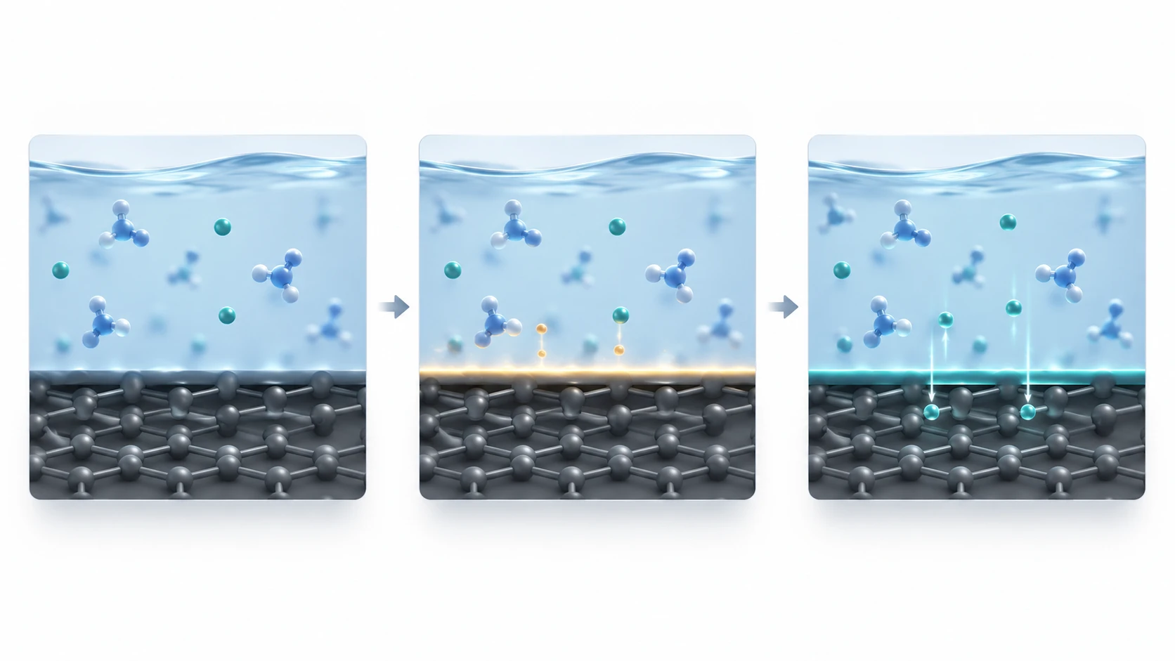
- Before the first charge: electrolyte directly contacts the graphite anode
- During the first charge: some electrolyte decomposes and forms a thin SEI
- Later cycles: the SEI blocks electrons, passes ions and suppresses further decomposition
3. A materials engineer's view (1): thermodynamically unstable, kinetically safe
The review puts the situation into a single image.
This is much like a region below sea level, as in the Netherlands, being protected from the sea by a dam: it is a fact that the protection the SEI provides is thermodynamically unstable.Sourced
And yet it is equally a fact that almost every graphite-based lithium-ion battery in the world relies on this mechanism to operate, which shows vividly how useful a kinetic barrier against a thermodynamic limit can be.Sourced
Thermodynamically unstable, but protected by a kinetic barrier — metallurgists have seen this picture many times.
Aluminium reacts readily with oxygen on thermodynamic grounds. It survives outdoors because the dense oxide film that forms on its surface stops any further oxidation. That is passivation.
The SEI is the same: not a reaction that was prevented, but a reaction allowed to happen once and then stopped by its own product.
Two practical consequences follow.
- Break the film and the reaction restarts. A passive layer that is scratched has to re-form. If the anode swells and shrinks on cycling, the film cracks
- The quality of the film is a matter of material choice. The review notes that trace hydrofluoric acid (HF) generated by hydrolysis of LiPF6 contributes to the formation of a good SEI at the anode interface, and that the FSI anion forms an SEI rich in lithium fluoride (LiF) on graphiteSourced
In liquid cells, in other words, the SEI is something you design. The solvent (EC), the salt (LiPF6, LiFSI) and the additives are chosen as materials for building a film. Of EC the review states that the leading actor in this scenario is the solvent ethylene carbonate (EC), which stabilises the anode through its part in SEI formation on carbon anodes and thereby makes the lithium-ion battery viable as a high-voltage secondary batterySourced.
At least part of electrolyte development is, in truth, film development (our commentary).
4. In a solid-state cell, the same thing becomes resistance
Now the solid-state case, where the story inverts.
When a sulfide solid electrolyte meets an electrode material and forms an interface, structural change and sulfur diffusion occur to a depth of about 10 nm from the LiCoO2 electrode surface. That is the chemical reaction layer, and when it is present at the interface it produces extremely high interfacial resistance.Sourced (Tokyo Institute of Technology, July 2022)
The same kind of naturally formed layer can play the opposite role
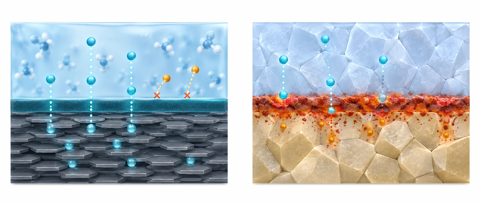
- An SEI forms between the liquid electrolyte and anode
- It blocks electrons while allowing Li⁺ to pass
- It suppresses further electrolyte decomposition
- A chemical reaction layer forms between a sulfide electrolyte and LiCoO2 cathode
- It involves structural change at the electrode surface and sulfur diffusion
- It leads to extremely high interfacial resistance
| Item | SEI in a liquid cell | Chemical reaction layer in a solid-state cell |
|---|---|---|
| What forms it | Reductive decomposition products of the electrolyte | Reaction between solid electrolyte and electrode material (structural change, sulfur diffusion) |
| Where it forms | The anode surface | The electrode / solid electrolyte interface (observed on the cathode side too) |
| Its role | Prevents any further decomposition of the electrolyte | Produces extremely high interfacial resistance |
| Electrical character | Electronically insulating and ion-permeable | Not confirmed within the scope of this article |
| How design treats it | Something whose quality is tuned, with additives among other means | Something whose formation is suppressed by inserting a buffer layer |
The liquid column is Sourced (the review [Source 1]); the solid-state column is Sourced (Tokyo Institute of Technology [Source 2]). Arranging them as a contrast is this article's own presentation.
5. Our calculation: ten times the thickness, ten times the resistance
What decides whether a layer at the interface is a protective film or an obstructive wall comes down to how much resistance it adds. Area-specific resistance is thickness divided by conductivity.
- Assumption: take the ionic conductivity of the layer as 10⁻⁶ S/cm (our own assumption, not a published value)
- At 10 nm thickness (= 1×10⁻⁶ cm): 1×10⁻⁶ divided by 10⁻⁶ = 1 Ω cm²
- At 100 nm thickness: 1×10⁻⁵ divided by 10⁻⁶ = 10 Ω cm²
What matters is not the absolute value but the proportionality. Whatever conductivity you assume, ten times the thickness gives ten times the area-specific resistanceOur calculation.
As the Interfacial resistance article in this series sets out, reported interfacial resistances span 1.5 to 225 Ω cm²Sourced. A layer that is harmless while thin starts to dominate once it thickens — that is the essence of interface design.
Assumptions and limits: the actual ionic conductivity of an SEI or a chemical reaction layer could not be found in published primary sources within the scope of this article. The absolute values above (1 and 10 Ω cm²) are therefore illustrations resting on an assumption, not real values. All this calculation is meant to show is the proportionality to thickness.
6. Which is why you prevent the layer instead of growing it
The countermeasures point in clearly opposite directions in liquid and solid-state cells.
In liquid cells, electrolyte additives have functioned as the materials that set the quality of the SEISourced. Small quantities, large effect, high value added — a textbook functional-materials business.
In solid-state cells that role migrates to buffer layers and coating materials. As the Interfacial resistance article in this series shows, coating cathode active material particles with LiNbO3 at a thickness of 6 to 20 nm is approaching practical useSourced.
From an additive dissolved in a liquid to a film deposited on a powder. The quantities, the equipment and the evaluation methods all change.
What does not change is that both are present in tiny amounts and govern the few nanometres at the interface. The material that makes the interface decides the performance of the cell — that shape is unaltered (our commentary).
7. A materials engineer's view (2): the SEI turned into a mechanics problem

In March 2026, Rice University and the University of Houston reported a new aspect of the SEI in a paper published in ScienceSourced.
Plated lithium shows unexpectedly high strength and brittle behavior under mechanical stress. The cause is the SEI shell covering the surface, which enhances their structural rigidity and prevents the dendrites' lithium core from deforming plasticallySourced. The University of Houston release puts it as having proven they are actually brittle and snap like glassSourced.
The SEI has long been discussed in the language of electrochemistry: does it pass electrons, does it pass ions, how many moles of lithium does it consume.
The 2026 work brings in the language of mechanics: rigidity, plastic deformation, brittle fracture.
To anyone who works with composites this is a familiar picture. A soft core wrapped in a thin hard shell — apparent strength goes up and ductility goes away.
And as the Lithium metal anode article in this series sets out, the design of lithium metal anodes rested on the premise that lithium is soft, so pressure will make it conform. The SEI undermines that premise.
What follows is that the composition and thickness of the SEI are part of the mechanical design of the anode. Choosing an electrolyte additive may be choosing whether the lithium that plates out bends or snaps — electrochemistry and mechanics meeting on the same few nanometres (our commentary).
8. What interfacial layers do in solid-state cells, and what is still hard
In May 2025, AIST and Toray Research Center published results from a multi-technique instrumental study of what causes all-solid-state cells to lose performanceSourced.
The work established that delamination at the interface between active material and solid electrolyte inside an all-solid-state cell under charge-discharge cycling, together with chemical structural change in the solid electrolyte, lowers ionic conductivitySourced. Specifically, in a cycled all-solid-state cell the electrode active material and the solid electrolyte have separated inside the cathode, and the chemical structure of the sulfide solid electrolyte has changedSourced (AIST, 12 May 2025; published in ACS Applied Energy Materials)
(1) Few numbers exist for the conductivity or thickness of SEI and reaction layers
The only figures this article could confirm are that the chemical reaction layer extends to a depth of about 10 nm and that the buffer layer is about 10 nm thickSourced. Their ionic conductivities, and the thickness and conductivity of the SEI in liquid cells, could not be found in published primary sources within the scope of this article and are therefore not stated.
(2) Whether to call the solid-state interfacial layer an SEI is unsettled
This article follows the Tokyo Institute of Technology and calls it a chemical reaction layer. Whether the layer forming at a solid-state interface should be given the same name, SEI, as in liquid cells is not treated consistently in the material consulted within the scope of this article. The mapping of terms is this article's own.
(3) Layers of atmospheric origin add to the problem
Not every layer at the interface comes from reactions inside the cell. For bonding lithium metal to LLZO, Tohoku University describes it as a major obstacle to practical use that an insulating lithium carbonate layer (Li2CO3) forming on the surface produces high interfacial resistanceSourced. Mere exposure to air during manufacture is enough to put a layer at the interface.
- The SEI in a liquid cell is an electronically insulating, ion-permeable interface film formed from the reductive decomposition products of the electrolyte during the first chargeSourced
- The electrolyte has no inherent tolerance to reduction at the anode. The SEI gives it an apparent durabilitySourced
- This is the same kinetic barrier as passivation in corrosion protection (our commentary)
- In a solid-state cell, a layer that forms just as spontaneously produces extremely high interfacial resistanceSourced
- Area-specific resistance is proportional to thickness. Harmless while thin, decisive once thickOur calculation
- So liquid cells grow the film and solid-state cells prevent the layer. A 10 nm buffer layer cut internal resistance to 1/2,800Sourced
- In 2026 the SEI became a mechanics problem too. The shell stops the core from deforming plasticallySourced
9. Glossary
- SEI
- Solid electrolyte interphase. The electronically insulating, ion-permeable film that forms on the anode surface during the first charge.
- Chemical reaction layer
- The altered layer produced where a solid electrolyte meets an electrode material. The source of interfacial resistance in solid-state cells.
- Buffer layer
- A thin artificial layer placed at the interface to suppress formation of the reaction layer. About 10 nm is enough to work.
- Passivation
- A state in which a surface film has stopped any further reaction. A standard idea in corrosion protection.
- Kinetic barrier
- A state in which a reaction that should proceed thermodynamically is so slow that it is effectively stopped.
- EC (ethylene carbonate)
- A principal solvent in lithium-ion batteries, involved in SEI formation on carbon anodes.
- LiPF6
- The most widely used lithium salt. Trace HF from its hydrolysis is said to contribute to SEI formation.
- LiFSI
- An imide-type lithium salt, said to form a LiF-rich SEI on graphite.
- Reductive decomposition
- Decomposition on accepting electrons. This is what the electrolyte undergoes at the anode.
- Area-specific resistance (Ω cm²)
- Resistance per unit area. Thickness divided by conductivity gives it.
- Lithium carbonate (Li2CO3)
- An insulating surface layer formed by reaction with components of the air. A source of interfacial resistance.
- Plastic deformation
- Deformation that remains after the load is removed. Without it, a material breaks brittlely.
10. Primary sources
- Masashi Ishikawa (Faculty of Chemistry, Materials and Bioengineering, Kansai University) "Development trends in electrolytes for lithium secondary batteries", GS Yuasa Technical Report vol. 15 no. 2 (December 2018), review article (PDF, Japanese-language page) — gs-yuasa.com
- Tokyo Institute of Technology "Origin of interfacial resistance in all-solid-state lithium batteries identified, with interfacial resistance cut to 1/2,800", July 2022 (Japanese-language page) — titech.ac.jp
- AIST "Causes of performance loss in all-solid-state batteries elucidated by multi-technique instrumental analysis", 12 May 2025, joint release with Toray Research Center (Japanese-language release) — aist.go.jp
- Rice University "Thorny issue plaguing lithium-ion batteries laid bare in new study", 12 March 2026 — news.rice.edu
- University of Houston "UH Research Reveals Lithium Dendrites Cause Battery Safety Risks", 8 April 2026 — uh.edu
- Tohoku University "Interface between lithium metal and a garnet-type oxide solid electrolyte formed at room temperature in a short time", 24 March 2026 (Japanese-language release) — tohoku.ac.jp
- JFE Techno-Research "Evaluation technology established for the coverage uniformity of coating layers on electrode active material surfaces, which govern all-solid-state battery performance", 10 September 2025 (Japanese-language release) — jfe-tec.co.jp
11. Claim-to-source audit
| Claim in the text | Basis | Label |
|---|---|---|
| That one would like the electrolyte not to decompose or degrade at the operating potentials of the electrodes, which holds for the cathode but not for the anode; that the SEI is an electronically insulating, ion-permeable electrode interface film formed from the reductive decomposition products of the electrolyte during the first charge, and that it prevents further decomposition; that the electrolyte, having no inherent tolerance to reduction, acquires an apparent durability because it is electronically insulated by those first decomposition products; the comparison with a region below sea level protected by a dam and the statement that the protection is thermodynamically unstable; that almost every graphite-based lithium-ion battery in the world relies on this mechanism, showing the usefulness of a kinetic barrier against a thermodynamic limit; that EC is the leading actor and stabilises the anode through SEI formation; that trace HF from hydrolysis of LiPF6 contributes to a good SEI; and that the FSI anion forms a LiF-rich SEI on graphite | Review, GS Yuasa Technical Report vol. 15 no. 2[Source 1] https://www.gs-yuasa.com/en/technology/technical_report/pdf/vol15_2/015_02_001.pdf | Sourced |
| That when a sulfide solid electrolyte meets an electrode material, structural change and sulfur diffusion occur to about 10 nm depth from the LiCoO2 surface, that this is the chemical reaction layer, and that its presence produces extremely high interfacial resistance; and that introducing a Li3PO4 solid electrolyte of about 10 nm as a buffer layer at the Li3PS4 and LiCoO2 interface cut the internal resistance of the cell to 1/2,800 of its previous value | Tokyo Institute of Technology news, July 2022[Source 2] https://www.titech.ac.jp/news/2022/064488 | Sourced |
| That delamination between active material and solid electrolyte under cycling, together with chemical structural change in the solid electrolyte, lowers ionic conductivity; that in a cycled cell the active material and solid electrolyte have separated inside the cathode and the chemical structure of the sulfide solid electrolyte has changed; and that the announcement dates from 12 May 2025, by a research team from Toray Research Center and AIST, published in ACS Applied Energy Materials on 4 April 2025 | AIST press release, 12 May 2025[Source 3] https://www.aist.go.jp/aist_j/press_release/pr2025/pr20250512_2/pr20250512_2.html | Sourced |
| That plated lithium shows unexpectedly high strength and brittle behavior under mechanical stress; that the SEI coating enhances their structural rigidity and prevents the dendrites' lithium core from deforming plastically; and that the paper appeared in Science on 12 March 2026 | Rice University news, 12 March 2026[Source 4] https://news.rice.edu/news/2026/thorny-issue-plaguing-lithium-ion-batteries-laid-bare-new-study | Sourced |
| The wording that the work has proven they are actually brittle and snap like glass | University of Houston news, 8 April 2026[Source 5] https://www.uh.edu/news-events/stories/2026/april/04082026-lithium-battery-weakness.php | Sourced |
| That in bonding lithium metal to LLZO, an insulating lithium carbonate layer (Li2CO3) forming on the surface produces high interfacial resistance and has been a major obstacle to practical use; and that the interfacial resistance was about 225 Ω cm², falling to about 1.5 Ω cm² when an Au layer was used | Tohoku University press release, 24 March 2026[Source 6] https://www.tohoku.ac.jp/japanese/2026/03/press20260324-02-Lithium.html | Sourced |
| That an evaluation technology for LiNbO3 coating on cathode active material particles was established over a target thickness range of 6 to 20 nm | JFE Techno-Research news release, 10 September 2025[Source 7] https://www.jfe-tec.co.jp/information/release/r20250910.html | Sourced |
| Putting the area-specific resistance of a 10 nm layer at 1 Ω cm² and of a 100 nm layer at 10 Ω cm², and the statement that ten times the thickness gives ten times the area-specific resistance | Our calculation. Taking the ionic conductivity of the layer as 10⁻⁶ S/cm is our own assumption and is neither a published nor a measured value. The absolute figures are illustrations resting on that assumption, and all the calculation shows is the proportionality in area resistance = thickness divided by conductivity | Our calculation |
| Numerical values for the ionic conductivity of the SEI and of the chemical reaction layer, and for the thickness of the SEI in liquid cells | Not found in published primary sources within the scope of this article, so not stated. The only figures confirmed are that the chemical reaction layer extends to about 10 nm depth and that the buffer layer is about 10 nm thick | Commentary |
| Whether the layer forming at a solid-state interface should be called an SEI, as in liquid cells | No consistent treatment could be confirmed in the material consulted within the scope of this article, so the text follows the Tokyo Institute of Technology and calls it a chemical reaction layer. The mapping of terms is this article's own | Commentary |
| Whether the chemical reaction layer in a solid-state cell is electronically insulating or ion-permeable | Could not be confirmed in the material this article consulted, so the comparison table records it as not confirmed | Commentary |
| Framing the SEI as the same idea as passivation in corrosion protection; the reading that a cracked film restarts the reaction; the framing that part of electrolyte development is film development; the contrast between growing a film and preventing a layer; the reading that the additive business migrates to buffer layers and coating materials; the reading that SEI composition and thickness constitute mechanical design of the anode; and the grouping of solid-state interfacial effects into three | Our summary and commentary based on published content. Not a view expressed by any of the institutions | Commentary |
| That Figs. 1, 2, 3, 4 and 6 are explanatory concepts rather than real observations or measured data; that the hero image and Figs. 1, 2 and 5 are AI-generated; and that the hero and Fig. 5 are metaphors while Figs. 1 and 2 schematize scientific relationships | Our note | Commentary |
Last updated 21 September 2026. Sources are limited to primary material (a review published in a peer-reviewed technical report, and official announcements from universities, national research institutes and companies). Because the article includes structural readings and materials-design interpretations, those are marked as Commentary and kept separate from sourced fact. The ionic conductivity of the SEI and of the chemical reaction layer, and the thickness of the SEI in liquid cells, are not stated here because no published primary source could be confirmed. The absolute values in Section 5 (1 and 10 Ω cm²) are illustrations resting on an assumption, not measurements. What they show is only the proportionality to thickness. All figures are explanatory concept graphics. Figs. 3, 4 and 6 are vector drawings; the hero image and Figs. 1, 2 and 5 are AI-generated images, and none of them shows a real cross-section, micrograph or the SEI itself.