TECHNOLOGY EXPLAINER
Polymer Blends and Fillers
— the design of the interface begins the moment you mix
Polymers are rarely used on their own. They are mixed with other polymers (blends), packed with particles or fibres (fillers), dosed with small amounts of chemicals (additives), and, in battery electrodes, made to act as the glue that holds particles together (binders). The difficulty they share is how to handle the boundary between different phases: the interface. This article sorts out why polymers resist mixing, compatibilisation, fillers and their interfaces, binders, and additives and bleed, from a materials engineer's point of view.
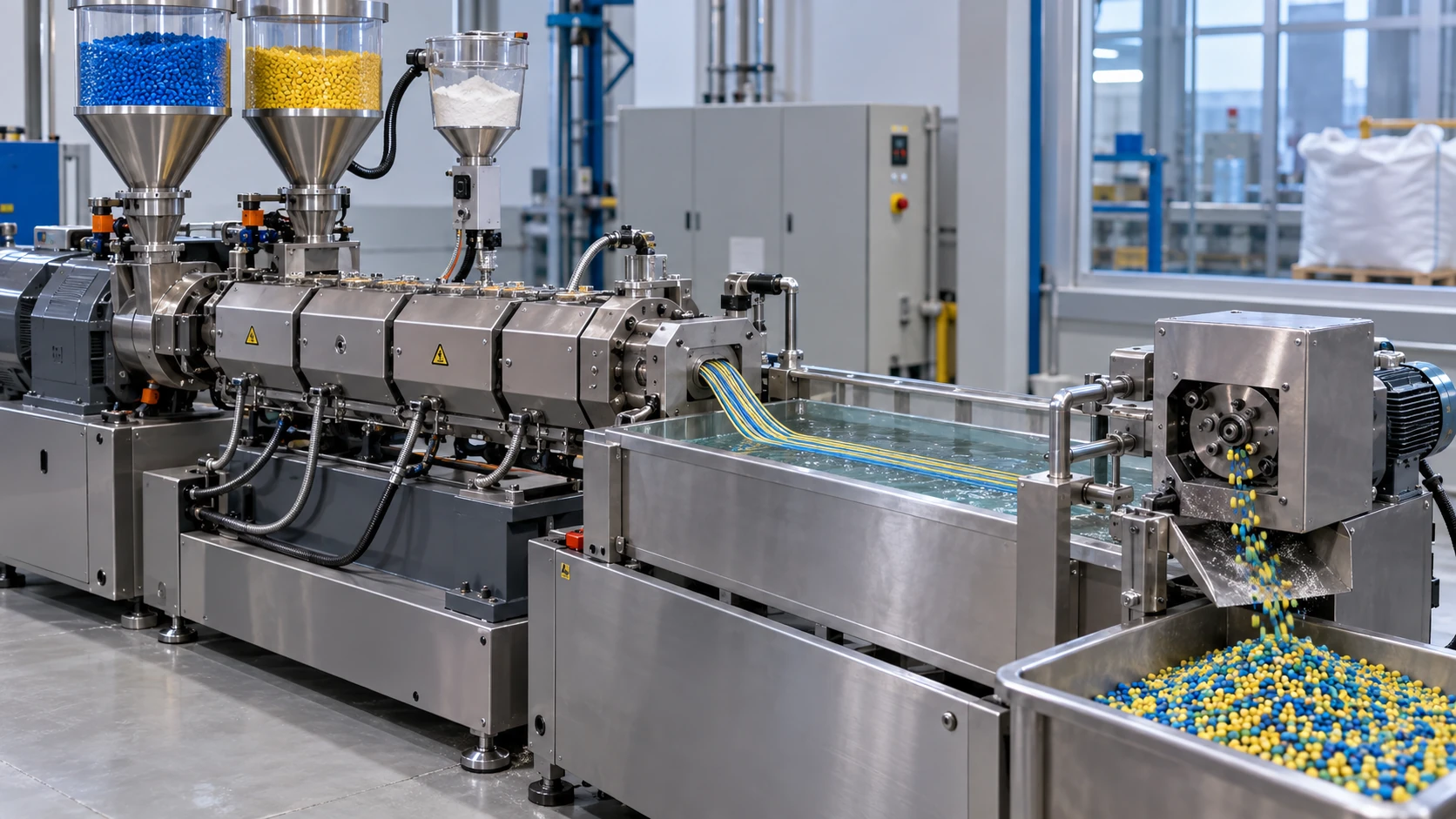
- Blends, fillers, additives and binders (the short version)
- Polymer blends — not mixing is the norm
- Our calculation: why a high degree of polymerisation prevents mixing
- Forms of phase separation, and compatibilisers
- A materials engineer's view (1): blending is less about mixing than about designing the interface
- Fillers — what goes in, and what changes
- Our calculation: mass % and volume %, particle size and interfacial area
- The interface between filler and polymer
- A materials engineer's view (2): an interface can be a defect or a function
- Binders — the glue of a battery electrode
- Additives — antioxidants, flame retardants, plasticisers
- Bleed — where does additive that cannot dissolve go?
- A materials engineer's view (3): additives are a solubility problem
- What is still hard, and what we could not confirm
- Glossary / References / Claim-to-source audit
Sourced = content stated in published material from a standards body, paper, company or public agency (link given)
Our calculation = a figure this article derived, with the assumptions spelled out
Not yet confirmed = a plan, target or outlook with no confirmed track record
Structural readings and materials-design interpretations are marked separately as Commentary.
Property values are always shown together with the test method, conditions and source. Densities and similar inputs used in our calculations are assumptions set by this article, not values for any specific product.
1. Blends, fillers, additives and binders (the short version)
- Polymer blends: using two or more polymers mixed together. Polymers of high degree of polymerisation, however, normally resist mixing, and the structure left after mixing (the form of the phase separation) decides the propertiesSourced
- Fillers: packing in particles or fibres of glass, talc, silica, carbon and so on to change stiffness, heat resistance, dimensional stability, electrical conductivity and more. The effect is set not just by the amount but by the size of the particles and their interface with the polymer (our commentary)
- Additives and binders: chemicals that work in small amounts (antioxidants, flame retardants, plasticisers), and the glue that ties particles together (the binder in a battery electrode). Precisely because the amounts are small, they come with the problem of not fully dissolving and coming out onto the surface (bleed) (Section 12)
Compounding polymers is less a question of "what to mix" than of "how to build the boundary". The review by Fredrickson et al. (ACS Polymers Au, 2022) says that, because the entropy of mixing for polymers is small, blends of dissimilar polymers are usually immiscible and have poor properties, and that truly miscible polymer alloys are few, with polystyrene / poly(p-phenylene oxide) cited as a commercially used exampleSourced. If not mixing is the rule, every practical material is designed to be used without having mixed (our commentary).
Blends of polycarbonate and ABS resin are covered in our explainer on polycarbonate and ABS resin. Composites that use glass or carbon fibre in continuous lengths are in our explainer on CFRP and composite materials, and fillers used to match thermal expansion were covered in our explainers on the coefficient of thermal expansion, underfill and molding. This article sticks to the common groundwork beneath those.
2. Polymer blends — not mixing is the norm
The review by Fredrickson et al. sets out the followingSourced.
- Chemically different polymers are rarely miscible over the whole composition range, because the entropy of mixing per unit volume falls in proportion to 1/N, the inverse of the degree of polymerisation N
- Alloys that are miscible at high molecular weight need either pairs of very similar structure, such as isotopes or isomers, or a specific attraction such as hydrogen bonding
- A typical immiscible blend separates macroscopically; its interface is narrow and there is little chain entanglement between the phases, so its mechanical properties are poor
- The properties of an immiscible blend can change with the time and history of melt or solution processing (because the morphology evolves with time)
For materials engineers, the closest picture is a binary system in a metal phase diagram that does not form a solid solution. In polymers, the entropy that drives mixing shrinks as chains get longer, so they resist mixing even more than metals do (our commentary).
3. Our calculation: why a high degree of polymerisation prevents mixing
In the lattice model set out by Flory (1942) and Huggins (1941), the free energy of mixing is written as an entropy-of-mixing term (the volume fraction φ of each component divided by its degree of polymerisation N) plus a term in the interaction parameter χSourced (the titles of the original papers are in [References 2 and 3]).
Assumptions (the simplest case)Our calculation
- Both components have the same degree of polymerisation N (a symmetric blend). There is no volume change on mixing, and χ depends neither on composition nor on N
- The critical point for phase separation is then χc = ½(1/√N1 + 1/√N2)2, which for N1 = N2 = N gives χc = 2 / N
| Degree of polymerisation N | χc = 2 / N | How to read it |
|---|---|---|
| 1 (small molecule) | 2 | Mixes even with some repulsion (a χ above 2 is a fairly strong repulsion) |
| 10 (oligomer) | 0.2 | Mixes readily |
| 100 | 0.02 | Starts to separate with a small repulsion |
| 1,000 | 0.002 | Separates with even a very small repulsion |
| 10,000 | 0.0002 | Close to practical high molecular weights. Essentially "does not mix" |
Raise the degree of polymerisation tenfold and the repulsion that can be tolerated while still mixing (χc) falls to one tenth. The degree of polymerisation of real commodity polymers often runs to thousands or tens of thousands, so a χ that is only slightly positive is enough to stop mixing. That is the quantitative meaning of "not mixing is the norm".
Assumptions and limits: real polymer combinations have different degrees of polymerisation, and χ also depends on temperature and composition. With a specific attraction such as hydrogen bonding, χ can become negative and the polymers can be miscible (Fredrickson et al.). This calculation is meant to give a feel for orders of magnitude and does not predict the miscibility of any particular pair.
4. Forms of phase separation, and compatibilisers
In a blend that does not mix, the properties depend on the form in which the two phases separate (our commentary). There is the "sea-island" structure, in which one phase is scattered as islands in the other, and the "co-continuous" structure, in which both are continuous and interlaced. The size and distribution of the islands depend on the mixing conditions and on the nature of the boundary (interface) between the two phases.
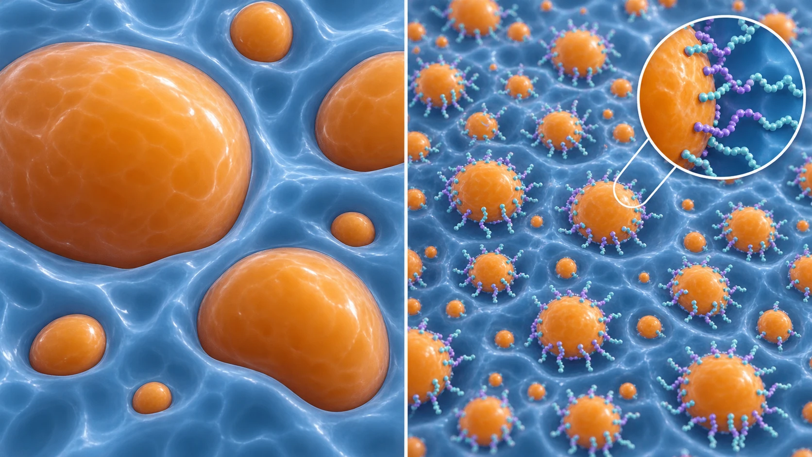
ImageGen conceptual illustration (not a real photograph or measurement). See the original diagram for exact values, names and structure.
Show original diagram with exact annotations and values
Fredrickson et al. summarise the methods of compatibilisation as followsSourced.
- Add a block or graft copolymer to lower the interfacial tension, make the interface broader and stronger, and keep the multiphase morphology from coarsening
- A reactive blend that makes the copolymer in situ by reaction between functional groups on the two polymers. Mixing and reaction usually happen together in the melt inside an extruder
- The links in the copolymer are mostly covalent or hydrogen bonds, but the authors argue that methods using ionic bonds or electrostatic interactions still have room to be exploited
The review by Koning et al. (Progress in Polymer Science, 1998) is known as a classic survey of compatibilisation strategiesSourced (we confirmed only the title and journal [Reference 8]; we have not checked the details of the text).
Telling phase separation from mixing — using the glass transition
Whether two polymers have mixed at the molecular level can be judged from clues in the glass transition temperature (Tg) (our commentary). Measured by differential scanning calorimetry (DSC), a miscible blend generally shows a single Tg, somewhere between those of the components. A phase-separated blend normally keeps a separate Tg for each component. ISO 11357-2:2020 defines how to determine glass transition temperature and step height by DSC for amorphous and semi-crystalline plasticsSourced (we confirmed only the number, title and scope statement [Reference 5]). The meaning of Tg itself is covered in our explainer on glass transition and creep.
5. A materials engineer's view (1): blending is less about mixing than about designing the interface
Two immiscible phases, one dispersed as fine islands and firmly joined at the boundary: this is the same design philosophy as two-phase microstructures and dispersion strengthening in metals (our commentary). The difference is that in polymers it is chain entanglement that builds the interface. Fredrickson et al. put the poor mechanical properties of immiscible blends down to a narrow interface with little chain entanglement between the phases, and this is the important pointSourced.
- The compatibiliser's job is not "to mix" but "to thicken the interface": the copolymer lines the interface and pushes chains into the phase on each side. It is close in spirit to the interface of a diffusion bond in metals, giving the interface "thickness"
- The morphology changes with time: the structure of an immiscible blend can change with processing history (Fredrickson et al.). Islands coalescing and coarsening in the melt can be read as a phenomenon like Ostwald ripening in metals (commentary)
- A measurement pitfall: even if DSC shows a single Tg, it may be impossible to tell the cases apart when the phase size is small (commentary; we have not checked numbers for the resolution). Judge by combining it with observation, for example by electron microscopy
How good a blend is depends not only on the recipe (blend ratio) but on the mixing conditions (temperature, shear, time) and the type and amount of compatibiliser. In metal terms, it is like the way structure is set by heat treatment as well as by composition.
6. Fillers — what goes in, and what changes
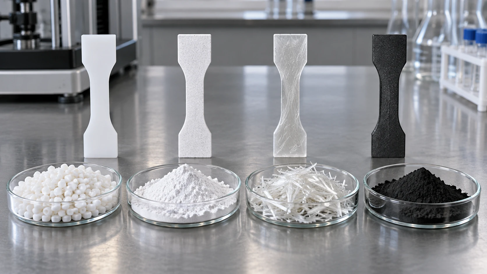
Fillers are particles or fibres mixed into a polymer. The table sorts the main ones by aim and by caution (the table is our commentary; the individual sources are given below it).
| Filler | Main aim | Caution |
|---|---|---|
| Glass fibre | Raise stiffness, strength and heat resistance (such as deflection temperature under load) | Properties change with fibre orientation (anisotropy). Also affects warpage and appearance |
| Talc and mica (platy minerals) | Raise stiffness and dimensional stability and curb moulding shrinkage | Being platy, they line up in one direction. Impact strength can fall |
| Silica | Reinforce rubber; lower thermal expansion (such as semiconductor encapsulants) | Hydrogen bonding between surface silanol groups makes it agglomerate. Surface treatment (coupling agent) is needed |
| Carbon (carbon black, graphite, carbon nanomaterials) | Reinforcement, electrical conductivity, colouring. Conductive additive in battery electrodes | Too little and the conductive paths do not connect; too much and processability falls |
| Nanofillers (nanoclay, nanosilica and so on) | Increase interfacial area with a small amount, aiming at barrier, flame retardancy, strength and so on | Prone to agglomerate and hard to disperse. Whether a "nano effect" is real depends on the system |
The table is our commentary. It rests on: ISO 1172 for how glass fibre content is determined [Reference 4]; the review by Bokobza for the reinforcement of rubber by carbon black and silica and for silica agglomeration [Reference 6]; and the review by Paul and Robeson for the aims of nanocomposites (barrier, flame retardancy, electrical properties) and the question of the "nano effect" [Reference 7]. We do not cover specific values (strength, modulus and so on).
ISO 1172:2023 defines a method of determining the content of glass fibre and mineral filler in glass-fibre-reinforced plastics by calcination (burning off the resin). Its scope includes prepregs, SMC, BMC and DMC, and thermoplastic moulding materials and pellets reinforced with glass fibreSourced. In other words, filler amount is stated by mass as "so many % glass", and there is a standard method that weighs what remains as ash after burning.
The review by Paul and Robeson (Polymer, 2008) organises polymer-based nanocomposites across exfoliated clay nanocomposites, barrier properties, flame retardancy, biomedical uses, electrical, electronic and optical uses, and fuel cells, and takes up the important question of how the "nano effect" of adding nanoparticles or fibres shows in crystallisation and glass-transition behaviour compared with larger-scale fillersSourced.
7. Our calculation: mass % and volume %, particle size and interfacial area
Assumptions (set by this article)Our calculation
- Assume the density of glass fibre is 2.5 g/cm³ and that of the matrix resin 1.1 g/cm³ (not values for any specific grade)
- Assume no voids, with volume % = the glass share of the sum of mass divided by density
| Glass, mass % | Volume % |
|---|---|
| 10 | about 4.7 |
| 20 | about 9.9 |
| 30 | about 15.9 |
| 40 | about 22.7 |
The formula is volume % = (w / 2.5) / {(w / 2.5) + ((1 − w) / 1.1)}, where w is the mass fraction. For example, at w = 0.30, 0.12 / (0.12 + 0.636) = 0.159. Glass at 30% by mass is a little under 16% by volume. The denser the filler, the wider the gap between mass % and volume %.
Assumptions and limits: the densities of glass and resin are assumed values; real values differ with glass composition, resin type and temperature. Properties (modulus, thermal expansion and so on) often depend on volume fraction, so when comparing materials you need to align either mass % or volume % (our commentary).
AssumptionsOur calculation
- Assume the filler is spheres of diameter d dispersed at 1 vol% (φ = 0.01)
- The surface area per volume of a sphere is 6 / d. The interfacial area per 1 cm³ of composite is then φ × 6 / d
| Particle size d | Interfacial area (per 1 cm³ of composite) | Ratio, with 10 µm as 1 |
|---|---|---|
| 10 µm | 60 cm² | 1 |
| 1 µm | 600 cm² | 10 |
| 100 nm | 6,000 cm² (0.6 m²) | 100 |
| 20 nm | 30,000 cm² (3 m²) | 500 |
When the particle size falls to a tenth, the interfacial area at the same volume % becomes ten times larger. Going from 10 µm to 20 nm gives 500 times (10 µm / 20 nm = 500). Bokobza says that nanoscale fillers have a far larger polymer-filler interface than micron-scale ones, and so are expected to give a much greater reinforcing effectSourced.
Assumptions and limits: real particles agglomerate into lumps, are not spheres, and have a size distribution. Agglomeration reduces the effective interfacial area. This calculation is meant to convey in orders of magnitude what making particles smaller means.
8. The interface between filler and polymer
Bokobza's review (Polymers, 2023) sets out the role of the interface, taking rubber reinforcement as the exampleSourced.
- Adding active fillers such as carbon black or silica normally improves modulus and fracture properties
- Filled rubbers show two characteristic behaviours involving energy dissipation: the Payne effect (a non-linear viscoelastic response in which the storage modulus G′ falls as strain amplitude rises) and the Mullins effect (stress falls on a second stretch). Both depend strongly on interfacial adhesion and filler dispersion
- The Payne effect is explained mainly by the breakdown of the filler's agglomerate structure, and is tied to the state of filler dispersion and the strength of polymer-filler interaction
- In fumed silica, hydrogen bonding through surface silanol groups readily causes agglomeration. A surface treatment that deactivates part of the silanol groups reduces filler-filler interaction and lowers the size of the Payne effect
- When compatibility is poor, as between a hydrocarbon rubber and silica, a coupling agent such as bis(3-triethoxysilylpropyl) tetrasulfide (TESPT, commonly Si69) helps dispersion and improves adhesion between the organic and inorganic phases. The ethoxy groups react with the silica and the tetrasulfide part with the rubber
- In an example with silica in SBR, without a coupling agent the filler network dominates at low strain, and the initial modulus and the amplitude of the Payne effect are larger
9. A materials engineer's view (2): an interface can be a defect or a function
As Bokobza's review shows, filler agglomeration raises stiffness at low strain (the Payne effect), while interfacial adhesion bears on strength and fatigue. The same "interface" is judged in opposite ways by different applications (our commentary).
- As a defect: interfacial debonding and agglomerates become starting points of fracture, just as inclusions and interface debonding do in metal composites
- As a function: the agglomerate structure of a conductive filler becomes a conductive path (percolation) once it connects. In encapsulants for semiconductor packages, thermal expansion is designed through the amount and dispersion of silica (our explainer on the coefficient of thermal expansion). In barrier materials, platy fillers are used to bend the gas path (our explainer on barrier properties and coatings; the barrier properties of nanocomposites also appear in the review by Paul and Robeson)
- Tools for control: surface treatment, coupling agents and sizing. For fibres, "sizing" plays the same role (our explainer on CFRP and composite materials)
For those who work with metals and ceramics, this is a field where experience of controlling the wetting and bonding between particle and matrix through surface treatment (as in ceramic-particle-dispersed metals) carries straight over. The difference is that in polymers the matrix is viscoelastic, and the motion of chains near the interface may change (the glass transition may shift at the interface). Bokobza describes an example in which, as filler content rises, regions of reduced mobility around the filler overlap and cause percolation, changing the stress-strain curve in a way that suggests a filler network formingSourced (an example of a network with in situ silica in which the shape of the curve changes beyond about 30 phr; phr is parts by mass per 100 parts by mass of resin).
10. Binders — the glue of a battery electrode
The electrode of a lithium-ion battery is made by coating a metal foil current collector with a mix of active material particles, a conductive additive and a binder. The binder is a polymer that links particles to each other and to the foil. What separates a filler from a binder is that the binder's job is "to join", and it is used in small amounts (our commentary).
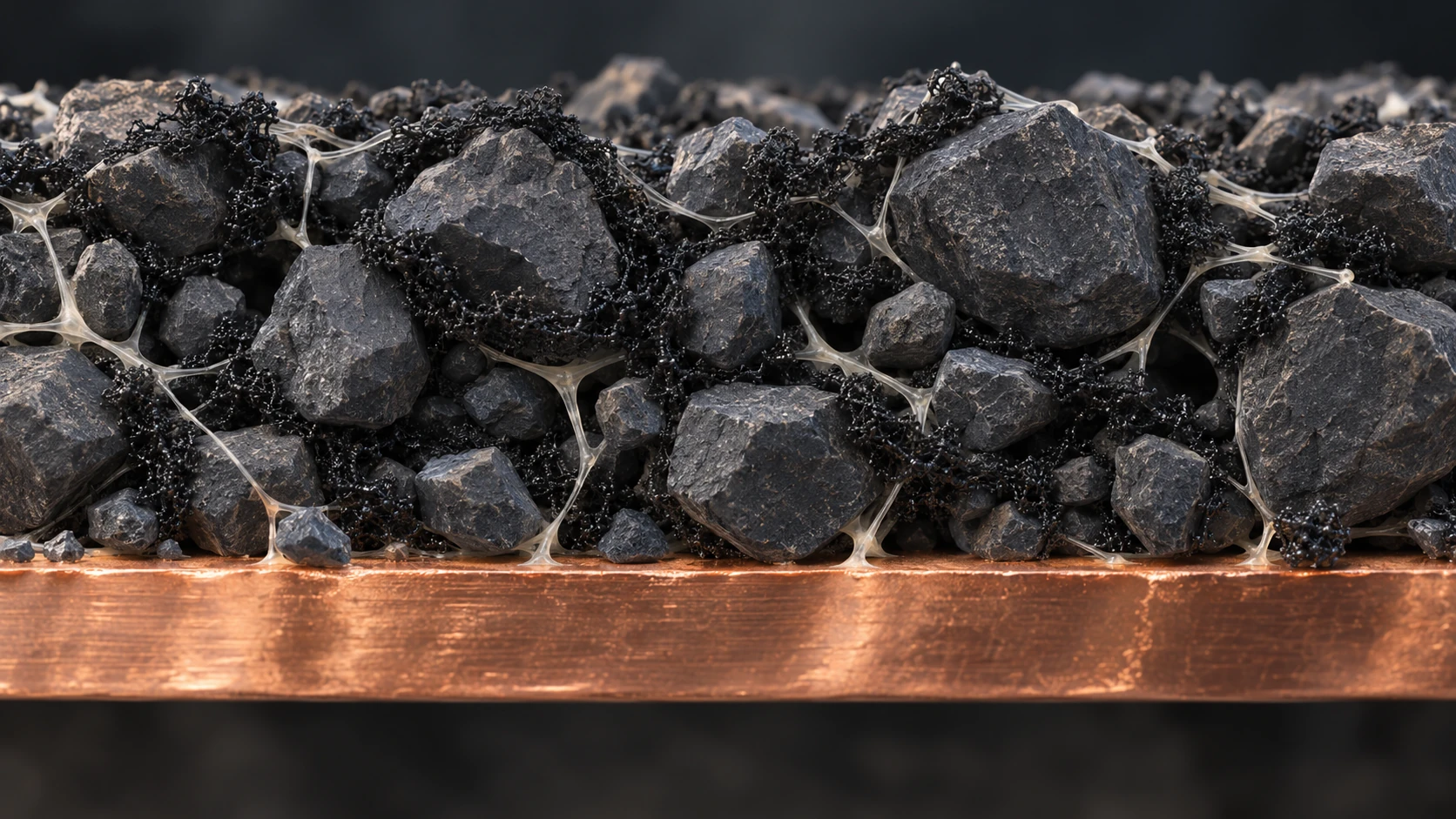
ImageGen conceptual illustration (not a real photograph or measurement). See the original diagram for exact values, names and structure.
Show original diagram with exact annotations and values
The review by Lee et al. (Polymers, 2023) states the followingSourced.
- The binder plays an important role in keeping the structural integrity of the electrode. Although it is a small fraction of the whole electrode, it has a large effect on battery performance
- The binder mostly takes no part in the battery's electrochemical reactions, so its mass ratio is small. Its main role is to hold the various components of the electrode together and keep the physical structure, which matters for the smooth movement of electrons and ions
- Polyvinylidene fluoride (PVDF) is favoured for its electrochemical stability and its ability to accommodate the mechanical compression and expansion during charge and discharge. On the other hand, conventional polymer binders such as PVDF have the drawbacks of low mechanical properties and thermal stability
- N-methyl-2-pyrrolidone (NMP) has been the standard solvent in making lithium battery electrodes, but because of toxicity concerns it faces growing environmental scrutiny and chemical regulation
- In studies of water-borne binders (SBR + CMC and others), there are examples in which PVDF risks letting the active material peel from the current collector and SBR + CMC is said to give better adhesion (a study on CuO electrodes is introduced)
Kureha, which makes PVDF binders, explains of its "KF Polymer" that even with less binder, it can keep the active material concentration high while preventing electrode delamination. Its grades range in molecular weight from 2.8×10⁵ to over 10×105 and in inherent viscosity from 1.1 to 3.1 dl/g, and the company says it was chosen as the binder in 1991, the year the lithium-ion battery was first commercialised in the worldSourced (the manufacturer's own description).
In Commission Regulation (EU) 2018/588 of 2018, the EU added a restriction on NMP (1-methyl-2-pyrrolidone) to Annex XVII of REACH (entry 71). It provides that substances and mixtures containing 0.3% or more of NMP may not be placed on the market after 9 May 2020 unless the manufacturer, importer or downstream user includes, in the chemical safety report and the safety data sheet, derived no-effect levels (DNEL) for worker exposure of 14.4 mg/m³ by inhalation and 4.8 mg/kg/day by the dermal routeSourced. It also provides that they may not be manufactured or used unless appropriate risk management measures are taken so that worker exposure stays at or below this DNELSourced. (This article confirmed only the text of the regulation, and has not checked how battery manufacturing sites are responding.)
Assumptions (set by this article)Our calculation
- Assume the active material particles are spheres 10 µm in diameter with a density of 4.0 g/cm³
- Assume the binder has a density of 1.8 g/cm³ and a mass ratio to active material of 2% (2 mass %)
- Assume the binder covers the particle surface uniformly (in reality it would not)
Binder layer thickness t = (binder volume / active material volume) × d / 6 = (0.02 / 1.8) / (1 / 4.0) × 10 µm / 6 = about 0.074 µm (74 nm).
For a particle 10 µm across, uniform coverage would give a film only about 74 nm thick. Real binder is thought to gather at contacts between particles and at contacts with the foil, or to sit unevenly in the gaps between particles (our commentary; we have not checked the real distribution). A binder that "joins with a small amount" is a design in which force is transmitted through points of contact.
Assumptions and limits: density and particle size are assumptions, not values for a real electrode. The distribution of the binder probably also depends on the drying conditions of the electrode, but we have not confirmed this.
11. Additives — antioxidants, flame retardants, plasticisers
(1) Antioxidants — the time they hold on grows with concentration
The review by Gijsman (e-Polymers, 2008) says that polymers degrade both during processing and in service, and that much of this is due to oxidative processesSourced. Antioxidants are what hold this in check. The study by Richaud et al. (Polymer Degradation and Stability, 2011) examined the induction period (the time before oxidation gets properly under way) of polypropylene stabilised with hindered phenols (2,6-di-tert-butylphenols), and showed that the length of the induction period is roughly proportional to the phenol concentration, and that the constant of proportionality hardly depends on the stabiliser's structure within the range of structures studiedSourced.
Read simply, this suggests that doubling the antioxidant concentration roughly doubles the induction period (our reading. It is "roughly proportional" over the range studied, not strictly proportional). In general, phosphites, which decompose hydroperoxides during processing, are used together with phenolic antioxidants (our commentary). The ability of organic phosphites to decompose hydroperoxides is also shown in the title of the study by Bauer et al. [Reference 14].
(2) Flame retardants — "how hard it is to burn" depends on the test
Flame retardancy means something different with each test method. Here we sort out two representative indicators.
- Oxygen index (OI): ISO 4589-2:2017 defines how to find, on a small vertical specimen, the minimum volume fraction of oxygen in a mixture with nitrogen that is needed to sustain combustion. The specimens are self-supporting bars or sheets up to 10.5 mm thick, and the scope is solid, laminated or cellular materials with an apparent density of 100 kg/m³ or moreSourced
- UL 94: a standard that evaluates the flammability of plastics used in parts of devices and appliances through small-scale tests against a small flame or a radiant heat source. It has grades HB (horizontal burning) and V (V-0, V-1, V-2; vertical burning)Sourced (from UL's explanatory material; a 3/4-inch, 50 W burner flame is applied to a specimen of about 5 × ½ inch). The same material states that many UL 94 test results cannot be applied to materials thicker than 13.0 mm or with a surface area over 1 m², and that building codes do not recognise small-scale UL 94 ratingsSourced
On regulation of flame retardants, the following is sourcedSourced. Annex II of the EU RoHS Directive (2011/65/EU) lists polybrominated biphenyls (PBB) and polybrominated diphenyl ethers (PBDE) with a maximum permitted concentration of 0.1% in homogeneous material. Hexabromocyclododecane (HBCD) was listed in Annex A of the Stockholm Convention in 2013 with specific exemptions for production and use in expanded polystyrene (EPS) and extruded polystyrene (XPS) in buildings. This article does not argue the merits of any particular flame retardant or company. For the substances covered and the exemptions, check the latest convention and legislation.
(3) Plasticisers — they soften, but they tend to leave
A plasticiser is an additive that dissolves into the polymer, makes the chains more mobile and so gives softness (our commentary. Its effect of lowering Tg is covered in our explainer on glass transition and creep). As regulation, the amendment to the RoHS Directive (Commission Delegated Directive (EU) 2015/863) restricted bis(2-ethylhexyl) phthalate (DEHP), butyl benzyl phthalate (BBP), dibutyl phthalate (DBP) and diisobutyl phthalate (DIBP) to 0.1% or less in homogeneous material in electrical and electronic equipment. It applies from 22 July 2019 (from 22 July 2021 for medical devices and monitoring and control instruments), and its recitals state that these four substances are substances of very high concern (SVHC)Sourced. Here too, we state only that the regulation exists, not an assessment of any individual product or company.
12. Bleed — where does additive that cannot dissolve go?
The review by Feschet-Chassot and Chennell (an arXiv preprint, 2025; it has not been peer reviewed) sorts out the loss of additives as followsSourced.
- Additives can be lost by evaporation (into the surrounding gas), extraction (into the surrounding liquid) and migration (into another polymer material in contact)
- When an additive is present above its saturation solubility, a supersaturated solution forms readily if the additive's melting point is lower than the polymer's, and the additive precipitates inside the polymer or on its surface. The latter process is called blooming (bleed)
- The loss is set by the speed of both mass transfer at the surface and diffusion from the interior to the surface
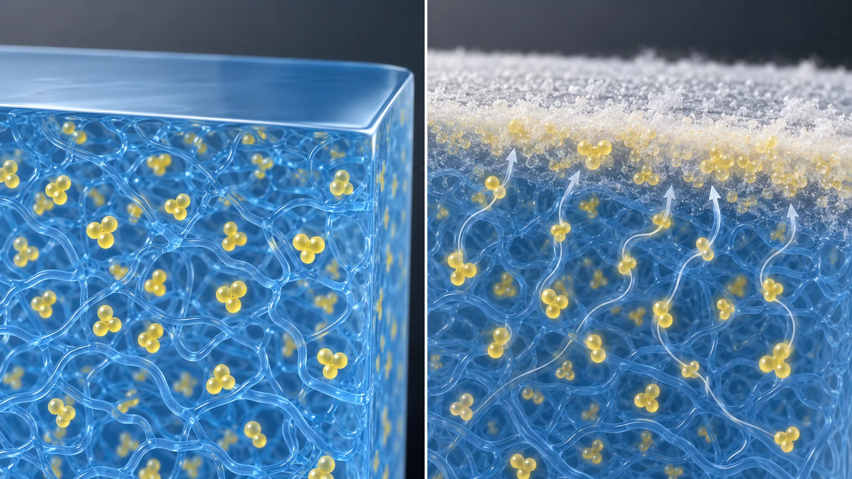
ImageGen conceptual illustration (not a real photograph or measurement). See the original diagram for exact values, names and structure.
Show original diagram with exact annotations and values
In applications that touch food, migration of additives is subject to regulation. EU Regulation (EU) No 10/2011 (plastic food contact materials) sets an overall migration limit of 10 mg per dm² of surface area and specific migration limits (SML) by substance, and provides that a general SML of 60 mg/kg applies to substances for which Annex I sets no limit or other provisionSourced (from the text of the 2011 regulation; we have not checked later amendments).
13. A materials engineer's view (3): additives are a solubility problem
An antioxidant holds on for a time proportional to its concentration (Richaud et al.). So you are tempted to add more. But there is an upper limit to its solubility in the polymer. Go beyond it and it bleeds (Feschet-Chassot and Chennell).
- The same pattern as the solid solubility limit in metals: an element beyond the solubility limit precipitates as another phase. An additive's "solubility in the polymer" is the polymer version of the solubility limit (commentary)
- It changes with temperature: for many substances, solubility changes with temperature. Additive dissolved during high-temperature processing may precipitate over time while the material is stored cooled to room temperature (commentary; we have not checked solubility values for individual additives)
- It is lost because it "dissolves and moves": if an additive is dissolved in a polymer, it can diffuse through the polymer. The transport thinking of P = D × S seen in our explainer on barrier properties and coatings applies equally to additive migration (commentary)
- Design options: ideas include raising molecular weight to slow diffusion, fixing the additive to the polymer by chemical bonding, or choosing a combination with higher solubility (commentary; we have not checked their adoption in individual products)
An additive's performance, and appearance defects from bleed or migration into another material in contact, are two sides of the same phenomenon. When selecting materials, the question is not only "how many years does it last at that amount?" but also "is that amount within the solubility range?" and "will it stay dissolved after cooling?"
14. What is still hard, and what we could not confirm
(1) We do not cover the interaction parameter χ of real polymer pairs
The calculation in Section 3 is an order-of-magnitude feel based on the simplest Flory-Huggins model. We have not checked the χ values of real polymer pairs or how they change with temperature and composition. We also do not cover the compositions of commercial blend materials or the specific chemical structures of compatibilisers.
(2) We give no numerical data on filler effects
The effects of glass fibre, talc, silica, carbon and so on on strength, modulus and thermal expansion vary greatly with grade, particle size, surface treatment and test method (ISO 527-1 and others), and we could not confirm primary sources that allow comparison under matched conditions. For that reason the calculations in Section 7 stop at conversions with assumed densities. We also give no values for percolation thresholds of conductive fillers.
(3) We do not cover quantitative binder performance
For battery electrode binders, numbers for adhesion strength, swelling and contribution to cell performance depend strongly on electrode formulation and measurement conditions and are not covered here. The calculation in Section 10 is an order-of-magnitude feel based on assumptions. We have also not checked how battery manufacturing sites are responding to the NMP regulation.
(4) We do not cover additive mechanisms, solubility or safety assessment
We have not confirmed, within the scope of this research, the details of how antioxidants, flame retardants and plasticisers act, the solubility of individual additives in polymers, or assessments of effects on people and the environment. Regulation is mentioned only to show that it exists; for items where established knowledge has to be distinguished from points still under discussion, refer to the latest assessments by the regulators. We have also not checked the text of standards that measure migration, such as ISO 177 (plasticiser migration tests).
(5) We have not used market size or share
We have not used market-size or share estimates from research firms. Statements about companies are limited to the companies' own product descriptions.
- Dissimilar polymers normally do not mix. The entropy of mixing falls as 1/N, and truly miscible systems are fewSourced. The critical value for a symmetric blend is χc = 2 / N (in this article's assumed model)Our calculation
- Practical blends are designed to be used without having mixed, with compatibilisers lowering interfacial tension and thickening the interface to stabilise the morphologySourced
- A filler's effect is set not only by amount but by particle size and interface. At the same 1 vol%, going from 10 µm to 20 nm particles multiplies interfacial area by 500Our calculation. Glass at 30 mass % is about 16 vol% at the assumed densitiesOur calculation
- For rubber reinforcement, silica agglomeration, the Payne effect and the improvement of the interface by coupling agents have been worked outSourced
- The binder in a battery electrode is a polymer that joins particles with a small amount. There are PVDF with NMP, and water-borne SBR + CMC; NMP is subject to a REACH restriction (entry 71) in the EUSourced
- Additives are a matter of solubility. The induction period of an antioxidant grows roughly in proportion to its concentration, but beyond its solubility it bleedsSourced
15. Glossary
- Polymer blend
- A material made by mixing two or more polymers. Most have a phase-separated structure.
- Miscibility
- Two polymers mixing at the molecular level. Immiscible means they do not mix and phase-separate.
- Compatibiliser
- A block or graft copolymer or similar that lines the interface, lowers interfacial tension and keeps the islands fine and stable.
- Reactive blending
- A method that makes the copolymer acting as compatibiliser in situ, by reaction during mixing.
- χ (interaction parameter)
- A number for the strength of interaction between two components. The larger and more positive it is, the harder they are to mix.
- Filler
- Particles or fibres added to a polymer, for aims as varied as reinforcement, dimensional stability and conductivity.
- Payne effect
- In filled rubber, the fall in storage modulus as strain amplitude rises. Related to the breakdown of the filler's agglomerate structure.
- Coupling agent
- A chemical that reacts with both the filler surface and the polymer to tie the interface together. A silane coupling agent is one example.
- Binder
- A polymer that ties together active material particles and foil, as in a battery electrode. Examples are PVDF and SBR + CMC.
- NMP
- N-methyl-2-pyrrolidone. Used in electrode manufacture as a solvent for PVDF. A restricted substance under REACH in the EU.
- Induction period
- The time before oxidation really starts to advance. The time during which an antioxidant is working.
- Oxygen index (OI)
- The minimum volume fraction of oxygen, in a mixture with nitrogen, at which burning continues.
- Bleed / blooming
- The precipitation of additive beyond its solubility onto the surface of the polymer.
- SML / OML
- The specific migration limit for each substance / the overall migration limit, for food contact materials.
16. References (primary sources)
- Fredrickson et al. Ionic Compatibilization of Polymers, ACS Polym. Au 2, 299–312 (2022) — doi.org/10.1021/acspolymersau.2c00026
- Flory Thermodynamics of High Polymer Solutions, J. Chem. Phys. 10, 51–61 (1942) — doi.org/10.1063/1.1723621
- Huggins Solutions of Long Chain Compounds, J. Chem. Phys. 9, 440 (1941) — doi.org/10.1063/1.1750930
- ISO ISO 1172:2023 Textile-glass-reinforced plastics — Prepregs, moulding compounds and laminates — Determination of the textile-glass and mineral-filler content using calcination methods — iso.org
- ISO ISO 11357-2:2020 Plastics — Differential scanning calorimetry (DSC) — Part 2: Determination of glass transition temperature and step height — iso.org
- Bokobza Elastomer Nanocomposites: Effect of Filler–Matrix and Filler–Filler Interactions, Polymers 15, 2900 (2023) — doi.org/10.3390/polym15132900
- Paul and Robeson Polymer nanotechnology: Nanocomposites, Polymer 49, 3187–3204 (2008) — doi.org/10.1016/j.polymer.2008.04.017
- Koning et al. Strategies for compatibilization of polymer blends, Prog. Polym. Sci. 23, 707 (1998) — doi.org/10.1016/s0079-6700(97)00054-3
- Lee et al. Advances in Polymer Binder Materials for Lithium-Ion Battery Electrodes and Separators, Polymers 15, 4477 (2023) — doi.org/10.3390/polym15234477
- Kureha KF Polymer (binder for lithium-ion batteries) — kureha.co.jp
- European Commission Commission Regulation (EU) 2018/588 (REACH Annex XVII, NMP), EUR-Lex — eur-lex.europa.eu
- Gijsman Review on the thermo-oxidative degradation of polymers during processing and in service, e-Polymers 8 (2008) — doi.org/10.1515/epoly.2008.8.1.727
- Richaud et al. Polypropylene stabilization by hindered phenols – Kinetic aspects, Polym. Degrad. Stab. 96, 1–11 (2011) — doi.org/10.1016/j.polymdegradstab.2010.11.011
- Bauer et al. Hydroperoxide decomposing ability and hydrolytic stability of organic phosphites containing hindered amine moieties (HALS-phosphites), Polym. Degrad. Stab. 62, 175–186 (1998) — doi.org/10.1016/s0141-3910(97)00276-0
- ISO ISO 4589-2:2017 Plastics — Determination of burning behaviour by oxygen index — Part 2: Ambient-temperature test — iso.org
- UL Understanding UL 94 Certifications and Limitations (The Code Authority, 2007) — code-authorities.ul.com
- European Commission Commission Delegated Directive (EU) 2015/863 (amendment of RoHS Annex II), EUR-Lex — eur-lex.europa.eu
- Stockholm Convention Secretariat Hexabromocyclododecane (HBCD) — chm.pops.int
- European Commission Commission Regulation (EU) No 10/2011 (plastic food contact materials), EUR-Lex — eur-lex.europa.eu
- Feschet-Chassot and Chennell Basic mechanisms for understanding container-content interactions (arXiv preprint, not peer reviewed) — arxiv.org/abs/2502.09070
17. Claim-to-source audit
| Claim in the text | Basis | Label |
|---|---|---|
| That the entropy of mixing of polymers is small and most blends of dissimilar polymers are immiscible with poor properties; that entropy of mixing per unit volume is proportional to 1/N; that miscible alloys need similar structure or a specific attraction, with few commercial examples (polystyrene / poly(p-phenylene oxide)); that the interface of an immiscible blend is narrow with little chain entanglement and that morphology changes with processing history; and the methods of compatibilisation (adding block or graft copolymers, reactive blending, use of ionic bonds) | Fredrickson et al. (2022)[Reference 1] https://doi.org/10.1021/acspolymersau.2c00026 | Sourced |
| The titles and journals of the original papers on the Flory-Huggins lattice model | Flory (1942)[Reference 2] https://doi.org/10.1063/1.1723621; Huggins (1941)[Reference 3] https://doi.org/10.1063/1.1750930 | Sourced |
| That ISO 1172:2023 is a method of determining glass fibre and mineral filler content in glass-fibre-reinforced plastics by calcination, covering prepregs, SMC, BMC, DMC and glass-fibre-reinforced thermoplastic moulding materials and pellets | ISO official page[Reference 4] https://www.iso.org/standard/84260.html | Sourced |
| That ISO 11357-2:2020 defines how to determine glass transition temperature and step height by DSC | ISO official page[Reference 5] https://www.iso.org/standard/77310.html | Sourced |
| Reinforcement by active fillers; the Payne and Mullins effects; breakdown of the agglomerate structure; agglomeration of silica through silanol groups and the effect of surface treatment; the action of the TESPT coupling agent; the difference with and without coupling agent in SBR / silica; the large interface and reinforcing effect of nanoscale fillers; and the percolation example | Bokobza (2023)[Reference 6] https://doi.org/10.3390/polym15132900 | Sourced |
| The fields of polymer nanocomposites (clay, barrier, flame retardancy, biomedical, electrical, electronic and optical, fuel cells) and the question of the "nano effect" | Paul and Robeson (2008)[Reference 7] https://doi.org/10.1016/j.polymer.2008.04.017 | Sourced |
| The existence of a review that organises compatibilisation strategies (title and journal only confirmed) | Koning et al. (1998)[Reference 8] https://doi.org/10.1016/s0079-6700(97)00054-3 | Sourced |
| The role of the binder (structural integrity, small mass ratio, holding the components together); the advantages and drawbacks of PVDF; toxicity concerns and regulation of NMP; an example of the adhesion of water-borne binders | Lee et al. (2023)[Reference 9] https://doi.org/10.3390/polym15234477 | Sourced |
| That Kureha's KF Polymer is described as keeping active material concentration high and preventing delamination even with less binder; the ranges of molecular weight and inherent viscosity of its grades; and the company's statement that it was chosen for the world's first commercialised lithium-ion battery in 1991 | Kureha KF Polymer page (the manufacturer's own description)[Reference 10] https://www.kureha.co.jp/en/business/material/kfpolymer/battery_material.html | Sourced |
| REACH Annex XVII entry 71 (NMP): 0.3% or more, from 9 May 2020, the statement of DNELs (inhalation 14.4 mg/m³, dermal 4.8 mg/kg/day), and risk management measures | EUR-Lex, Regulation (EU) 2018/588[Reference 11] https://eur-lex.europa.eu/legal-content/EN/TXT/?uri=CELEX:32018R0588 | Sourced |
| That much of the degradation of polymers is due to oxidative processes | Abstract of Gijsman (2008)[Reference 12] https://doi.org/10.1515/epoly.2008.8.1.727 | Sourced |
| That the induction period of polypropylene stabilised with hindered phenols is roughly proportional to phenol concentration, with a constant of proportionality hardly dependent on structure within the range studied | Abstract of Richaud et al. (2011)[Reference 13] https://doi.org/10.1016/j.polymdegradstab.2010.11.011 | Sourced |
| That organic phosphites have the ability to decompose hydroperoxides (the title of the paper) | Title of Bauer et al. (1998)[Reference 14] https://doi.org/10.1016/s0141-3910(97)00276-0 | Sourced |
| That ISO 4589-2:2017 defines how to find the oxygen index (the minimum volume fraction of oxygen in a mixture with nitrogen that sustains combustion) and gives the specimen scope (bars and sheets, up to 10.5 mm thick, apparent density of 100 kg/m³ or more) | ISO official page[Reference 15] https://www.iso.org/standard/60786.html | Sourced |
| That UL 94 is a small-scale test with HB and V grades; that many test results cannot be applied to materials thicker than 13.0 mm or over 1 m² in surface area; and that building codes do not recognise UL 94 ratings | UL, "Understanding UL 94 Certifications and Limitations" (a 2007 newsletter)[Reference 16] https://code-authorities.ul.com/wp-content/uploads/2014/04/ul_UL94CertificationsAndLimitations.pdf | Sourced |
| The restricted substances in RoHS Annex II (PBB, PBDE and others); the 0.1% limit on DEHP, BBP, DBP and DIBP; application from 22 July 2019 and 22 July 2021; and the statement in the recitals that the four phthalates are SVHC | EUR-Lex, Delegated Directive (EU) 2015/863[Reference 17] https://eur-lex.europa.eu/legal-content/EN/TXT/?uri=CELEX:32015L0863 | Sourced |
| That HBCD was listed in Annex A of the Stockholm Convention in 2013 with specific exemptions for production and use in EPS and XPS in buildings | Stockholm Convention Secretariat page[Reference 18] https://chm.pops.int/Implementation/IndustrialPOPs/HBCD/tabid/7409/Default.aspx | Sourced |
| The overall migration limit of Regulation (EU) No 10/2011 (10 mg/dm²) and the general SML of 60 mg/kg for substances with no limit or other provision | EUR-Lex, Regulation (EU) No 10/2011 (2011 text)[Reference 19] https://eur-lex.europa.eu/legal-content/EN/TXT/?uri=CELEX:32011R0010 | Sourced |
| The routes of additive loss (evaporation, extraction, migration); precipitation of additive beyond saturation solubility (blooming); and that loss is set by both surface mass transfer and internal diffusion (a preprint not yet peer reviewed) | Feschet-Chassot and Chennell (arXiv)[Reference 20] https://arxiv.org/abs/2502.09070 | Sourced |
| The critical value for a symmetric blend, χc = 2 / N (2 to 0.0002 for N = 1 to 10,000); mass % to volume % for glass fibre (about 4.7 to 22.7% for 10 to 40%); interfacial area (60 cm²/cm³ at 10 µm to 30,000 cm²/cm³ at 20 nm, a factor of 500); a binder layer thickness of about 74 nm; and the reading that induction period is proportional to antioxidant concentration | Our calculation. The simplest Flory-Huggins model; glass at 2.5 g/cm³ and resin at 1.1 g/cm³; spherical, monodisperse, no agglomeration; and active material of 10 µm and 4.0 g/cm³ with binder of 1.8 g/cm³ at 2 mass % in uniform coverage are all assumptions set by this article. They are not values for real materials | Our calculation |
| The contrast with metal phase diagrams, dispersion strengthening and solid solubility limits; the forms of phase (sea-island, co-continuous); how to read miscibility from Tg by DSC; the aims and cautions in the filler table; the sorting of interfaces into defect and function; the way of drawing the binder as gathered at contacts; the use of phosphites alongside; the action of plasticisers; the temperature dependence of additive solubility; and design ideas such as raising molecular weight or fixing the additive | This article's organisation and commentary based on published content. Not views expressed by any company or agency | Commentary |
| χ of real polymer pairs, compositions of commercial blends, numerical filler effects, percolation thresholds, quantitative binder performance, solubility of individual additives, assessments of effects on people and the environment, and the text of ISO 177 | Not stated, because they could not be confirmed in published primary sources within the scope of this article | Commentary |
| That Figs. 1, 2 and 4 to 7 are explanatory drawings rather than real observations or design drawings, and that the hero image and Fig. 3 are AI-generated images | Our note | Commentary |
Last updated 2 October 2026. Sources are limited to primary material (official pages of standards bodies, peer-reviewed papers, EU regulations and directives, the convention secretariat, and manufacturers' official product pages). One arXiv item is a preprint that has not been peer reviewed, and the text says so. Because the article includes structural readings and materials-design interpretations, those are marked as Commentary and kept separate from sourced fact. χ of real polymer pairs, numerical filler effects, quantitative binder performance, and the solubility and safety assessment of individual additives are not stated here because they could not be confirmed in published primary sources. Densities and similar figures are assumptions for our calculations, not values for any specific product. We have not used market-size or share estimates from research firms. All figures are explanatory concept graphics. Figs. 1, 2 and 4 to 7 are vector drawings; the hero image and Fig. 3 are AI-generated images, and none of them shows a real micrograph or physical product.