TECHNOLOGY EXPLAINER
ACF Bonding (Anisotropic Conductive Film)
— How particles in an adhesive connect only the top and bottom
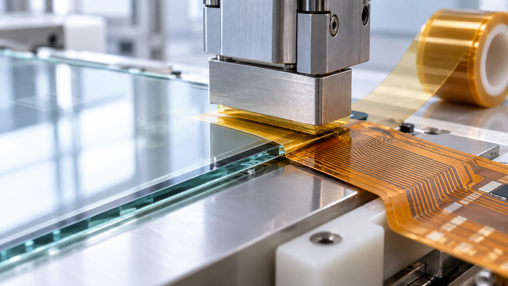
ACF is a film made of a thermosetting adhesive with conductive particles dispersed in it. Placed between two sets of electrodes and bonded under heat and pressure, it conducts only between the facing electrodes, while staying insulating sideways, and it glues the parts together at the same time. It is used to attach driver ICs and flexible circuits to display panels, and it can join parts where solder cannot be used, such as ITO electrodes, or where the parts cannot take high heat. This article walks through its structure, assembly formats, bonding conditions, fine-pitch evolution, evaluation and failure modes, using manufacturers' technical material and journal papers.
- What ACF is, in three lines
- Structure: adhesive plus conductive particles
- Why it conducts vertically and insulates sideways
- A materials engineer's view (1): why the particles are plated resin spheres, not metal balls
- Assembly formats: COG, COF, FOG, FOB and more
- The bonding sequence and the bonding conditions (temperature, pressure, time)
- A materials engineer's view (2): designing the race between flow and gelation
- Fine-pitch evolution: smaller particles, insulating coats, and placing particles in order
- Our calculation: why random dispersion leaves terminals short
- Evaluating connection reliability
- Connection failures: too few particles, short circuits, delamination
- A materials engineer's view (3): shrinkage is both the source of conduction and the source of peeling
- What is still hard, and what we could not confirm
- Glossary / References / Claim-to-source audit
Sourced = a statement in published material (link given)
Our calculation = a figure this article derived, with the assumptions spelled out
Not yet confirmed = a plan or target with no confirmed track record
Structural readings and materials-design interpretations are marked separately as Commentary.
Product figures are the manufacturer's stated values; values for different grades and test conditions are not lined up to rank one product above another.
1. What ACF is, in three lines
ACF stands for anisotropic conductive film (also called anisotropic conductive adhesive film). “Anisotropic” means that electrical conduction differs by direction.
- What it is: a film made of a thermosetting resin, typically epoxy, with conductive particles dispersed in it. After thermocompression bonding it conducts in the bonding direction (vertically) and insulates in the in-plane direction. This is Resonac's descriptionSourced
- What it does: Dexerials explains that ACF alone performs three functions: adhesion, conduction and insulation. It can connect many electrodes in one step, allows finer connection (fine pitch) than soldering, and can be assembled at low temperatures of about 110 to 180 °CSourced
- Where it is used: in flat-panel displays such as smartphones, tablets and TVs, to join IC chips and flexible circuits to the glass substrate. It is also used in camera modules and IC cardsSourced
The difficulty of ACF lies not in conduction but in balancing “trapping” against “insulation”. As terminals shrink and spacing narrows, getting enough particles onto each terminal and avoiding particles that join neighbouring terminals pull in opposite directions. The history of ACF over some 40 years is the history of resolving that conflict (this article's reading).
The chemistry of the adhesive itself (such as epoxy curing) is covered in our explainer on epoxy resins. For the thermal-expansion mismatch between chip and substrate, see our explainer on the coefficient of thermal expansion; for the liquid-resin approach of filling the gap under a chip, see our explainer on underfill.
2. Structure: adhesive plus conductive particles
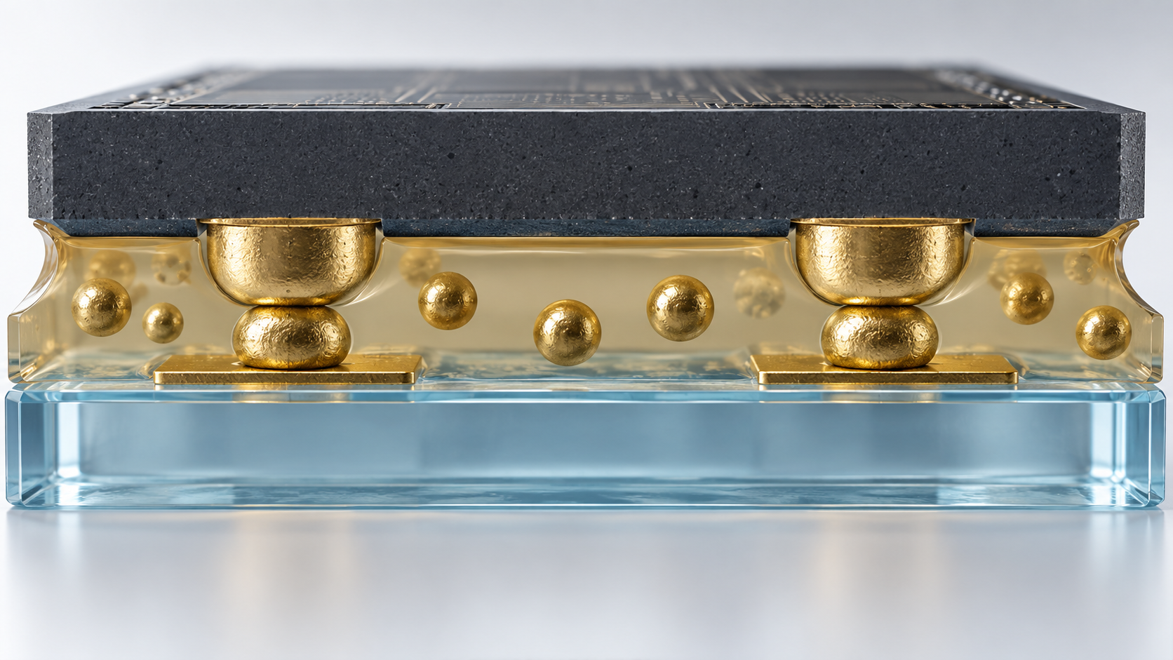
ACF is a layer of adhesive (the binder) with conductive particles scattered through it. The adhesive is a thermosetting epoxy or acrylic resinSourced [Ref. 1].
| Item | Published information (manufacturer's stated values, papers) | Source |
|---|---|---|
| Film thickness | Dexerials: 10 to 45 µm. Resonac: 10 to 45 µm | [Ref. 1, 6] |
| Width and length | Dexerials: width 0.5 to 20 mm, length 10 m up to 300 m. Resonac: width about 0.4 to 20 mm | [Ref. 1, 6] |
| Supply format | Reels. A three-layer type (film between a protective film and a release film) and a two-layer type (release film only) are offered (Dexerials) | [Ref. 1] |
| Conductive particles | Typically a resin core plated with nickel or gold and coated with an insulator (Dexerials). Resonac offers spherical resin particles coated with Ni, 3 to 20 µm in diameter, and also Au- or Pd-plated particles | [Ref. 1, 6] |
| Adhesive | Mostly thermosetting resins: acrylic, cationic epoxy, anionic epoxy and so on. Thermosetting types must be stored refrigerated (Resonac) | [Ref. 6] |
All Sourced (manufacturer's stated values; they differ by product grade).
How the conductive particles evolved
According to Dexerials, the conductive material in ACF has changed as followsSourced [Ref. 1, 3]. The first ACF used carbon fibre of about 100 µm; a few years later it moved to metal particles of 50 µm, about half the size. In 1988 resin particles plated with nickel or gold appeared, and in the 1990s a technique for coating the particle surface with an insulator was developed. Since then particle diameter has shrunk from 5 µm to 2.8 µm.
3. Why it conducts vertically and insulates sideways
When ACF is sandwiched between electrodes and bonded under heat and pressure, the adhesive first melts and flows, pushing away the resin that lay between the electrodes and the particles. Then the particles trapped between facing electrodes are crushed against the electrodes and form a conductive path. The insulating coat on the outermost surface of a particle breaks as it is crushed, and current flows.
Particles that are not trapped, on the other hand, move through the resin into the spaces between terminals, and their insulating coat stays intact. Adjacent terminals therefore do not become connectedSourced [Ref. 1]. Finally, the adhesive heat-cures and hardens, bonding, fixing and sealing the electrodes to each otherSourced [Ref. 6].
Watanabe of Hitachi Chemical (now Resonac) explains that the electrical contact between particle and electrode is secured by a balance between the restoring force of the elastically deformed particle and the cure-shrinkage force of the adhesiveSourced [Ref. 10]. Conduction is not finished once the particles are crushed: it is kept by the particle constantly pushing back on the electrode while the resin pulls the electrodes together, and the two staying in balance during use. This links to chapter 11 on connection failures and to the materials engineer's view in chapter 12.
4. A materials engineer's view (1): why the particles are plated resin spheres, not metal balls
When we hear “conductive particle”, we tend to picture a metal sphere. According to Watanabe (2005) of Hitachi Chemical, however, the early ACF did use Ni particles, but once displays needed pitches of 70 µm or less, metal particles clumped and could not ensure insulation, and connections to hard panel electrodes did not give sufficient reliabilitySourced [Ref. 10].
What was put into practical use instead was resin particles, close to the adhesive in density and thermal expansion, with a thin metal plating (3 to 10 µm in diameter)Sourced [Ref. 10]. From the materials side, three intentions can be read into this (our commentary).
- They deform: the resin core flattens under pressure, widening the contact area with the electrode. A hard metal sphere touches at a point.
- They recover: the crushed resin sphere tries to return to shape and keeps pushing back on the electrode. This is the “restoring force” of the previous chapter.
- They blend in: because density and thermal expansion are close to the adhesive's, they settle less in the resin and move with it as temperature changes. The idea of expansion mismatch is shared with our explainer on the coefficient of thermal expansion.
On the other hand, for joining metal electrodes to each other, nickel particles are still considered effective. Their surface is spiky (“chestnut-burr-like”), which suits breaking the oxide film on the electrode surfaceSourced [Ref. 10]. Particle hardness, shape and surface are chosen to match the electrode on the other side.
5. Assembly formats: COG, COF, FOG, FOB and more
The name of an assembly format changes with what is joined to what. In displays, the transparent electrodes (ITO) on the glass substrate must be connected to the driver IC. Resonac explains that ITO does not form a eutectic with solder, so solder joining cannot be usedSourced [Ref. 6]. That is where ACF comes in.
| Abbreviation | Full name | What joins to what | Typical use (as described in the sources) |
|---|---|---|---|
| COG | Chip on Glass | IC chip ↔ glass substrate | Medium and small displays; the IC is mounted directly |
| COF | Chip on Flex (Chip on Film) | IC chip ↔ flexible circuit | The IC is placed on the COF, which is then joined to the glass by FOG |
| FOG | Flex on Glass (Film on Glass) | Flexible circuit ↔ glass substrate | Narrow-bezel and bezel-less smartphones; also common in large displays |
| FOB | Flex on Board | Flexible circuit ↔ rigid printed circuit board | The input side of a display, for example |
| FOF | Flex on Flex | Flexible circuit ↔ flexible circuit | Not limited to displays |
| FOP | Flex on Plastic | Flexible circuit ↔ plastic substrate (PET, COP, CPI and so on) | Around touch sensors |
| COP | Chip on Plastic | IC chip ↔ plastic substrate | Flexible organic EL (OLED); Dexerials' description |
All Sourced (a table compiled from the descriptions of Resonac [Ref. 6] and Dexerials [Ref. 3]).
Beyond displays, Resonac says ACF is used for heat-sensitive parts such as CMOS and CCD image sensors in camera modules, for IC cards, micro LEDs and the secondary assembly of semiconductorsSourced [Ref. 6]. For micro LEDs, the company writes that “ACF assembly is being considered”, not as an achieved result. This article therefore treats application to micro LEDs as Not yet confirmed.
Dexerials organises its ACF product list by application: COG and FOG types for medium and small displays; FOG (glass substrate to COF) and FOB (COF to input board) types for large displays; an automotive FOB type (stated to comply with IATF 16949); IC cards; replacements for solder and connectors; and touch panelsSourced [Ref. 5].
Dexerials lists as limits of ACF that it is difficult to mount parts of different shapes at the same time, and that because it is an adhesive, parts cannot be freely attached and detached like a connectorSourced [Ref. 1].
6. The bonding sequence and the bonding conditions (temperature, pressure, time)
The assembly sequence is almost the same in the explanations of Dexerials and ResonacSourced [Ref. 1, 6].
- Clean the substrate: remove contamination from the bonding surface. For glass, cleanliness is maintained with alcohol or organic solvents, plasma cleaning or UV cleaning (Resonac).
- Laminate: attach the ACF to the substrate and apply heat and pressure with the separator (PET) film still on.
- Peel the separator: remove the film.
- Align: position the electrodes of the chip or flexible circuit over those of the substrate.
- Final bonding: apply heat and pressure again to join the parts.
As points to watch in thermocompression, Resonac lists temperature control of the heater head, keeping the head parallel to the glass substrate, and checking particle shape, resistance and adhesion after bondingSourced [Ref. 6].
Bonding conditions differ by product grade
Bonding conditions vary greatly with the ACF grade and the counterpart parts (heat resistance, electrode size). The table below shows the values Resonac lists as “mounting conditions” on its product pages. All are lower limits (≥), and all are manufacturer's stated values.
| Grade (manufacturer's stated) | Use | Minimum connection area | Minimum space | Temperature | Time | Pressure |
|---|---|---|---|---|---|---|
| AC-8000 series | IC chips | 600 µm² | 10 µm | ≥ 140 °C | ≥ 5 s | ≥ 40 MPa (per total electrode area) |
| AC-10000 series | COF | 3,000 µm² | 10 µm | ≥ 170 °C | ≥ 5 s | ≥ 3 MPa |
| AC-3000 series | FPC | 12,000 µm² | 15 µm | ≥ 160 °C | ≥ 5 s | ≥ 3 MPa |
| AC-7000 series | FPC | 29,000 µm² | 15 µm | ≥ 180 °C | ≥ 5 s | ≥ 3 MPa |
| AC-9000 series | COF | 50,000 µm² | 50 µm | ≥ 160 °C | ≥ 5 s | ≥ 3 MPa |
| AC-2000 series | FPC and COF | 50,000 µm² | 50 µm | ≥ 180 °C | ≥ 10 s | ≥ 3 MPa |
Resonac product pages [Ref. 7, 8]. Sourced (manufacturer's stated values). The IC-chip row carries a footnote saying the pressure is “per total electrode area”, but the FPC and COF rows have no footnote, so the reference area could not be confirmed. The substrates used for testing and the upper limits of time and temperature are not given on the pages.
As a general feature of ACF, Resonac says it “can be connected at low temperatures of about 100 to 240 °C and in short times of 4 to 60 seconds”Sourced [Ref. 6], and its MF series for solder replacement lists the same range (100 to 240 °C, 4 to 60 s) [Ref. 9]. The film-substrate product page gives “170 °C / 5 s” as an example of low-temperature, short-time bonding [Ref. 7].
Bonding conditions in a research paper
Here is also an example from an open-access, peer-reviewed paper. Fang et al. (2024) joined flexible circuits to each other (Flex on Flex) with a bonder (Finetech PICO 145), using two commercial ACFs: ACF-1 with particles of about 20 µm and ACF-2 with particles of about 5 µmSourced [Ref. 12].
| ACF (as named in the paper) | Temporary bonding | Final bonding (paper's standard condition) | Condition giving the best contact resistance in the low-pressure experiment |
|---|---|---|---|
| ACF-1 (particles about 20 µm) | 80 °C, 1 MPa, 2 s | 150 °C, 0.67 MPa, 15 s | 170 °C, 0.67 MPa (time as in the standard) |
| ACF-2 (particles about 5 µm) | 80 °C, 1 MPa, 2 s | 200 °C, 0.67 MPa, 10 s | 220 °C, 0.67 MPa (time as in the standard) |
Experimental conditions of Fang et al. (Materials, 2024) [Ref. 12]. Sourced (an experimental example; not the stated values of any specific product). The paper's text mixes a statement that the standard bonding pressure is “1 MPa” with “0.67 MPa” in its table, so this article shows the table values.
The pressure for Resonac's IC-chip ACF (AC-8000 series) is “40 MPa or more (per total electrode area)”. Converting it to forceOur calculation:
- One terminal of the minimum connection area: 40 MPa × 600 µm² = 40×10⁶ N/m² × 600×10⁻¹² m² = 2.4×10⁻² N = about 24 mN
- For an IC with a total electrode area of, say, 2 mm²: 40 MPa × 2 mm² = about 80 N (about 8 kgf)
Assumptions and limits: the “per total electrode area” pressure was treated as a pressure spread evenly over the electrode area. In reality the force per terminal is not uniform because of head parallelism, chip warpage and the presence of a cushion. The 2 mm² total electrode area is a made-up value of ours, not that of a real IC.
7. A materials engineer's view (2): designing the race between flow and gelation
On the connection of thermosetting ACF, Watanabe (2005) of Hitachi Chemical says, in essence, the followingSourced [Ref. 10].
- A thermosetting adhesive flows on heating, but it starts to gel quickly.
- So unless the specified pressure (usually 2 to 3 MPa) is applied while it is flowing, the adhesive between particle and electrode cannot be pushed out, and an electrical connection through the conductive particle cannot be secured.
- It is therefore important to control the process so that pressure can be applied while the adhesive is flowing, at the same time as the heating needed to cure the ACF.
Read from the materials side, this is a race between “flowing” and “setting” (our commentary). Once heating starts, the resin's viscosity first falls so that it flows, and then cure reactions proceed and viscosity rises sharply. If the resin on top of the electrodes cannot be cleared while viscosity is low, the particles never reach the electrodes. Dexerials measures the reaction rate by FT-IR, saying that if it is lower than expected the heat energy needed for curing was insufficient [Ref. 4]; this can be read as a way of checking the outcome of this race.
Another design problem is combining “fast cure” with “long storage life”. The same paper says that to use a thermosetting adhesive in ACF, one needs fast curing, so that connection takes only several seconds to about 20 seconds of heat and pressure, and, for workability, a pot life of two weeks or more at room temperature. The authors state that with an epoxy system containing a dispersed latent curing agent they achieved both fast cure at 170 °C in 15 to 20 seconds and a pot life of a month or more at room temperatureSourced [Ref. 10]. Even so, Resonac says thermosetting ACF must be stored refrigerated [Ref. 6], and Dexerials explains that thermosetting types cure progressively even when just left at room temperature, so storage at the specified temperature is required [Ref. 4].
One route to lower temperatures is a radical-curing system such as acrylate. The paper introduces an example that achieved a reduction of about 30 °C compared with epoxy curing systemsSourced [Ref. 10]. For the basics of the cure mechanisms (amines, acid anhydrides, latent curing agents), see our explainer on epoxy resins.
8. Fine-pitch evolution: smaller particles, insulating coats, and placing particles in order
As displays moved to higher resolution, the spacing (pitch) between electrodes narrowed year by year. Dexerials writes that in high-definition mobile displays the distance between IC chip electrodes has been reduced to 10 µmSourced [Ref. 1]. Resonac states that earlier films using carbon fibre as the conductive particle could handle pitches of only 500 µm or more, but that using metal particles it put ACF into practical use in small LCD TVs in 1984, reached 100 µm or less in 1992, and now achieves 20 µm with its ANISOLMSourced [Ref. 6].
| Approach | What it does | What the sources say |
|---|---|---|
| 1. Smaller particles | Make particles smaller so they fit less easily between terminals | Dexerials: particle diameter from 5 µm to 2.8 µm [Ref. 1] |
| 2. Insulation-coated particles | Cover the particle surface with an insulator so that touching particles do not connect | Developed in the 1990s (Dexerials) [Ref. 1, 3]; also used for narrow-pitch COG (Resonac) [Ref. 10] |
| 3. Two-layer construction | Stack a particle-containing layer and an adhesive-only layer so particles gather on the electrodes more easily | Resonac: particle trapping improved to about twice that of a single layer [Ref. 10] |
| 4. Aligning the particles | Place particles at set positions and fix them there | Dexerials' “ArrayFIX” (launched in 2016) [Ref. 2, 3]; Resonac's “Particle-Aligned ACF (PAL-ACF)” (announced in 2016) [Ref. 6] |
All Sourced (the companies' published material; the grouping into four is this article's own).
Why simply adding particles reached a dead end
Conventional ACF disperses particles in the resin. Dexerials says that raising the number of particles per area raises the chance that a terminal traps them, but as display resolution rose, that approach was reaching its limit from around the 2010s. This is because too many particles clog the spaces between terminals, raising the risk of short circuitsSourced [Ref. 2].
The answer was “not to add particles but, on the contrary, to reduce them and arrange them regularly at intended positions”Sourced [Ref. 2]. Arranging them is not enough by itself. In conventional ACF the particles moved within the heated, pressurised resin and escaped into the spaces between terminals, so for the aligned type a resin that suppresses flow so that particles do not move was also developed. Because the particles hardly move during bonding, the short-circuit risk can be reduced too, as the explanation goesSourced [Ref. 2].
| Item | Conventional ACF | Particle-aligned ACF | Change |
|---|---|---|---|
| Amount of particles | 60,000 | 28,000 | 53% fewer |
| Minimum connection area | 1,300 µm² | 300 µm² | 77% smaller |
| Minimum terminal spacing | 12 µm | 10 µm | 17% narrower |
Comparison values from the Dexerials explanation [Ref. 2]. Sourced (manufacturer's stated values). The page does not state the products compared, the test conditions, or the unit of the particle amount (per area or total count). The page prints the unit of the spacing as “µm²”, but elsewhere on the same page it says “minimum bump spacing 10 µm”, so this article reads it as µm (our commentary).
The aligned type also has design advantages. According to Dexerials, in conventional ACF the number of particles trapped per terminal follows something like a normal probability distribution, whereas the aligned type has particle positions designed in advance, so trapping is extremely stable. As a result, wiring and terminal designs can be examined on a computer without building trial devicesSourced [Ref. 3]. Dexerials also says the aligned type can use existing ACF assembly equipment as is, so no new capital investment is needed [Ref. 2]. It adds that demand is growing for flexible OLED displays that require COP (Chip on Plastic) connections [Ref. 3].
9. Our calculation: why random dispersion leaves terminals short
Let us check, with simple statistics, that “scattering particles in resin makes the number on each terminal vary”Our calculation.
- Assumption 1: particles land on a terminal at random, and the number N trapped per terminal follows a Poisson distribution (mean λ)
- Assumption 2: three or more trapped particles are enough. The “three or more” is borrowed from Watanabe (2005): with Au bumps of 50 µm square and particles of 4 µm diameter, in a temperature-cycling test (−40 °C / 100 °C, 500 cycles), contact resistance stabilised once there were three or more particlesSourced [Ref. 10]
- Assumption 3: the IC has 1,000 terminals
The probability that a terminal traps fewer than three particles is P(N≤2) = e−λ(1 + λ + λ²/2). For λ = 10, for example, P = e−10 × (1 + 10 + 50) = about 0.28%. The probability that at least one of the 1,000 terminals is short is 1 − (1 − P)1000 = about 94%. Raising λ to 15 drops P to about 0.0039%, and the chance that any of the 1,000 terminals is short falls to about 3.8%.
Assumptions and limits: real particles move as the resin flows, and the number needed also changes with bump shape and particle size even for the same terminal size. λ and the terminal count are made-up values of ours, not the particle counts of any real product. The Poisson distribution used here is not the same as the “something like a normal distribution” Dexerials mentions, though the two look similar when the mean is large (our commentary).
What this calculation shows is that to guarantee “every terminal passes” with random dispersion, the mean number trapped must be raised to many times the required number (here, three). But the more the mean is raised (the more particles are added), the more particles also sit between terminals, and the short-circuit probability rises. Alignment can be seen as a way of resolving this trade-off between “trapping” and “insulation” by design instead of by statistics (our commentary).
10. Evaluating connection reliability
For an ACF connection, it is not enough to know that it “is connected”: one must check that it “stays connected”. Dexerials lists the following items in its analysis flow when trouble occursSourced [Ref. 4].
| Evaluation item | What is examined | Method or condition (example) | Source |
|---|---|---|---|
| Appearance | Before bonding: bubbles, peeling of the protective film, degradation. After bonding: voids, foreign matter, indentation marks, particle dispersion | Metallurgical microscope and similar | [Ref. 4] |
| Reaction rate | Whether the adhesive cured as expected | Infrared absorption measured by FT-IR (for both epoxy and acrylic types) | [Ref. 4] |
| Cross-section | Whether particles are crushed properly and conduct; whether particles between terminals stay insulating | Cross-section ground away with a grinder and observed; with particles of 3 µm or less, cutting the section correctly takes skill | [Ref. 4] |
| Adhesion | Whether it holds with the expected force; how it fails (failure mode) | COG is measured in the horizontal (shear) direction; FOG in both horizontal and vertical directions | [Ref. 4] |
| Foreign matter | Composition and origin of contamination | FT-IR (organics), SEM and EDX (inorganics) | [Ref. 4] |
| Storage condition | Whether it was stored at the specified temperature | Interview with the user | [Ref. 4] |
| Contact and insulation resistance | Electrical performance for conduction and insulation | Paper example: contact resistance measured at 10 mA was below 1 Ω; insulation resistance measured at 20 V was on the order of 10¹² Ω | [Ref. 12] |
| Temperature-cycling test | Contact resistance after repeated temperature swings | Paper example: −40 °C / 100 °C, 500 cycles | [Ref. 10] |
| High-temperature, high-humidity test | Interface delamination after moisture exposure | Paper example: 85 °C / 85% RH, 500 hours | [Ref. 10] |
| Bending test | Change in electrical properties in flexible uses | Paper example: bending radius 1 mm, 2 s per cycle, cycle counts set in the range 10 to 5,000 | [Ref. 12] |
All Sourced (Dexerials' analysis procedure [Ref. 4] and experimental conditions in papers [Ref. 10, 12]). The conditions in the papers are settings of specific experiments; they are not test conditions defined by a standard.
The paper states that the bending test of Fang et al. (2024) followed the Chinese national standard GB/T 38001.61-2019 (written in the paper as “Mechanical Stress Test Method for flexible display parts”)Sourced [Ref. 12]. Separately, the IEC web store lists IEC 62715-6-1 (Flexible display devices - Part 6-1: Mechanical test methods - Deformation tests; second edition, published 20 April 2018), an international standard for the mechanical stability of flexible display modules against bending, rolling, twisting and stretchingSourced [Ref. 13]. This article has not confirmed how GB/T 38001.61 and IEC 62715-6-1 correspond. We could not confirm the number of any international standard (IEC, JIS and so on) specific to evaluating ACF, so none is given here.
11. Connection failures: too few particles, short circuits, delamination
ACF failures can be grouped into three broad kinds (this article's grouping).
| Symptom | Causes and background given in the sources | How it is checked |
|---|---|---|
| Too few trapped (open circuit) | As terminals get smaller, fewer particles land on them. In COG the chip's bumps are the terminals, so the connection area is about one tenth of a TCP connection, and trapping enough particles on electrodes of roughly 2,000 to 2,500 µm² was a challenge [Ref. 10]. If the ACF resin is not cleared sufficiently, particles do not reach the electrode (chapter 7) | Cross-section observation, contact-resistance measurement [Ref. 4] |
| Short circuit | Adding too many particles clogs the spaces between terminals [Ref. 2]. Metal particles could also clump and fail to ensure insulation [Ref. 10] | Insulation-resistance measurement, cross-section observation |
| Delamination | In COG, as ICs grew larger the stress on the bonded interface increased, and interface delamination occurred after a high-temperature, high-humidity test (85 °C / 85% RH, 500 hours) [Ref. 10]. Insufficient cleaning of the substrate surface raises the risk of delamination [Ref. 6]. With ACF of smaller particles, finite-element analysis and experiments report that the plating cracks under bending stress and the particles peel more easily from the electrode pad [Ref. 12] | Adhesion and failure mode; observation after high-temperature, high-humidity tests [Ref. 4, 10] |
| Insufficient cure | If the reaction rate is lower than expected, the heat energy needed for curing was insufficient [Ref. 4]. Temperature control of the heater head and its parallelism to the substrate also matter [Ref. 6] | Reaction rate by FT-IR |
| Foreign matter and voids | Dexerials says the most common trouble after bonding of adhesive materials is contamination by foreign matter [Ref. 4]. Voids are also checked by appearance | Metallurgical microscope, FT-IR, SEM and EDX |
| Degradation from poor storage | Thermosetting types cure progressively even when just left at room temperature. If storage was not appropriate, the same trouble recurs [Ref. 4] | Interview about storage conditions |
All Sourced (a summary of the statements in each source; the causes are examples the sources give, not an exhaustive list).
The difficulty of rework
When rework after assembly is anticipated, Dexerials recommends acrylic-resin ACF. Cured epoxy does not dissolve in solvents, so the residue has to be scraped off, and in many cases this damages the substrate. After final bonding, the bonded area is warmed with a heat gun or hot plate and the FPC is peeled off, and resin left between the wiring on the substrate is removed with a solvent such as MEK or NMP and a cotton swab. However, FPCs often curl and cleaning the resin between wiring on the FPC side is difficult, so the company does not recommend reusing the FPCSourced [Ref. 1]. The company adds that it does not itself recommend rework, and urges doing it only after confirming through reliability evaluation that there is no problem.
Resonac likewise says that its strongly adhesive acrylic-based grades are well established for connections to FPC (FOG, FOB, FOF, FOP), and points to anionic-epoxy grades as the contamination-tolerant type. For both, it says that with a suitable choice of organic solvent, peeling and removal conditions for rework can be foundSourced [Ref. 6].
12. A materials engineer's view (3): shrinkage is both the source of conduction and the source of peeling
In the summary of a 2003 paper on the reliability of joints made with ACF, Won-Keun Kim, Toru Ikeda and Noriyuki Miyazaki (Kyushu University) state the followingSourced [Ref. 11].
- A joint made with ACF generates pressure between the bumps through shrinkage of the resin, and this secures conduction.
- At the same time, the shrinkage of the resin is also a driving force that peels the joint from the semiconductor chip or substrate.
- A design that balances the two is therefore needed.
The authors propose a method of evaluating joint strength using the stress intensity factor of an interface crack between dissimilar materials, and report that the residual stress at the chip-ACF interface is higher than at the ACF-substrate interface [Ref. 11].
This is the flip side of the “balance between the particle's restoring force and the adhesive's cure-shrinkage force” seen in chapter 3 (our commentary). Raising the shrinkage force presses particles harder onto the electrodes and stabilises conduction, but it also raises the stress left at the interface, which becomes a starting point for delamination when moisture or temperature change is added. The adjustments available on the materials side can be summarised as follows.
- Lower stress: for an example in which a large IC in COG showed interface delamination after a high-temperature, high-humidity test, Watanabe (2005) says lowering the stress of the ACF is effective for adhesion, and shows that with a low-stress type there was no interface delamination after the same test (85 °C / 85% RH, 500 hours) [Ref. 10].
- Lower modulus and filler loading: for flip-chip assembly on organic substrates, the key to reliability is reducing the stress from the thermal-expansion difference between IC and substrate, and lowering the adhesive's modulus, and lowering expansion and water absorption by loading filler, have been studied [Ref. 10].
The idea that an expansion difference turns into stress is shared with our explainers on the coefficient of thermal expansion, the idea of filler loading and interfaces with our explainer on polymer blends and fillers, and the idea of sealing under a chip with our explainer on underfill. ACF differs from those materials, however, in that pressure is needed for conduction.
- ACF is a thermosetting adhesive film that handles adhesion, conduction and insulation in one sheet. Only the particles trapped between facing electrodes are crushed and conductSourced
- The conductive particles are mostly plated resin spheres, not metal balls. They deform to gain contact area and push back on the electrode by their restoring forceSourced
- Bonding conditions differ by grade. In Resonac's published values, temperatures are 140 to 180 °C or more, times 5 s or more, and pressure 3 MPa or more for FPC and COF typesSourced
- The difficulty is the race between “flowing” and “setting”, and balancing “trapping” with “insulation”. Alignment solves the latter by designSourced
- With random dispersion, even at a mean of 10 particles, the chance that at least one of 1,000 terminals has fewer than 3 is about 94%Our calculation
- Shrinkage force is a source of conduction and also a source of peeling. Lowering stress is one adjustment leverSourced
13. What is still hard, and what we could not confirm
(1) The material and thickness of the insulating coat could not be confirmed
Dexerials writes that the outermost surface of the particle is “coated with an insulator” [Ref. 1], but the coat's material and thickness could not be confirmed in the public sources used, so they are not stated here. Fig. 2 shows the coat conceptually as a thin outline.
(2) Only lower limits of the bonding conditions could be confirmed
Resonac's product pages give “or more (≥)” values, and recommended upper limits and the reference area of the pressure for FPC and COF types could not be confirmed. The Dexerials product list page [Ref. 5] did not give individual bonding conditions. Actual conditions presuppose an inquiry to the manufacturer and determination by evaluation; Resonac too says it takes consultations on the temperature and time settings for thermocompression [Ref. 6].
(3) Evaluation standards and pass criteria could not be confirmed
The temperature-cycling and high-temperature, high-humidity conditions shown here are examples from papers. The numbers of standards for evaluating ACF connection reliability, and their pass criteria, could not be confirmed within the scope of this survey.
(4) A standard particle areal density could not be confirmed
The Dexerials comparison values (60,000 to 28,000) carry no unit. Because a typical areal density of particles could not be confirmed in public material, the calculation in chapter 9 uses made-up mean counts.
(5) New uses such as micro LED are a matter for the future
Resonac writes that ACF assembly for micro LEDs “is being considered” [Ref. 6]. There are also reports of ACF with particle diameters in the 2 µm range being developed, but this article stays within what could be confirmed in primary sources (the manufacturers' official material) and does not cover them hereNot yet confirmed.
(6) No market size or share figures are used
Market size and manufacturer share for ACF appear in market-research estimates and press reports. This article does not use them.
14. Glossary
- ACF
- Anisotropic Conductive Film. A film-type joining material with conductive particles dispersed in a thermosetting resin.
- Anisotropy
- Properties that differ by direction. In ACF: conductive vertically, insulating in the plane.
- Bump
- A protruding terminal formed on an IC chip's electrode. Gold and similar metals are used.
- ITO
- Indium tin oxide. Used for transparent electrodes in displays. Does not form a eutectic with solder.
- COG
- Chip on Glass. Mounting an IC chip directly on a glass substrate.
- COF
- Chip on Flex (Film). Mounting an IC chip on a flexible circuit.
- FOG
- Flex on Glass (Film on Glass). Joining a flexible circuit to a glass substrate.
- FOB
- Flex on Board. Joining a flexible circuit to a printed circuit board.
- FOF / FOP / COP
- Joining flexible circuit to flexible circuit / flexible circuit to plastic substrate / IC chip to plastic substrate.
- FPC
- Flexible printed circuit. A thin wiring board that can be bent.
- Fine pitch
- Very narrow spacing between electrodes. Pitch is the centre-to-centre distance.
- Trapping
- A conductive particle being caught between facing electrodes and used for the connection.
- Insulation-coated particle
- A conductive particle whose surface is covered with an insulator. The coat breaks when the particle is crushed, allowing conduction.
- Gelation
- When a thermosetting resin loses flowability through the cure reaction and becomes jelly-like.
- Pot life
- How long a mixed or stored material stays usable.
- Latent curing agent
- A curing agent that does not react at room temperature and starts to react on heating. Combines storage stability with fast cure.
- Heater head
- The part of a thermocompression machine that applies heat and pressure.
- Poisson distribution
- A probability distribution describing the scatter in the count of rare events. Used in our calculation.
- FT-IR
- Fourier-transform infrared spectroscopy. Examines reaction rate and the composition of contaminants from functional-group absorption.
- ArrayFIX / PAL-ACF / ANISOLM
- Brand names: Dexerials' particle-aligned ACF, Resonac's particle-aligned ACF, and Resonac's ACF line.
15. References
- Dexerials "Basic knowledge of Anisotropic conductive film (ACF)", TECH TIMES, 25 November 2020 (last updated 30 January 2024) — techtimes.dexerials.jp
- Dexerials "Basics of ArrayFIX, a particle-aligned ACF", TECH TIMES, 25 November 2020 (Japanese-language page) — techtimes.dexerials.jp
- Dexerials "ArrayFIX, a particle-aligned ACF: its advantages and expanding market", TECH TIMES, 17 January 2022 (Japanese-language page) — techtimes.dexerials.jp
- Dexerials "Dexerials' Inspection Process supports cutting-edge Anisotropic conductive film (ACF) mounting", TECH TIMES, 25 November 2020 — techtimes.dexerials.jp
- Dexerials "Anisotropic Conductive Film (ACF) and Conductive Film Product List", product page — dexerials.jp
- Resonac "What is ACF (Anisotropic Conductive Film)? Its usages, how to apply, types, and more are explained." — resonac.com
- Resonac "ACF (Anisotropic Conductive Film) for Film Substrate Connections", product page (AC series) — resonac.com
- Resonac "ACF (Anisotropic Conductive Film) for IC Chip Connections", product page (AC-8000 series) — resonac.com
- Resonac "ACF (Anisotropic Conductive Film) for Solderless Connections", product page (MF series) — resonac.com
- Itsuo Watanabe (Hitachi Chemical Co., Ltd.) "Anisotropic Conductive Adhesive Films", Materials Application Course No. 2, Journal of Japan Institute of Electronics Packaging, Vol. 8, No. 4, pp. 346-351, 2005 (DOI 10.5104/jiep.8.346; Japanese-language PDF hosted on the Resonac site) — resonac.com
- Won-Keun Kim, Toru Ikeda and Noriyuki Miyazaki (Kyushu University) "Evaluation of Reliability of a Joint Using Anisotropic Conductive Adhesive", Journal of Japan Institute of Electronics Packaging, Vol. 6, No. 2, pp. 153-160, 2003 (DOI 10.5104/jiep.6.153); abstract page, in Japanese and English — jiep.or.jp
- Fang Y. et al. "Size Effects of Au/Ni-Coated Polymer Particles on the Electrical Performance of Anisotropic Conductive Adhesive Films under Flexible Mechanical Conditions", Materials 2024, 17(7), 1658 (DOI 10.3390/ma17071658); open access (PMC) — ncbi.nlm.nih.gov
- IEC (International Electrotechnical Commission) IEC 62715-6-1:2018 "Flexible display devices - Part 6-1: Mechanical test methods - Deformation tests", web store page (title and scope only checked) — webstore.iec.ch
16. Claim-to-source audit
| Claim in the text | Basis | Label |
|---|---|---|
| That ACF is a film of conductive particles in a thermosetting resin that conducts vertically and insulates in the plane after thermocompression bonding; film thickness 10 to 45 µm and width about 0.4 to 20 mm; connection at about 100 to 240 °C in 4 to 60 s; that ITO does not form a eutectic with solder so solder cannot be used; the definitions of COG, FOG, COF, FOB, FOF and FOP; the 1984 practical use in LCD TVs, the 500 µm or more pitch of carbon-fibre films, 100 µm or less in 1992, PAL-ACF (announced 2016), and ANISOLM at 20 µm pitch and 0.4 mm width; constant-heat and pulse-heat methods; the heater-head points to watch (temperature control, parallelism, checks after bonding); conductive particles (Ni-coated resin spheres of 3 to 20 µm diameter; Au and Pd plating); mostly thermosetting types needing refrigerated storage; acrylic and anionic-epoxy grades and rework | Reference 6 https://www.resonac.com/solution/tech/acf.html | Sourced |
| The 1977 commercialisation; the three functions of adhesion, conduction and insulation; low-temperature assembly at about 110 to 180 °C; the typical particle structure (resin core, Ni or Au, insulating coat) and that untrapped particles stay insulating; film thickness 10 to 45 µm, width 0.5 to 20 mm, length 10 to 300 m; three-layer and two-layer types; the five assembly steps; electrode distance reduced to 10 µm; that parts of different shapes are hard to mount together and cannot be detached; the history of conductive material (about 100 µm carbon fibre, 50 µm metal particles, plated resin particles in 1988, insulating coats in the 1990s, particle size from 5 to 2.8 µm); the acrylic-ACF recommendation for rework, the procedure, and the non-recommendation of reusing FPCs | Reference 1 https://techtimes.dexerials.jp/en/bonding/what-is-acf/ | Sourced |
| The limit of simply adding particles (short-circuit risk); the idea of reducing and aligning particles; the flow-suppressing resin; particle amount 60,000 to 28,000 (53% fewer), minimum connection area 1,300 to 300 µm² (77% smaller), minimum terminal spacing 12 to 10 µm (17%); that existing equipment can be used | Reference 2 https://techtimes.dexerials.jp/bonding/what-is-paf/ | Sourced |
| The definitions of COG, FOG and FOB; the 2016 launch of ArrayFIX; that the number of particles trapped by conventional ACF follows something like a normal distribution and can be predicted for the aligned type; demand for COP connections; the three series PAF300, 400 and 700 | Reference 3 https://techtimes.dexerials.jp/bonding/advantage-of-paf/ | Sourced |
| The analysis items (appearance, FT-IR reaction rate, cross-section, shear direction for COG and horizontal and vertical directions for FOG, FT-IR, SEM and EDX for foreign matter, storage condition); that cutting sections takes skill for particles of 3 µm or less; that foreign matter is the most common trouble after bonding; that thermosetting types cure even at room temperature and need storage at a specified temperature | Reference 4 https://techtimes.dexerials.jp/en/bonding/dxc-analysis/ | Sourced |
| The application-based grouping of the Dexerials product list (COG, FOG, FOB, automotive, IC card, solder and connector replacement, touch panel) and the IATF 16949 compliance statement | Reference 5 https://www.dexerials.jp/en/products/acf/ | Sourced |
| Resonac mounting conditions (AC-8000 series ≥ 140 °C, ≥ 5 s, ≥ 40 MPa; AC-10000 ≥ 170 °C; AC-3000 ≥ 160 °C; AC-7000 ≥ 180 °C; AC-9000 ≥ 160 °C; AC-2000 ≥ 180 °C, ≥ 10 s; ≥ 3 MPa for FPC and COF types), minimum connection area and minimum space, the “170 °C / 5 s” example, and 100 to 240 °C and 4 to 60 s for the MF series | Reference 7 https://www.resonac.com/products/semi-backend-process/77/001.htmlReference 8 https://www.resonac.com/products/semi-backend-process/77/002.htmlReference 9 https://www.resonac.com/products/semi-backend-process/77/004.html | Sourced |
| That ACF was commercialised in 1984; how plated resin particles (3 to 10 µm, density and thermal expansion close to the adhesive) came into use at pitches of 70 µm or less; that the spiky surface of Ni particles helps break oxide films; the connection mechanism (balance of the particle's restoring force and the adhesive's cure shrinkage); flow and gelation of thermosetting adhesive and the usual 2 to 3 MPa pressure; fast cure (several seconds to 20 s) with a room-temperature pot life of two weeks or more; 170 °C for 15 to 20 s and a month or more at room temperature with a latent-curing-agent epoxy; about 30 °C lower with a radical-curing system; stable contact resistance with three or more particles after temperature cycling (−40 °C / 100 °C, 500 cycles); COG connection area about one tenth of TCP (2,000 to 2,500 µm²), about twice the trapping with a two-layer construction, insulation-coated particles; the 85 °C / 85% RH, 500 h delamination example and the improvement with low-stress ACF; lower modulus and filler loading for flip-chip assembly on organic substrates | Reference 10 https://www.resonac.com/sites/default/files/2022-12/solution_ACF01.pdf | Sourced |
| That in an ACF joint resin shrinkage generates pressure between bumps and secures conduction, while also being a driving force for peeling from chip or substrate; the result that residual stress at the chip-ACF interface is higher than at the ACF-substrate interface | Reference 11 https://www.jiep.or.jp/old/publish/journal/pdf/62/62a04.pdf | Sourced |
| The temporary and final bonding conditions of two commercial ACFs (particles about 20 µm and 5 µm): 80 °C, 1 MPa, 2 s; 150 °C, 0.67 MPa, 15 s; 200 °C, 0.67 MPa, 10 s; the best conditions in the low-pressure experiment (170 and 220 °C, 0.67 MPa); contact resistance below 1 Ω, insulation resistance about 10¹² Ω; the bending-test conditions; the result that smaller particles are more prone to plating cracks and peeling; the bending test following GB/T 38001.61-2019 | Reference 12 https://www.ncbi.nlm.nih.gov/pmc/articles/PMC11012521/ | Sourced |
| The title of IEC 62715-6-1:2018 (Flexible display devices - Part 6-1: Mechanical test methods - Deformation tests), its scope (bending, rolling, twisting, stretching), and the second edition published 20 April 2018 | Reference 13 https://webstore.iec.ch/publication/59479 | Sourced |
| Application of ACF to micro LEDs (the statement that “ACF assembly is being considered”) | Reference 6 https://www.resonac.com/solution/tech/acf.html | Not yet confirmed |
| 40 MPa × 600 µm² = about 24 mN, and about 80 N (about 8 kgf) for a total electrode area of 2 mm². Poisson probabilities of fewer than 3 (λ = 8, 10, 12, 15, 20) and of any of 1,000 terminals being short (about 100%, 94%, 41%, 3.8%, 0.05%) | Our calculation. That pressure is spread evenly over the electrode area, that trapped counts follow a Poisson distribution, that 3 or more is enough, 1,000 terminals, and a 2 mm² total electrode area are all our assumptions. The “3 or more” is a provisional threshold borrowed from the example in Watanabe (2005) | Our calculation |
| The material and thickness of the particles' insulating coat | Not confirmed in the public sources used, so not stated (our note) | Commentary |
| Upper limits of Resonac's bonding conditions, and the reference area of the pressure for FPC and COF types | The product pages give lower limits (≥) only and no footnote, so this could not be confirmed (our note) | Commentary |
| The number and pass criteria of any standard for evaluating ACF connection reliability, and the correspondence between GB/T 38001.61-2019 and IEC 62715-6-1 | Not confirmed within the scope of this survey, so not stated (our note) | Commentary |
| A standard particle areal density, and the unit and conditions of the Dexerials comparison (60,000 to 28,000) | Not given on the company's page, so not confirmed. The spacing unit is printed there as “µm²”, but the same page says “minimum bump spacing 10 µm”, so this article reads it as µm (our note) | Commentary |
| That the conductive particles are plated resin spheres with three intentions (deform, recover, blend in); the framing as a race between flowing and setting; that alignment resolves the trade-off between trapping and insulation by design; that shrinkage force is a source of both conduction and peeling; the grouping of failures into three kinds; the grouping of approaches into four | Commentary: this article's own organisation and interpretation of the published content; not views stated by the companies or institutions | Commentary |
| That the hero image and Fig. 1 are AI-generated images and that Figs. 2 to 7 are explanatory drawings | Our own note in this article | Commentary |
Last updated: 3 October 2026. Sources are limited to primary material (manufacturers' official technical material and product pages, journal and peer-reviewed papers, and standards bodies' pages). Because this article includes structural readings and materials-design interpretations, these are labelled “Commentary” and kept separate from sourced facts. Product figures are the manufacturer's stated values; values for different grades and test conditions are not lined up to rank products. The material and thickness of the particles' insulating coat, the upper limits of the bonding conditions and the reference area of the pressure, the evaluation standards and pass criteria for ACF, and a standard value of particle areal density could not be confirmed in published primary sources and are therefore not stated. Fig. 1 and the hero image are AI-generated images; Figs. 2 to 7 are vector drawings (Fig. 6 includes our calculation), and none of them shows an actual cross-section photograph, micrograph or real product.