TECHNOLOGY EXPLAINER
Barrier Properties and Coatings
— "impermeable" is not a property of the material but a number with conditions attached
From food packaging to electronic materials, polymers are asked to keep gases and water vapour out. Permeation is a process in which a molecule dissolves, spreads through the film, and emerges on the other side, so the same film can give very different numbers depending on temperature, humidity and whether the film has pinholes. This article walks through how permeation works, the measurement standards, EVOH, PVDC, inorganic vapour-deposited layers and multilayer films, and then coatings and VOC regulation, from a materials engineer's point of view.
- What barrier performance is (the short version)
- How permeation works — dissolution and diffusion
- Measurement standards — the same "permeability" can mean different methods and conditions
- A materials engineer's view (1): a number only means something together with its conditions
- The materials that provide the barrier — EVOH, PVDC, inorganic deposition, multilayer films
- Our calculation: how much oxygen enters through an EVOH layer in a year
- Defects decide permeation — inorganic thin-film barriers
- A materials engineer's view (2): film performance is sometimes set by the holes, not the material
- Coatings — solvent-borne, water-borne and UV-cured
- VOC regulation — where does the solvent go?
- A materials engineer's view (3): regulation becomes a constraint on material choice
- What is still hard, and what we could not confirm
- Glossary / References / Claim-to-source audit
Sourced = content stated in published material from a standards body, paper, company or public agency (link given)
Our calculation = a figure this article derived, with the assumptions spelled out
Not yet confirmed = a plan, target or outlook with no confirmed track record
Structural readings and materials-design interpretations are marked separately as Commentary.
Property values are manufacturers' stated values or values from papers, and are always shown together with the test method, temperature, humidity and thickness. Values for different grades are not lined up to rank them.
1. What barrier performance is (the short version)
- What is measured: how fast a gas (oxygen, say) or water vapour passes through a film or sheet, expressed as a transmission rate. ISO 15105-2 defines how to measure gas transmission rate for every form of plastic material, including films, sheets, laminates, co-extruded materials and flexible plastic-coated materialsSourced
- How it passes through: the basic picture is that a gas or vapour first dissolves into the surface of the polymer, spreads through the film down a concentration difference, and leaves from the other side (the solution-diffusion model; our commentary)
- What makes it hard: transmission rate shifts strongly with temperature, humidity, film thickness and film defects. EVOH becomes more permeable as humidity rises, and for inorganic thin films the performance is sometimes set by pinholes rather than by the material itselfSourced (Sections 5 and 7)
A figure such as "the oxygen transmission rate of this film is X" is not usable information on its own. Zhang et al.'s study of EVOH reports that, for both oxygen and water vapour, the transmission rate changes markedly with temperature and relative humidity, and rises sharply above 75% relative humiditySourced. Barrier performance is not a constant of the material; it is a performance that is fixed together with the environment of use (our commentary).
The orders of magnitude of water vapour transmission demanded for sealing perovskite solar cells, and water ingress from the edges, are covered in detail in the "Encapsulation and barrier layers" explainer in our perovskite solar cell series. This article does not repeat that material and sticks to the barrier mechanism, materials and coatings from the polymer point of view.
2. How permeation works — dissolution and diffusion
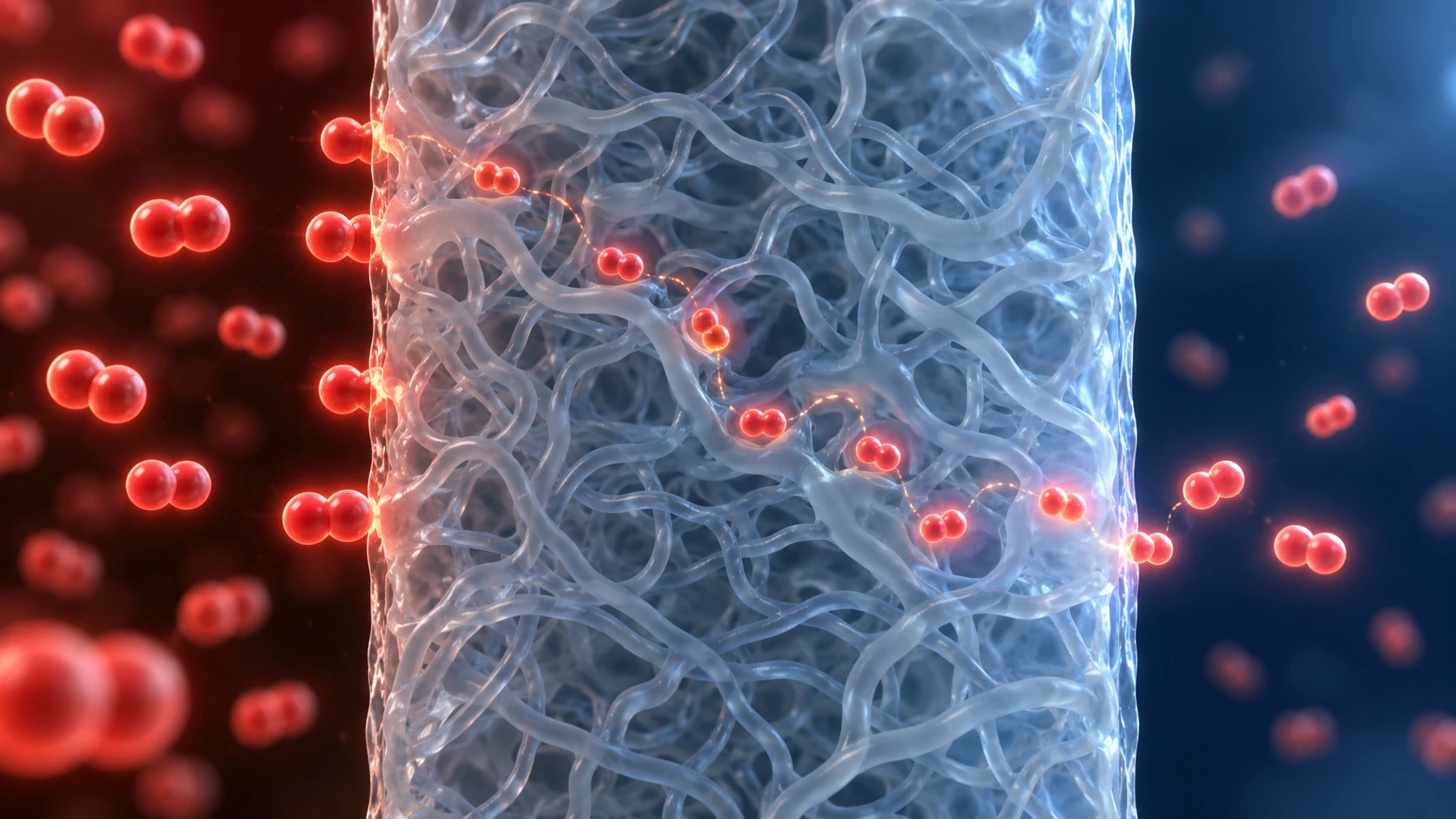
ImageGen conceptual illustration (not a real photograph or measurement). See the original diagram for exact values, names and structure.
Show original diagram with exact annotations and values
The review by Wijmans and Baker (Journal of Membrane Science, 1995) frames transport through a membrane as a solution-diffusion model: each component dissolves into the membrane and then diffuses through it down a chemical-potential gradientSourced. That is the starting point for thinking about gas permeation through polymer film. From it, a materials engineer can draw several practical readings (the points below are our commentary).
- The permeability coefficient is the product of "how easily it dissolves" and "how easily it moves": P = D × S. A gas that dissolves poorly (small S), or a film in which molecules move slowly (small D), gives low permeation
- Inversely proportional to thickness: for the same material, doubling the thickness roughly halves the amount that passes, provided the film is homogeneous and at steady state. Films with defects, and multilayer films, depart from this simple relation
- Strongly temperature dependent: Carcia et al. measured a 25 nm Al2O3 film made by ALD (atomic layer deposition) with the calcium corrosion test (Ca test). The water vapour transmission rate (WVTR) was 1.7×10⁻⁵ g/m²/day at 38 °C and 6.5×10⁻⁵ g/m²/day at 60 °C, and from the apparent activation energy the value at 23 °C was estimated at 6×10⁻⁶ g/m²/daySourced. A rise of 22 °C, from 38 to 60 °C, is about 3.8 timesOur calculation (6.5 / 1.7 = 3.82)
- Water itself changes the film: in hydrophilic polymers, the water absorbed changes how freely the chains move. EVOH in Section 5 is the classic case
If you work with metals or ceramics, P = D × S will be familiar as the equation for diffusion and solid solution in a solid. What differs in polymers is that chain mobility changes sharply above or below the glass transition temperature (Tg), and that the permeating species (water above all) plasticises the polymer and changes D itself (our commentary). Tg itself is covered in our explainer on glass transition and creep. The dry Tg of EVOH, which we look at later (50 to 63 °C in Kuraray's stated values), sits close to room temperatureSourced. In other words, EVOH used at room temperature is being used close to its Tg while it absorbs water, so it is only natural that humidity moves its performance.
3. Measurement standards — the same "permeability" can mean different methods and conditions
Permeability standards divide by what is measured (oxygen or water vapour), how the permeation is driven (pressure difference or concentration difference), and what detects it (pressure sensor, coulometry, infrared, mass and so on). The table lists those whose number and title we could confirm on the standards bodies' official pages. The standards themselves are paid documents, so we limit ourselves to the stated scope and method, and do not cover measurement ranges or precision figures.
| Standard | Measures | Method / detection | As stated on the official page |
|---|---|---|---|
| ISO 15105-2:2025 | Gas transmission rate | Equal-pressure method | Applies to all plastic materials, including film, sheet, laminates, co-extruded materials and flexible plastic-coated materials. The second edition (November 2025) replaces the 2003 edition |
| ISO 15106-3:2003 | Water vapour transmission rate | Electrolytic detection sensor method | An instrumental method that finds the water vapour transmission rate of plastic film and sheet, and of multilayer structures containing plastic, with an electrolytic detection sensor |
| ASTM D3985 | Oxygen transmission rate | Coulometric sensor | Determines oxygen transmission rate at steady state for film, sheet, laminates, co-extrusions and plastic-coated paper or fabric. In its scope statement, the range over which the standard's statistics show the measurement to be valid is 0.063 to 64.4 cc/(m²·day) |
| ASTM F1249 | Water vapour transmission rate | Modulated infrared sensor | Covers single-layer and multilayer polymers and foils up to 3 mm thick (including coated materials). Validity shown by interlaboratory testing for 0.052 to 26 g/(m²·day). A note cautions that the relationship in which WVTR is inversely proportional to thickness and proportional to the water vapour partial pressure difference does not always hold, and urges care in handling permeance and permeability coefficient |
| ASTM E96/E96M | Water vapour transmission | Gravimetric (desiccant and water methods) | Titled as gravimetric determination of water vapour transmission of materials. Covers paper, plastic film, sheet materials, coatings, foams, fibreboard, plaster products and others. Test conditions are at the user's discretion and must always be reported with the result |
| JIS K 7126-1:2006 | Gas transmission rate | Differential-pressure method (annexes: pressure sensor method, gas chromatograph method) | "Plastics — Film and sheeting — Test method for gas transmission rate — Part 1: Differential-pressure method" (title translated from Japanese). Based on ISO 15105-1:2002 |
| JIS K 7129:2008 | Water vapour transmission rate | Instrumental methods (Annex A: humidity sensor method; Annex B: infrared sensor method; others) | "Plastics — Film and sheeting — Determination of water vapour transmission rate (instrumental method)" (title translated from Japanese) |
All Sourced (ISO 15105-2 [Reference 1], ISO 15106-3 [Reference 2], ASTM D3985 [Reference 3], ASTM F1249 [Reference 4], ASTM E96/E96M [Reference 5], the public preview of JIS K 7126-1 [Reference 6], the public preview of JIS K 7129 [Reference 7]). These are titles and scope statements confirmed on the standards bodies' official pages and public previews; we have not checked the body of any standard (measurement ranges, precision, numerical conditions).
A units trap that is easy to miss
Kuraray gives the oxygen transmission rate of EVAL™ in the unit "cm³·20 µm/m²·day·atm" (the company page prints the area part as "m³", but because the quantity is a rate per unit area we read it here as m²)Sourced. This means "the volume (cm³) of oxygen passing through a 20 µm film, per square metre, per day, per 1 atm of oxygen pressure difference" (our commentary). It includes the film thickness, so a different thickness needs a conversion. By contrast, the "transmission rate" in the standards (GTR or WVTR) is the value for that test specimen itself, and the "permeability coefficient" is the value with thickness removed. So even when the word is the same, you have to tell whether it is the specimen's own value, a value normalised to a common thickness, or a material constant.
4. A materials engineer's view (1): a number only means something together with its conditions
When you compare barrier numbers, they are not comparable unless these five things are aligned (our commentary).
- Substance: oxygen or water vapour? EVOH is prized as an oxygen barrier but its transmission rate moves with humidity, whereas PVDC, which we look at later, is described by Asahi Kasei as a high barrier to both oxygen and water vapour
- Temperature and relative humidity: the oxygen transmission rates in Kuraray's EVAL™ table are for 20 °C, 65% RH, ISO 14663-2 Annex CSourced. They cannot be placed beside values at another humidity
- Thickness: normalised to 20 µm, or the actual thickness?
- Measurement method: differential-pressure, equal-pressure and gravimetric methods detect different things and impose different conditions on the specimen. The scope of ASTM E96 states that test conditions are at the user's discretion but must always be reported with the resultSourced
- Specimen: single layer or multilayer, and which side the coating faces. For multilayer and coated materials, the same nominal value can change with history (bending, heat, water)
In materials development, a mismatch between your own measurement conditions and the customer's conditions of use shows up as variation in performance. Even if you are not a polymer specialist, the habit from metals and ceramics of "matching atmosphere and temperature" carries over unchanged.
5. The materials that provide the barrier — EVOH, PVDC, inorganic deposition, multilayer films
The review by Lange and Wyser (Packaging Technology and Science, 2003) sorts innovation in barrier technology for plastic packaging into five directions: (a) thin transparent vacuum-deposited coatings, (b) new barrier polymers used as discrete layers, (c) blends of barrier polymers with commodity polymers, (d) organic barrier coatings, and (e) nanocompositesSourced. The review also notes that the existing barrier solutions each have their own drawbacks, such as cost, sensitivity to water, opacity and environmental imageSourced. Here we look at the materials among them that come up most often in real packaging and electronic materials.
(1) EVOH — the standard oxygen barrier, but sensitive to humidity
EVOH is a copolymer of ethylene and vinyl alcohol, and Kuraray's EVAL™ is the best-known product. The company lists as a feature an excellent barrier to the permeation of gases including oxygenSourced. The table sets out the stated values of its standard grades in order of ethylene content.
| Grade (manufacturer's stated) | Ethylene content | Melting point | Glass transition (dry) | Oxygen transmission rate (20 °C, 65% RH) |
|---|---|---|---|---|
| L171B | 27 mol% | 190 °C | 63 °C | 0.1 |
| F101B | 32 mol% | 183 °C | 60 °C | 0.3 |
| H171B | 38 mol% | 172 °C | 56 °C | 0.7 |
| E105B | 44 mol% | 165 °C | 53 °C | 1.9 |
| G156B | 48 mol% | 157 °C | 50 °C | 3.7 |
All Sourced (Kuraray EVAL™ product page [Reference 8]; manufacturer's stated values). The unit of oxygen transmission rate is cm³·20 µm/m²·day·atm (20 °C, 65% RH, ISO 14663-2 Annex C; the page prints the area part as "m³"). Glass transition is under "Dry" conditions. The page does not describe how melting point and Tg were measured, and we have not checked this. The table puts standard grades from one manufacturer under the same conditions to show the effect of ethylene content; it does not rank products.
From the table, raising the ethylene content from 27 mol% to 48 mol% takes the oxygen transmission rate from 0.1 to 3.7, about 37 timesOur calculation (3.7 / 0.1 = 37). A likely background is the difference in molecular structure: the ethylene portion is hydrophobic, while the hydroxyl groups of the vinyl alcohol portion readily form hydrogen bonds (our commentary. The Kuraray page does not give this hydrogen-bonding explanation; it is our inference). Melting point and Tg, on the other hand, line up in the direction of falling as ethylene content risesSourced. You gain processability and lose oxygen barrier. That is the trade-off in grade selection (our commentary).
And this table gives values at a single point, 20 °C and 65% RH. The study by Zhang et al. (Journal of Applied Polymer Science, 2001) examined oxygen and water vapour permeation through EVOH film as a function of temperature and relative humidity, and showed that permeation is lowest at low humidity and rises sharply above 75% relative humidity, and that it also depends on ethylene content and on stretching (orientation)Sourced. The authors attribute the low permeation at low humidity to the restricted chain motion caused by strong interaction between water molecules and the polymerSourced.
Left exposed to the outside air on its own, EVOH loses performance where humidity is high. For that reason EVOH is generally used as a multilayer structure sandwiched on both sides by polyolefins or other moisture-resistant layers (our commentary; Fig. 3). In other words, the performance of a "barrier material" is the result of a design that includes not just the material but the humidity environment the layer structure creates. By analogy with surface treatment or cladding of metals, the idea is to isolate the base material's weakness (water) with another layer so that its strength can be used. Adhesive resins are used to bond the layers. The basics of thermoplastics and thermosets are left to our explainer on thermoplastics and thermosets.
(2) PVDC — a coating polymer that aims at both oxygen and water vapour
PVDC (polyvinylidene chloride) is a polymer of vinylidene chloride that contains two chlorine atoms per monomer unit, and an explainer in Plastics Engineering (SPE) describes it as having excellent barrier to gases and liquids, chemical resistance and flame retardancySourced. For its water-borne PVDC emulsion (PVDC latex), Asahi Kasei says it forms a thin film with high barrier to gases such as oxygen and to water vapour, with good heat-sealing and high-frequency-sealing properties as well. The uses given are coating films of OPP (oriented polypropylene), PET, nylon and PVCSourced.
What deserves attention here is that PVDC is supplied as a latex dispersed in water and applied to the film as a coating (our summary). Polymers with high barrier tend to resist dissolving in solvents because of crystallinity and hydrogen bonding (commentary), and the form in which a polymer can be applied (solvent, water or solvent-free) sets the coating technology you can choose. We take this up in Section 9. The chlorine content can become an issue in incineration and recycling (commentary; we have not checked specific figures or regulations in primary sources).
(3) Inorganic vapour deposition and ALD — an ultrathin, nearly impermeable film
In this approach, an inorganic film such as silicon oxide or aluminium oxide is laid down thinly on a polymer film by a vacuum process. Lange and Wyser list thin transparent vacuum-deposited coatings as one of their five directionsSourced.
In an example of an Al2O3 film made by ALD (atomic layer deposition), Carcia et al. formed a 25 nm Al2O3 film on plastic and measured WVTR with the Ca test. The result was 1.7×10⁻⁵ g/m²/day at 38 °C, very close to the value for a glass control sampleSourced. What matters here is that a level of 10-5 g/m²/day is more than three orders of magnitude below the lower end of the range over which ASTM F1249 (Section 3) shows measurement to be valid (0.052 g/m²/day). 0.052 / 1.7×10⁻⁵ is about 3,100 timesOur calculation. To measure permeation at this level, Carcia et al. used the Ca test, which exploits the way a calcium film changes when it reacts with waterSourced.
(4) Multilayer films — combining layers to cover each other's weaknesses
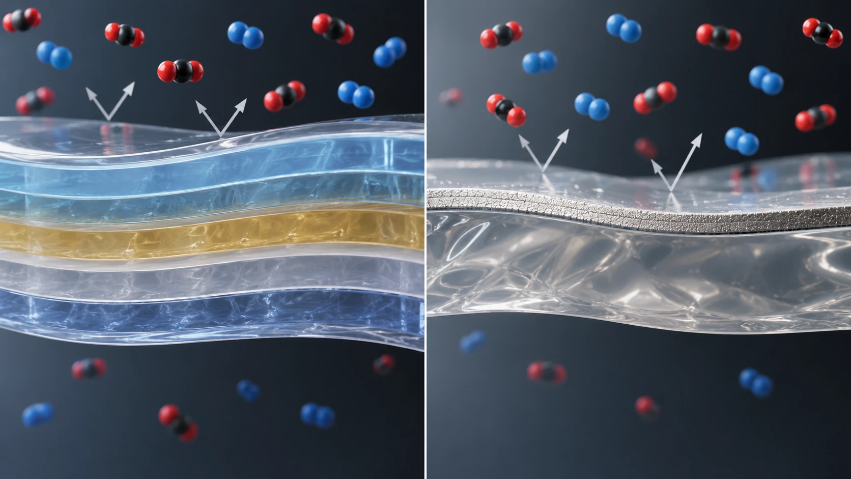
ImageGen conceptual illustration (not a real photograph or measurement). See the original diagram for exact values, names and structure.
Show original diagram with exact annotations and values
A structure that sandwiches a barrier layer between other layers, as on the left of Fig. 3, is made by co-extrusion (extruding several resins at the same time into a single film). A structure that stacks coating and deposition on a base, as on the right, is processed while a long web of film runs through the line (our commentary). What the two have in common is that they do not leave everything to a single material but give each layer its own job. The same thinking runs through the blends and composites in our explainer on polymer blends and fillers, and through the multiphase structures in our explainer on CFRP and composite materials.
6. Our calculation: how much oxygen enters through an EVOH layer in a year
Assumptions (set by this article)Our calculation
- The EVOH layer is 20 µm thick. Assume Kuraray's stated EVAL™ value (20 °C, 65% RH) holds constant for a year (365 days)
- Assume air outside (oxygen partial pressure 0.21 atm) and an oxygen partial pressure of 0 atm inside. Take the barrier layer area as 0.1 m² (both faces of the pouch together)
- Ignore the other layers (polyolefin and so on) and ingress through seals and folds
- Take the oxygen in 1 L of air as 0.21 L = 210 cm³
| Grade | Oxygen transmission rate (stated) | Oxygen entering in one year | Share of the oxygen in 1 L of air |
|---|---|---|---|
| L171B (27 mol%) | 0.1 | about 0.77 cm³ | about 0.4% |
| F101B (32 mol%) | 0.3 | about 2.3 cm³ | about 1.1% |
| G156B (48 mol%) | 3.7 | about 28 cm³ | about 13.5% |
The formula is "transmission rate × oxygen partial pressure difference × area × days" (for example 0.3 × 0.21 × 0.1 × 365 = 2.30 cm³). The purpose of this calculation is to give a feel for the fact that doubling the EVOH layer thickness roughly halves the oxygen that gets in (for a homogeneous layer at steady state), and that differences between grades count in orders of magnitude.
Assumptions and limits: in reality there are further effects: transmission rate rising sharply in environments above 75% humidity (Zhang et al.), ingress through seals, creases in the film and pinholes, and moisture migrating from the contents. How much oxygen ingress degrades the contents differs by application, and we did not confirm primary sources that give an allowable amount. The figures are not design values.
7. Defects decide permeation — inorganic thin-film barriers
An inorganic thin film itself lets almost no gas through. Even so, an inorganic thin film made on a polymer film can show a transmission rate far above the value you would expect from the properties of the inorganic material. The study by da Silva Sobrinho et al. (Journal of Vacuum Science & Technology A, 2000) showed the reason quantitatively.
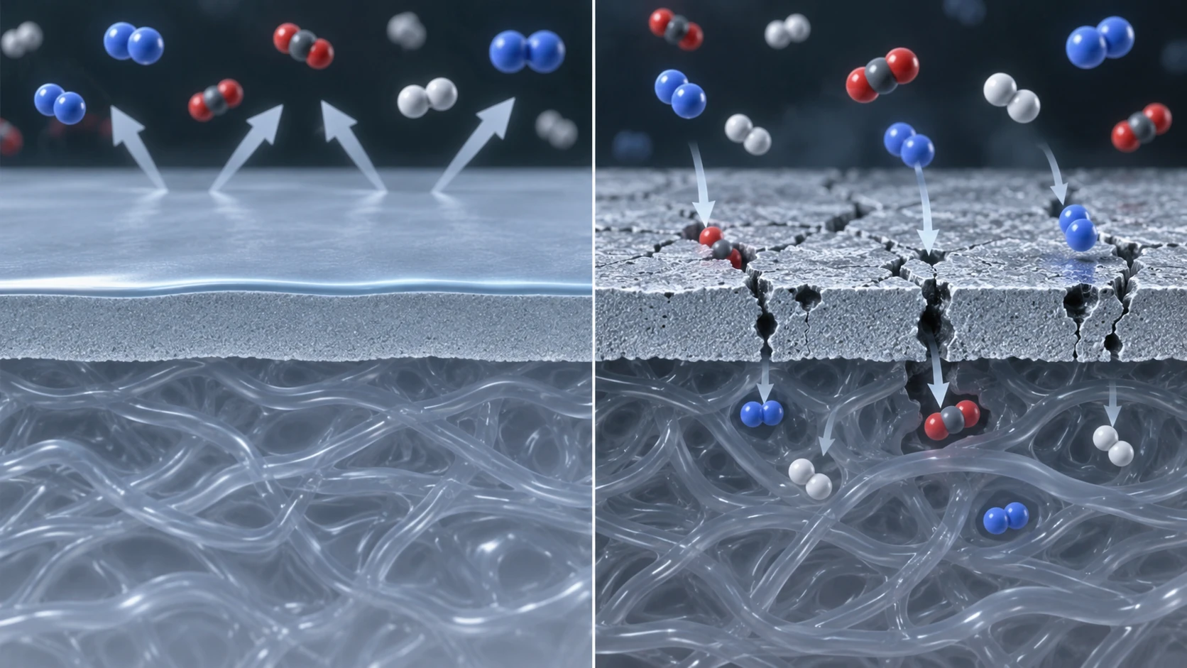
ImageGen conceptual illustration (not a real photograph or measurement). See the original diagram for exact values, names and structure.
Show original diagram with exact annotations and values
The study presents a model that describes gas permeation through the defects in a barrier coating using a simple geometric picture, and confirmed that the oxygen transmission rate (OTR) of PET film coated with SiO2 or SiN correlates with the number density and size distribution of defects. It further states that the temperature dependence of OTR (the apparent activation energy) is consistent with a model of defect-dominated transport, and that the permeation mechanisms for oxygen and for water vapour may differSourced. The study concludes that the residual oxygen transmission rate is determined by the presence of pinhole defects in the filmSourced.
AssumptionsOur calculation
- Assume the inorganic layer passes nothing at all where it is defect-free, and that permeation occurs only through defects where the polymer base film is exposed
- Take the total defect area as 0.1% of the whole (area fraction f = 0.001). Call the transmission rate of the bare base film J0
The coated transmission rate is then f × J0 = 0.001 × J0, so about 1/1000 of the base film alone serves as a guide to the lower limit. In practice gas also spreads sideways through the base around each defect before escaping, so the measured transmission rate is likely to be larger than this (our commentary).
Assumptions and limits: this calculation does not reproduce the geometric model of da Silva Sobrinho et al. We have not checked the details of that model, and the simplification that area fraction alone sets the transmission rate is our own assumption. How defect number density and size distribution actually look in real films is also outside the scope of this article's research.
8. A materials engineer's view (2): film performance is sometimes set by the holes, not the material
If the performance of an inorganic thin film is governed by defects, the focus of materials development shifts beyond how dense the inorganic material itself is to how to reduce, and how to measure, the number and size of defects. The finding that the WVTR of the 25 nm Al2O3 film grown by ALD (Carcia et al.) was close to that of the glass control can be read as an example showing that there are deposition methods that can make defects very fewSourced (the reading is our commentary).
- Effect of the substrate: roughness and foreign particles on the surface of the base film can become the starting point of defects as they are (commentary). The role of an anchor coat, as on the right of Fig. 3, is probably a layer that prepares the surface between base and inorganic layer (commentary; we have not confirmed its role in any individual product)
- Mechanical load: a hard inorganic thin film on a soft polymer is prone to cracking when the film bends or stretches, a weakness of that combination of materials (commentary; we have not confirmed numbers such as the strain at which cracking starts)
- Difficulty of evaluation: water vapour transmission in the 10-5 g/m²/day range can only be measured by special methods such as the calcium corrosion test, and sits several orders of magnitude below the standard range of the standards (0.052 to 26 g/m²/day in ASTM F1249). Our explainer on encapsulation and barrier layers (perovskite solar cells) treats the same point, where the required value is close to the limit of the instrument
For those who work on surface treatments and thin films of metals and ceramics, this will look like the same pattern as plating and anodic oxide films, where pinhole density decides corrosion protection (our commentary). For polymer films there is an extra element: the base absorbs water and its behaviour shifts.
9. Coatings — solvent-borne, water-borne and UV-cured
Coating is the technology of applying a barrier layer, adhesive layer or protective layer to the surface of a polymer film. The way the film forms, and what comes off as it does, change with the form of the liquid that is applied. Here we sort out three representative routes (the sorting is our commentary; the primary sources for each route follow).
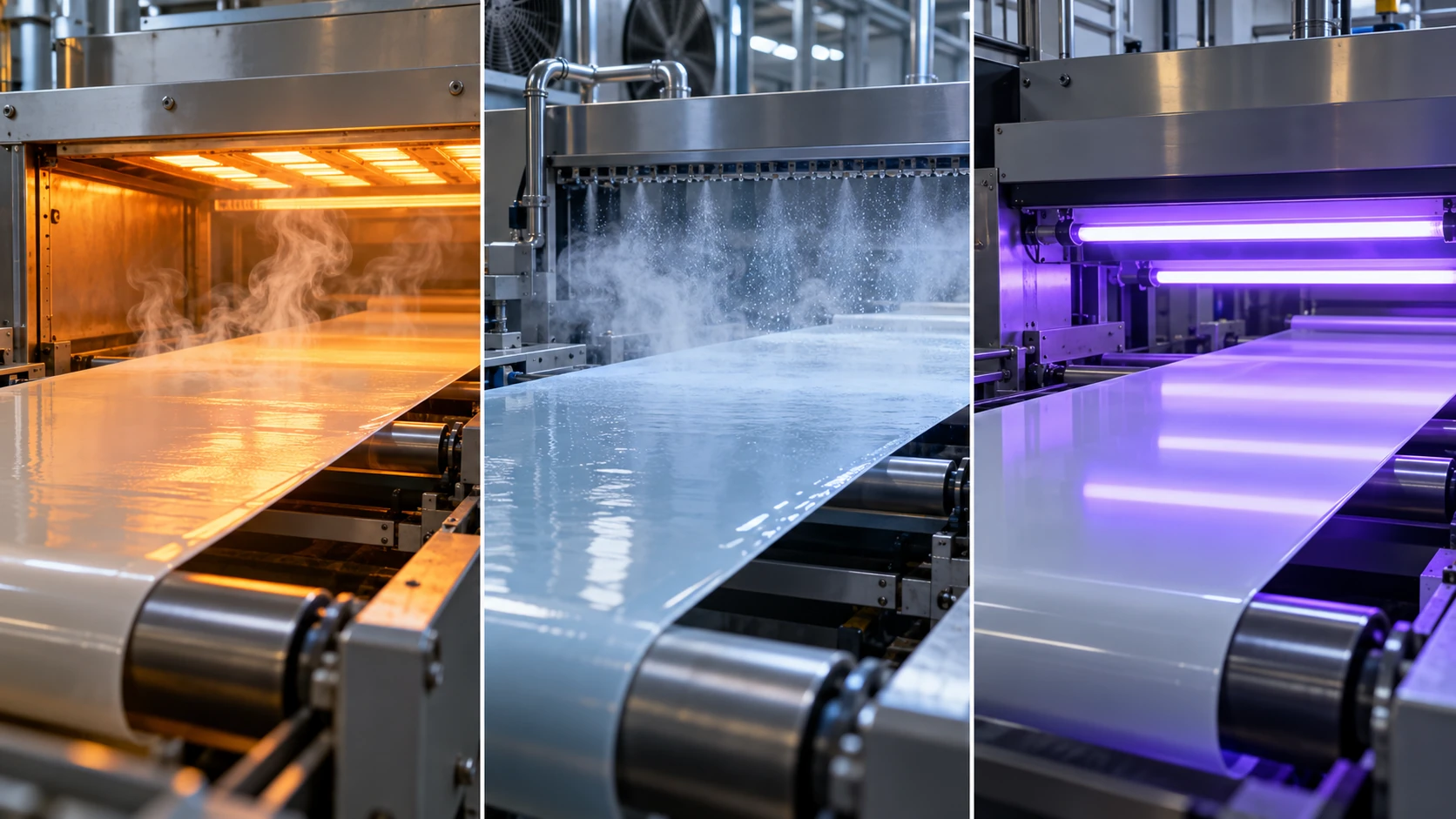
ImageGen conceptual illustration (not a real photograph or measurement). See the original diagram for exact values, names and structure.
Show original diagram with exact annotations and values
(1) Solvent-borne — it dissolves, so it can be applied; the price is solvent emission
The resin is dissolved in an organic solvent, applied, and the solvent is driven off in a drying oven to leave the film. As long as the resin's solubility fits, it is a route that makes thin, uniform coating easy (commentary). On the other hand, the solvent driven off is VOC (volatile organic compounds). The regulation discussed in Section 10 bears directly on this route.
(2) Water-borne — particles coalesce into a film
A coating liquid in which the resin is dispersed in water as particles (emulsion, latex) is applied; when the water leaves, the particles coalesce into a continuous film (commentary). The PVDC latex of Section 5 is supplied in this form and used to coat OPP, PET, nylon and PVC filmsSourced (Asahi Kasei). Water-borne systems make it easier to cut organic solvent emissions, but water evaporates slowly, so drying conditions, wetting of the substrate and the temperature at which particles coalesce into a film become design issues (our commentary; we have not checked numerical values).
(3) UV curing — light crosslinks it in an instant
Decker's review (Macromolecular Rapid Communications, 2002) surveys UV curing, in which multifunctional monomers or polymers carrying functional groups are polymerised by light into a highly crosslinked polymerSourced. For acrylate resins, it reports with real-time infrared spectroscopy (RT-IR) that curing proceeds through a long kinetic chain (7,700 mol per radical) despite a high initiation rate, and that initiation efficiency, oligomer chemical structure, light intensity and the inhibiting effect of oxygen affect the polymerisation rateSourced. The review also says that UV curing has succeeded in producing weather-resistant protective coatings in a few secondsSourced.
Seen as a materials engineer, the defining feature of UV curing is that "a highly crosslinked film forms in a short time without solvent" (our commentary). The price is that oxygen inhibition, internal stress from cure shrinkage, and light that cannot reach deep layers become design issues (oxygen inhibition is named as an influencing factor in the review above; shrinkage, stress and depth of cure are our commentary and we have not checked numbers). Shrinkage and post-cure of photocurable resins are also covered in our explainer on resins for 3D printing.
10. VOC regulation — where does the solvent go?
Regulation bears directly on the choice of coating route. Here we sort out the framework in each region, paying attention to the difference in what is regulated (emissions from installations, or content in products). Numerical limits and conditions of application are amended frequently, so this article confirms only the way each framework is built; in practice, check the latest legislation.
| Region / instrument | What it regulates | Key points confirmed |
|---|---|---|
| EU Industrial Emissions Directive 2010/75/EU (Annex VII) | Emissions from installations and activities that use organic solvents | Defines VOC as an organic compound with a vapour pressure of 0.01 kPa or more at 293.15 K, or with corresponding volatility under the particular conditions of use. Part 1 of Annex VII lists activities such as adhesive coating, coating and printing (including flexographic printing, lamination and varnishing), and Part 2 sets solvent consumption thresholds and emission limit values |
| EU Directive 2004/42/EC | VOC content in products: certain paints, varnishes and vehicle refinishing products | As the title says, it limits VOC emissions from organic solvents in certain paints and varnishes and in vehicle refinishing products. Its target differs from that of the directive above, which regulates installation emissions |
| Japan Air Pollution Control Act | Installations that emit VOC | According to the Ministry of the Environment page, the Act divides installations into nine categories and designates installations above a certain size as "VOC-emitting facilities". Curbing VOC emission and dispersion is pursued by combining regulation with voluntary action by businesses |
| U.S. EPA NESHAP (40 CFR Part 63 Subpart KK) | Hazardous air pollutants (HAP) from the printing and publishing industry | Covers publication rotogravure, product and packaging rotogravure, and wide-web flexographic printing, and requires HAP control by maximum achievable control technology (MACT). The substances covered include xylene, toluene, ethylbenzene and methyl ethyl ketone |
All Sourced (EU 2010/75/EU [Reference 17], EU 2004/42/EC [Reference 18], Ministry of the Environment [Reference 19], U.S. EPA [Reference 20]). VOC (volatile organic compounds) and HAP (hazardous air pollutants) are different in definition and in regulatory purpose, so the same group of substances may be looked at from different angles.
Part 5 of Annex VII of the Industrial Emissions Directive sets out a reduction scheme for operations using coatings, varnishes, adhesives and inks. The mass of solids used in a year (the components left as a solid after water and VOC have evaporated) is multiplied by a factor for the activity to give an "annual reference emission". That is multiplied by (the limit for residual fugitive emissions + 5)% (+15% for some categories) to give the "target emission". If actual solvent emissions are at or below the target emission, the operation complies. The factor is 4 for rotogravure and flexographic printing, for lamination and varnish coating associated with printing, for coating of textiles, film and paper, and for adhesive coating; 3 for coil coating and vehicle refinishing; 2.33 for food-contact coatings and aerospace; and 1.5 for other coatingSourced.
Assumptions (an example set by this article)Our calculation
- Annual solids use of 100 t, with a factor of 4 (the category covering lamination and varnish coating, for example)
- The fugitive emission limit is 20%, as for the category with solvent consumption above 25 t per year (the category 3 example in Part 2 of Annex VII)
Annual reference emission = 100 t × 4 = 400 t. Target emission = 400 t × (20 + 5)% = 100 t. So the target is 25% of the reference (a 75% reduction). A factor of 4 corresponds to the calculation that a solvent-borne coating of 20% solids emits solvent at four times the solids (this is our reading; the directive does not explain it that way).
An example of how to compare with a water-borne system (assumed): if the same 100 t of solids is used in a water-borne coating liquid of 40% solids with organic co-solvent at 5% of the whole liquid, the liquid is 100 / 0.4 = 250 t, of which the organic co-solvent is 250 × 0.05 = 12.5 t. This water-borne composition is a hypothetical example set by this article and is not the composition of any real product.
Assumptions and limits: real application depends on the category of installation, thresholds, whether it is new or existing, and requirements for monitoring and a solvent management plan. This calculation is meant to give a feel for how the regulatory framework thinks about the allowable solvent per unit of solids; it cannot be used to judge compliance.
11. A materials engineer's view (3): regulation becomes a constraint on material choice
Polymers with high barrier (highly crystalline, strongly hydrogen-bonded and so on) generally tend also to be hard to dissolve in solvents (our commentary). That makes the form in which the barrier layer can be supplied as a coating liquid a driver of material selection.
- Dissolves in a solvent and can be applied: solvent-borne. VOC emissions then have to be managed (recovered or treated). The EU reduction scheme states that, where lower-solvent alternatives are still under development, the implementation plan is given a period of graceSourced
- Can be dispersed in water: water-borne. A barrier polymer is supplied as particles, like PVDC latex
- Cures by reaction: UV curing and the like. A highly crosslinked film results, but as a material it comes down to designing the monomers and oligomers
- Not coated but stacked as a layer: co-extruded multilayer (left of Fig. 3). This avoids the solvent problem of coating altogether
If you read regulation as divided into "the amount that leaves the installation" (the EU Industrial Emissions Directive, Japan's Air Pollution Control Act) and "the amount contained in the product" (EU 2004/42/EC), it becomes clear which side affects your own company. Even for the same solvent, which law limits which quantity, in which unit, differs (our commentary). Note that the fact that PVDC is supplied as a water-borne emulsion and the existence of VOC regulation are matters we confirmed separately, and we do not claim a causal link between the two.
12. What is still hard, and what we could not confirm
(1) We do not cover the measurement range or precision in the standards' texts
The ISO and JIS standards are paid documents or available only as public previews, and this article stopped at confirming titles, scope and method. We have not checked the measurable range or reproducibility of ISO 15105-2 or ISO 15106-3. For ASTM D3985 and F1249 we quoted the interlaboratory validity ranges stated on the official pages (0.063 to 64.4 cc/(m²·day) and 0.052 to 26 g/(m²·day)).
(2) We do not give a table of permeability coefficients by material
We could not confirm, within the scope of this research, primary sources that let the permeability coefficients of polyethylene, PET, nylon and others be compared under matched conditions (with test method, temperature, humidity and thickness). For that reason we give no numbers other than EVOH (Kuraray's stated values) and ALD Al2O3 film (Carcia et al.). We avoid lining up values under different conditions to rank materials.
(3) Strain at which inorganic thin films crack, and the recyclability of PVDC and EVOH, are unconfirmed
We have not confirmed in primary sources the strain at which an inorganic thin film on a flexible base starts to crack, or the degree to which multilayer films containing PVDC or EVOH cause problems in recycling processes. The recycling viewpoint is covered in our explainer on plastic recycling.
(4) We give no quantitative comparison of water-borne and UV-cured routes
We could not confirm, within the scope of this research, primary sources that compare drying energy, film thickness, cure shrinkage, production speed and so on across routes under the same conditions. The sorting in Section 9 is qualitative commentary only.
(5) We have not checked the latest amendments to the regulations
Section 10 covers only the framework of each instrument and what could be read from the official pages at the time of our research. For whether there have been amendments, the dates of entry into force in each country and individual emission standards, please check the latest legislation. We have not used market-size estimates from research firms.
- Permeation is a process of "dissolving, diffusing and emerging on the other side", and the permeability coefficient can be organised as the product of the diffusion coefficient and the solubility coefficient (our commentary)
- A transmission-rate figure goes together with the substance, temperature, humidity, thickness and measurement method. The transmission rate of EVOH rises sharply above 75% relative humiditySourced
- The oxygen transmission rate of Kuraray's EVAL™ spans about 37 times, from 0.1 at 27 mol% ethylene to 3.7 at 48 mol%Our calculation
- The residual transmission rate of an inorganic thin film is sometimes governed by defects in the film rather than the materialSourced
- Coatings can be sorted into solvent-borne, water-borne and UV-cured, and solvent-borne is directly affected by VOC regulation. Regulations differ in target: emissions from installations versus content in productsSourced
13. Glossary
- Transmission rate (GTR / WVTR)
- The amount of gas (water vapour) passing through a test specimen per unit area and unit time. Always stated together with its conditions.
- Permeability coefficient
- How readily a material lets a substance through, as a material constant with thickness removed. The product of the solubility coefficient and the diffusion coefficient.
- Solution-diffusion model
- The idea that a gas dissolves into a film, diffuses down the concentration gradient and passes through.
- EVOH
- Ethylene-vinyl alcohol copolymer. Excellent oxygen barrier, but sensitive to humidity.
- PVDC
- Polyvinylidene chloride. Has barrier to oxygen and water vapour, and is applied to films as a latex.
- Co-extrusion
- A process that extrudes several resins at the same time to make a single multilayer film.
- ALD
- Atomic layer deposition. A film-growth method that builds up a film one atomic layer at a time and readily makes thin films with few pinholes.
- Ca test
- A method that uses the way a calcium film changes when it reacts with water to measure extremely small water vapour transmission.
- Pinhole
- A tiny hole in a film. It becomes an entrance for permeation through a barrier film.
- VOC
- Volatile organic compound. In the EU Industrial Emissions Directive, defined as having a vapour pressure of 0.01 kPa or more at 293.15 K, among other conditions.
- HAP
- Hazardous air pollutant. The subject of regulation under the U.S. EPA's NESHAP.
- UV curing
- A curing method in which ultraviolet light generates active species from a photoinitiator, polymerising and crosslinking monomers.
- Solids content
- The part of a coating liquid that remains as the film after water or solvent has evaporated.
14. References (primary sources)
- ISO ISO 15105-2:2025 Plastics film and sheeting — Determination of gas-transmission rate — Part 2: Equal-pressure method — iso.org
- ISO ISO 15106-3:2003 Plastics — Film and sheeting — Determination of water vapour transmission rate — Part 3: Electrolytic detection sensor method — iso.org
- ASTM International ASTM D3985-24 Standard Test Method for Oxygen Gas Transmission Rate Through Plastic Film and Sheeting Using a Coulometric Sensor — store.astm.org
- ASTM International ASTM F1249-25 Standard Test Method for Water Vapor Transmission Rate Through Plastic Film and Sheeting Using a Modulated Infrared Sensor — store.astm.org
- ASTM International ASTM E96/E96M-24 Standard Test Methods for Gravimetric Determination of Water Vapor Transmission Rate of Materials — store.astm.org
- Japanese Standards Association (JSA) JIS K 7126-1:2006 Plastics — Film and sheeting — Gas transmission rate test method — Part 1: Differential-pressure method (public preview PDF, in Japanese; title translated) — webdesk.jsa.or.jp
- Japanese Standards Association (JSA) JIS K 7129:2008 Plastics — Film and sheeting — Determination of water vapour transmission rate (instrumental method) (public preview PDF, in Japanese; title translated) — webdesk.jsa.or.jp
- Kuraray EVAL™ product page (ethylene content, melting point, glass transition and oxygen transmission rate by grade) — kuraray.com
- Zhang et al. Permeation of oxygen and water vapor through EVOH films as influenced by relative humidity, J. Appl. Polym. Sci. 82, 1866–1872 (2001) — doi.org/10.1002/app.2030
- Asahi Kasei PVDC latex (Portal for Medical Materials) — asahi-kasei.co.jp
- Plastics Engineering (SPE) Inside Materials – PVDC (October 2024) — plasticsengineering.org
- Lange and Wyser Recent innovations in barrier technologies for plastic packaging — a review, Packag. Technol. Sci. 16, 149–158 (2003) — doi.org/10.1002/pts.621
- da Silva Sobrinho et al. Defect-permeation correlation for ultrathin transparent barrier coatings on polymers, J. Vac. Sci. Technol. A 18, 149–157 (2000) — doi.org/10.1116/1.582156
- Carcia et al. Ca test of Al2O3 gas diffusion barriers grown by atomic layer deposition on polymers, Appl. Phys. Lett. 89, 031915 (2006) — doi.org/10.1063/1.2221912
- Wijmans and Baker The solution-diffusion model: a review, J. Membr. Sci. 107, 1–21 (1995) — doi.org/10.1016/0376-7388(95)00102-I
- Decker Kinetic Study and New Applications of UV Radiation Curing, Macromol. Rapid Commun. 23, 1067–1093 (2002) — doi.org/10.1002/marc.200290014
- European Union Directive 2010/75/EU on industrial emissions (Annex VII, Chapter V), EUR-Lex — eur-lex.europa.eu
- European Union Directive 2004/42/EC (decorative paints and vehicle refinishing products), EUR-Lex — eur-lex.europa.eu
- Ministry of the Environment, Japan Controlling emissions of volatile organic compounds (VOC) (in Japanese) — env.go.jp
- U.S. Environmental Protection Agency (EPA) The Printing and Publishing Industry: NESHAP — epa.gov
15. Claim-to-source audit
| Claim in the text | Basis | Label |
|---|---|---|
| That ISO 15105-2:2025 defines the equal-pressure method for gas transmission rate of film, sheet, laminates, co-extruded materials and flexible plastic-coated materials, and that the second edition (November 2025) replaces the 2003 edition | ISO official page[Reference 1] https://www.iso.org/standard/91001.html | Sourced |
| The title of ISO 15106-3:2003 (water vapour transmission rate by the electrolytic detection sensor method) | ISO official page[Reference 2] https://www.iso.org/standard/29783.html | Sourced |
| The scope of ASTM D3985 (oxygen transmission rate of film, sheet, laminates, co-extrusions and plastic-coated paper or fabric; coulometric sensor) and the validated range of 0.063 to 64.4 cc/(m²·day) | ASTM official page (D3985-24)[Reference 3] https://store.astm.org/d3985-24.html | Sourced |
| The scope of ASTM F1249 (up to 3 mm thick; modulated infrared sensor), the validated range of 0.052 to 26 g/(m²·day), and the note that the relationship of transmission rate to thickness and partial pressure difference does not always hold | ASTM official page (F1249-25)[Reference 4] https://store.astm.org/f1249-25.html | Sourced |
| The title of ASTM E96/E96M, its two methods (desiccant and water), and that test conditions are at the user's discretion and reported with the result | ASTM official page (E96/E96M-24)[Reference 5] https://store.astm.org/e0096_e0096m-24.html | Sourced |
| The title of JIS K 7126-1:2006 (differential-pressure method), its annexes (pressure sensor method, gas chromatograph method), and that it is based on ISO 15105-1:2002 | JSA public preview[Reference 6] https://webdesk.jsa.or.jp/preview/pre_jis_k_07126_001_000_2006_j_ed10_ch.pdf | Sourced |
| The title of JIS K 7129:2008 (instrumental method) and the structure of Annex A (humidity sensor method) and Annex B (infrared sensor method) | JSA public preview[Reference 7] https://webdesk.jsa.or.jp/preview/pre_jis_k_07129_000_000_2008_j_ed11_ch.pdf | Sourced |
| For the five standard EVAL™ grades: ethylene content (27 to 48 mol%), melting point (190 to 157 °C), glass transition (dry, 63 to 50 °C) and oxygen transmission rate (0.1 to 3.7; 20 °C, 65% RH, ISO 14663-2 Annex C). The statement of an excellent barrier to the permeation of gases including oxygen. That the unit is printed with m³ | Kuraray EVAL™ product page (manufacturer's stated values)[Reference 8] https://www.kuraray.com/in-en/products/eval/ | Sourced |
| That the oxygen and water vapour transmission rates of EVOH film change markedly with temperature and relative humidity, are lowest at low humidity and rise sharply above 75% relative humidity, depend on ethylene content and orientation, and that the low rate at low humidity is attributed to restricted chain motion from strong interaction with water molecules | Abstract of Zhang et al. (2001)[Reference 9] https://doi.org/10.1002/app.2030 | Sourced |
| That PVDC latex forms a thin film with high barrier to oxygen and other gases and to water vapour, and is used to coat OPP, PET, nylon and PVC films | Asahi Kasei product page[Reference 10] https://www.asahi-kasei.co.jp/fibers/en/medical/products/latex.html | Sourced |
| That PVDC is a polymer of vinylidene chloride containing two chlorine atoms per monomer unit, and has excellent barrier, chemical resistance and flame retardancy | Plastics Engineering (SPE) explainer[Reference 11] https://plasticsengineering.org/2024/10/inside-materials-pvdc-006906 | Sourced |
| That innovation in barrier technology for plastic packaging is sorted into five directions (vacuum-deposited coatings, barrier polymers, blends, organic barrier coatings, nanocomposites), and that existing solutions have drawbacks in cost, sensitivity to water, opacity and environmental image | Abstract of Lange and Wyser (2003)[Reference 12] https://doi.org/10.1002/pts.621 | Sourced |
| That for PET coated with SiO2 and SiN, defect number density and size correlate with oxygen transmission rate, that the residual oxygen transmission rate is governed by defects, and that the permeation mechanisms for oxygen and water vapour may differ | Abstract of da Silva Sobrinho et al. (2000)[Reference 13] https://doi.org/10.1116/1.582156 | Sourced |
| That the WVTR of a 25 nm Al2O3 ALD film is 1.7×10⁻⁵ g/m²/day at 38 °C and 6.5×10⁻⁵ g/m²/day at 60 °C, that the estimate at 23 °C is 6×10⁻⁶ g/m²/day, that it is close to the glass control, and that it was measured by the Ca test | Abstract of Carcia et al. (2006)[Reference 14] https://doi.org/10.1063/1.2221912 | Sourced |
| That transport through a membrane is organised as a solution-diffusion model in which each component dissolves into the membrane and diffuses through it down a chemical-potential gradient | Review by Wijmans and Baker (1995) (the title and content widely known in the field; we did not recheck the details of the full text)[Reference 15] https://doi.org/10.1016/0376-7388(95)00102-I | Sourced |
| That UV curing is highly crosslinked photopolymerisation of multifunctional monomers, that acrylate systems have a long kinetic chain (7,700 mol per radical), that oxygen inhibition and other factors affect the polymerisation rate, and that there are successes in making protective coatings in a few seconds | Abstract of Decker (2002)[Reference 16] https://doi.org/10.1002/marc.200290014 | Sourced |
| The definition of VOC in the EU Industrial Emissions Directive (vapour pressure of 0.01 kPa or more at 293.15 K), the list of activities and thresholds in Annex VII, the reduction scheme in Part 5 (solids × factor; target emission = reference emission × (fugitive limit + 5)%; grace where lower-solvent alternatives are under development), and the factor values | EUR-Lex, Directive 2010/75/EU[Reference 17] https://eur-lex.europa.eu/legal-content/EN/TXT/?uri=CELEX:32010L0075 | Sourced |
| That Directive 2004/42/EC limits VOC emissions from organic solvents in certain paints, varnishes and vehicle refinishing products | EUR-Lex, Directive 2004/42/EC (title)[Reference 18] https://eur-lex.europa.eu/legal-content/EN/TXT/?uri=CELEX:32004L0042 | Sourced |
| That Japan's Air Pollution Control Act divides installations into nine categories and designates installations above a certain size as VOC-emitting facilities, and that it proceeds by combining regulation with voluntary action | Ministry of the Environment page[Reference 19] https://www.env.go.jp/air/osen/voc/voc.html | Sourced |
| That the U.S. EPA's NESHAP (40 CFR Part 63 Subpart KK) regulates HAP from publication and product-and-packaging rotogravure and wide-web flexographic printing by MACT, with xylene, toluene, methyl ethyl ketone and others among the substances covered | U.S. EPA page[Reference 20] https://www.epa.gov/stationary-sources-air-pollution/printing-and-publishing-industry-national-emission-standards | Sourced |
| A rise of about 3.8 times in WVTR from 38 to 60 °C; a ratio of about 37 times between the oxygen transmission rates at 27 mol% and 48 mol%; a ratio of about 3,100 times between the lower end of the validated range of ASTM F1249 and the WVTR of the Al2O3 film | Our calculation. Divisions of published values from Carcia et al. [Reference 14], Kuraray [Reference 8] and ASTM F1249 [Reference 4]; because measurement conditions differ from value to value, these are not like-for-like comparisons | Our calculation |
| Oxygen entering through a 20 µm EVOH layer in a year (about 0.77 / 2.3 / 28 cm³), a guide to the lower limit of transmission rate at a defect area fraction of 0.1% (about 1/1000 of the base), the numerical example of the EU reduction scheme (reference emission 400 t, target 100 t, 75% reduction) and the hypothetical water-borne composition (12.5 t) | Our calculation. Layer thickness, area, oxygen partial pressure, defect area fraction, solids use and water-borne composition are all assumptions set by this article. They do not show an allowable amount of oxygen ingress or the composition of any real product | Our calculation |
| The framing P = D × S; the reading that permeation is inversely proportional to thickness; plasticisation by water; the contrast with diffusion in metals and ceramics; that EVOH is used sandwiched in multilayers; the hydrogen-bonding explanation; the point about chlorine in PVDC; the role of the anchor coat; the tendency of inorganic thin films to crack; the design issues of water-borne and UV-cured routes; and reading regulation as divided into "emissions from installations" and "content in products" | This article's organisation and commentary based on published content. Not views expressed by any company or agency | Commentary |
| Measurement range and precision in the standards' texts, a table of permeability coefficients by material, the strain at which inorganic thin films crack, the recyclability of multilayer films, a quantitative comparison of water-borne and UV-cured routes, and the latest amendments to regulations | Not stated, because they could not be confirmed in published primary sources within the scope of this article | Commentary |
| That Figs. 1 to 5 are explanatory drawings rather than real observations or design drawings, and that the hero image and Fig. 6 are AI-generated images | Our note | Commentary |
Last updated 2 October 2026. Sources are limited to primary material (official pages and public previews of standards bodies, peer-reviewed papers, official product pages of manufacturers, and published material from public bodies in the EU, Japan and the United States). Because the article includes structural readings and materials-design interpretations, those are marked as Commentary and kept separate from sourced fact. Measurement range and precision in the standards' texts, a table of permeability coefficients by material, the strain at which inorganic thin films crack, the recyclability of multilayer films, a quantitative comparison of water-borne and UV-cured routes, and the latest amendments to regulations are not stated here because they could not be confirmed in published primary sources. Catalogue values are manufacturers' stated values, and values for different grades and conditions are not lined up to rank them. All figures are explanatory concept graphics. Figs. 1 to 5 are vector drawings; the hero image and Fig. 6 are AI-generated images, and none of them shows a real product, equipment or micrograph.