TECHNOLOGY EXPLAINER
Heat Sinks
— Sometimes the Performance Is Set by the Joint, Not by the Shape of the Fins
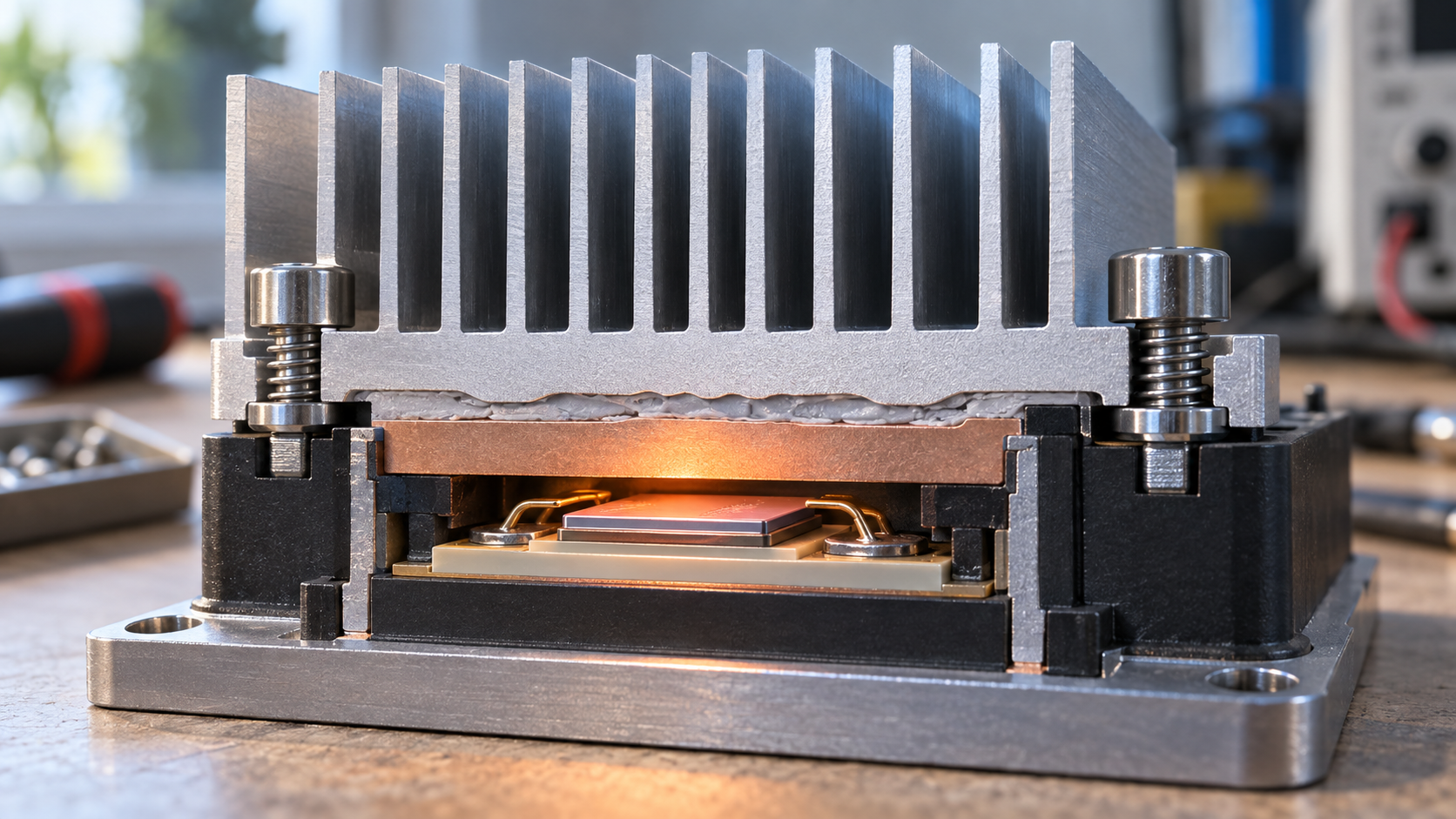
A heat sink is a metal radiator that passes a component's heat to the air. The fins that widen the surface area catch the eye, but thermal resistance adds up in series from chip to air, so the quality of the TIM (thermal interface material), the bonding and the fastening sets how big the heat sink has to be. This article sorts out how heat moves, materials, manufacturing processes, and natural versus forced air cooling, and then puts the weight on the link with the adhesives and encapsulants field, joining, bonding and compressing the TIM, from a materials engineer's point of view.
- What a heat sink is, in three points
- Adding up thermal resistance: Rja = Rjc + Rcs + Rsa
- Our calculation: the quality of the TIM changes the temperature rise left for the heat sink
- Principles: conduction, convection, radiation and fin efficiency
- A materials engineer's view (1): materials — aluminium, copper, heat pipes, graphite and composites
- Manufacturing: extrusion, die casting, bonding, folding, forging, skiving and machining
- A materials engineer's view (2): the joint between fin and base becomes thermal resistance
- Natural and forced air cooling: the same Rsa can need ten times the volume
- Heat sinks, TIMs, bonding and fastening: designing the attachment
- A materials engineer's view (3): clamping load, and bonding as an alternative
- Reading performance: a catalogue Rsa is not one number
- Open problems, and what this article could not confirm
- Glossary / References / Claim-to-source audit
Sourced = stated in published material from technical journals, standards bodies, public institutions or manufacturers (link given)
Our calculation = a value this article derived from assumptions it states
Not yet confirmed = a plan or target with no confirmed track record
Structural readings and materials-design interpretations are marked separately as Commentary.
Catalogue values are labelled manufacturer's stated value, and this article does not rank products or companies.
1. What a heat sink is, in three points
A heat sink is a passive radiator that passes a component's heat to the air (or a liquid) from an enlarged metal surface. The technical page of ABL (a heat sink manufacturer) describes a heat sink as a part that cools by increasing the surface area in contact with the surrounding fluid, and says that attachment methods and thermal interface materials (TIMs) also affect the eventual chip temperatureSourced.
- Role: it is the last stage of the heat path from the component case to the surrounding air. Seri Lee (Electronics Cooling, 1995) points out that heat transfer across the solid-air interface is the least efficient step in the systemSourced
- What decides it: not only fin surface area. Also the thermal conductivity of the material, the shape and spacing of the fins, the air speed, and the interface between component and heat sink (TIM, bonding, fastening)
- The emphasis of this article: less the heat sink itself than how it is attached to the component: joining, bonding and compression of the TIM. Our explainers on thermal interface materials and thermal pads are the groundwork
Thermal resistance adds up, so what is lost in the TIM has to be won back by making the heat sink larger. Seri Lee gives the junction-to-ambient resistance as Rja = Rjc + Rcs + Rsa (junction to case, case to heat sink, heat sink to air)Sourced. The middle term, Rcs (the interface between case and heat sink), is, the same article says, set by surface finish, flatness, mounting pressure, contact area, and the type and thickness of the interface materialSourced.
The big picture of TIMs (TIM1 and TIM2, Rth = L/k + Rc1 + Rc2) is in our explainer on thermal interface materials, how to read the numbers for sheet-type pads is in our explainer on thermal pads, and paste-type and liquid gap fillers are in our explainer on high-thermal-conductivity pastes and gap fillers. We do not repeat them here and concentrate on the view from the heat sink's side. For the basics of thermal expansion see our explainer on the coefficient of thermal expansion, and for the chemistry of epoxy see our explainer on epoxy resins.
2. Adding up thermal resistance: Rja = Rjc + Rcs + Rsa
Seri Lee's article explains thermal resistance by analogy with electrical resistance. Thermal resistance R is the temperature difference ΔT divided by the heat flow Q (°C/W), and heat flows in series from junction to case, interface, heat sink and air, so the resistances of the stages addSourced.
- Rjc (junction to case): specified by the device manufacturer; the user cannot change it
- Rcs (case to heat sink): the interface resistance. It can be improved greatly by the quality of the surface finish and the choice of interface material
- Rsa (heat sink to air): the thermal resistance of the heat sink
- The upper limit the heat sink must meet is Rsa = (Ts − Ta)/Q − Rjc − Rcs. The ambient air temperature Ta is typically 35 to 45°C if external air is used and 50 to 60°C inside equipmentSourced
3. Our calculation: the quality of the TIM changes the temperature rise left for the heat sink
Let us check the equation with numbers. We apply the thermal impedance from the Henkel datasheet we read in the previous article (GAP PAD TGP 2000, 0.040 inch thick) to a 40 x 40 mm componentOur calculation.
Assumptions: power Q = 60 W, junction limit Tj = 100°C, ambient Ta = 40°C, Rjc = 0.2 °C/W (our assumption). Contact area = 40 x 40 mm = 16 cm² = 2.48 in². The TIM is the thermal impedance of TGP 2000 (0.97 °C·in²/W at 10% deflection and 0.80 at 30%, datasheet values).
- Rcs (10% deflection): 0.97 ÷ 2.48 = 0.39 °C/W. The total resistance allowed is 60 K ÷ 60 W = 1.0 °C/W, so Rsa = 1.0 − 0.2 − 0.39 = 0.41 °C/W.
- Rcs (30% deflection): 0.80 ÷ 2.48 = 0.32 °C/W. Rsa = 1.0 − 0.2 − 0.32 = 0.48 °C/W.
- Under the same airflow, heat sink volume is roughly inversely proportional to Rsa (the approach in section 8), so the ratio of required volumes is 0.41 ÷ 0.48 = about 0.86. The calculation says that raising the TIM compression from 10% to 30% alone lets the heat sink be about 14% smaller.
In this example, of the 60 K temperature rise, the TIM takes about 23.5 K and the heat sink about 24.5 K. The TIM uses almost as much temperature difference as the heat sinkOur calculation. The TIM is a thin layer, but to the heat flow it acts as “another component”. So in heat sink design, lowering the interface resistance (flattening the surface, securing the pressure, choosing a material that wets) is worth as much as refining the fin shape. Seri Lee likewise writes that the interface resistance can be improved greatly by the surface finish and the choice of interface materialSourced.
The Rjc, the 60 W and the temperature conditions used here are our assumptions. What we want to convey is the order-of-magnitude sense that “the TIM's resistance can rival the heat sink's”, not the design values of any particular part.
4. Principles: conduction, convection, radiation and fin efficiency
ABL's technical page names three ways heat leaves a heat sink: convection into the surrounding air, conduction through the air, and radiation. It explains that as heat travels along a fin from root to tip, the fin's temperature and its heat transfer fall toward the tipSourced.
Fin efficiency: where thermal conductivity matters in choosing a material
ABL defines fin efficiency as the heat a fin actually transfers divided by the heat it would transfer if the whole fin were at the root temperature (infinite thermal conductivity), and names it as one parameter that makes a higher-conductivity material importantSourced. As the right side of Fig. 2 shows, efficiency falls as the fin gets taller and as the convection coefficient h gets larger. Copper, with its higher conductivity, loses less efficiency than aluminium under the same conditionsOur calculation (at 30 mm height and h = 50: about 0.87 for aluminium and about 0.93 for copper).
Fin spacing also has a “just right” value. In a forced-convection plate-fin example, the Electronics Cooling article by Iyengar says that too few fins give too little surface area and too many make the thin fins inefficient, so thermal resistance has a minimum in betweenSourced. In the article's example (aluminium, 0.1 x 0.1 m base, 0.05 m fin height, 20 Pa and 0.01 m³/s), the minimum of 0.135 °C/W comes at 4 fins/cm (fin thickness 0.57 mm, gap 1.93 mm), dissipating 186 W at a 25°C temperature differenceSourced. Seri Lee likewise says the optimum spacing depends strongly on air speed and fin length, and gives a table of guide values by air speed (6.5 to 13 mm for natural convection, 2 to 3.5 mm at 5 m/s, and so on)Sourced.
Radiation: not negligible in natural convection
Shabany (Electronics Cooling, 2008) writes that radiation can be a significant portion of the total heat transfer from a heat sink, particularly in natural convectionSourced. Seri Lee says radiation can account for up to 25% of total heat dissipation in natural convection, so unless there is a hotter surface nearby, the heat sink surface should be painted or anodised to enhance radiationSourced. ABL also explains that at about 0 to 100°C radiation is small relative to convection, that emissivity matters little for finned heat sinks in natural or forced flow, but that surface colour matters where convection is low, as with a flat panelSourced.
For a surface at 70°C (343 K) and surroundings at 40°C (313 K), the linearised radiative coefficient is hr = εσ(Ts² + Ta²)(Ts + Ta), with σ = 5.67 x 10⁻⁸ W/(m²·K4). For a black surface with ε = 0.9 it is about 7.2 W/m²K, and for a shiny metal surface with ε = 0.1 about 0.8 W/m²KOur calculation. In the valleys between fins, radiation is absorbed by the facing fins, so the real contribution is smaller (Shabany's article deals with the view factors for this).
5. A materials engineer's view (1): materials — aluminium, copper, heat pipes, graphite and composites
Aluminium and copper: evaluating the NIST (US National Institute of Standards and Technology) cryogenic materials curve fits near room temperature (295 K) gives about 201 W/m·K for 6063-T5 aluminium and about 393 to 398 W/m·K for oxygen-free copper (OFHC, RRR 50 to 150)Our calculation. Copper is about twice aluminium. ABL says copper has about twice the conductivity of aluminium but three times the density and, depending on the market, four to six times the price, and that aluminium can be extruded whereas copper is made by machining or skiving (or by soldering fins into the base)Sourced. The same page lists aluminium alloy 1050A at 229, 6060 at 166 and 6063 at 201 W/m·K (depending on alloy and temper)Sourced. The 6063 value agrees with our evaluation of the NIST fit.
Spreading resistance in the base: when the component is much smaller than the heat sink base, there is extra resistance as heat spreads sideways within the base (spreading resistance). Seri Lee says this can be 5 to 30% of the total heat sink resistanceSourced. ABL lists ways to reduce it: a thicker base, a higher-conductivity material, and putting a vapor chamber or heat pipe into the baseSourced.
Heat pipes and vapor chambers: Furukawa Electric describes a heat pipe as a working fluid vacuum-sealed in a copper tube that carries heat by capillary action, notes that it makes the wick (capillary structure) from sintered metal powder, and says a vapor chamber is a planar, plate-type heat pipe with a capillary structure between two metal plates that can be under 0.5 mm thickSourced. Uses shown include linking a heat source such as a CPU to cooling fins with heat pipes to carry the heat, and spreading the heat of a hot spot.
Graphite and resin-based materials: the Laird presentation lists metal foils, graphite sheets and thermally conductive plastics as heat spreading materials for thin devices, and says thermally conductive plastics are used in complex heat sinks, LED lighting and automotive parts (up to 10 W/m·K for electrically insulating types and up to 20 W/m·K for electrically conductive types)Sourced. Panasonic's PGS graphite sheet is listed on its product page at 700 to 1950 W/m·K (the page does not distinguish direction, as far as we could confirm)Sourced. ABL's page gives copper-tungsten and AlSiC (silicon carbide in an aluminium matrix) as examples of composite materials, explaining that as chip substrates their thermal expansion can be matched to ceramics and semiconductorsSourced.
The point from the materials side is that “high thermal conductivity” and “thermal expansion that matches the partner” are separate axes. A copper base spreads heat, but the CTE difference from a ceramic substrate or silicon appears as stress in the TIM or bond layer (see our explainer on the coefficient of thermal expansion) (our commentary).
6. Manufacturing: extrusion, die casting, bonding, folding, forging, skiving and machining
Iyengar's article divides heat sink manufacturing into traditional methods (extrusion, die casting) and newer ones (bonding, folding, modified die casting, forging, skiving, machining), and tabulates that each process has different limits on fin thickness, spacing and heightSourced.
| Process | How it is made (Iyengar's description) | Features and cautions |
|---|---|---|
| Extrusion | A billet is forced at high pressure through a die orifice into a continuous length of uniform cross-section | The most widely used method for heat sinks. Moderate capital investment and product cost. Limited to shapes of constant cross-section. Mainly aluminium |
| Die casting | Molten metal is forced under pressure into a mold | Suited to volume production, with low part cost. Porosity from gases evolved on solidification can worsen thermal conductivity |
| Bonding (bonded fin) | Plate fins, such as extruded ones, are fitted into slots in a base and held in place | Held with a two-part thermosetting thermally conductive epoxy or with solder; this bonding agent is a thermal barrier. The base needs special machining and cost is higher. The fins and base can be different materials (hybrid) |
| Folding (folded fin) | Sheet metal is folded into a serpentine fin array and soldered or brazed to the base | The joint adds thermal resistance, but it is smaller than expected because the bends are flattened during bonding. Fine pitches are difficult |
| Modified die casting | The base is die cast around an array of very thin stamped fins held apart by spacers | No interface between fin and base, so no interface resistance. Often combined with a heat pipe |
| Forging | Raw material is forced into a die by a punch weighing about 500 tons | High strength, good surface finish and rigidity. Aluminium and magnesium alloys are easy to forge. Cold forging gives denser, stronger fins |
| Skiving | Special tooling slices thin layers from an extruded block and bends them at the root into slender fins | Fins and base are one piece, so there is none of the interface resistance of folded and bonded fins. Originally for sparse natural-convection arrays, now moving to fine pitches for forced convection. Aluminium 6063 is preferred, but copper arrays can also be made |
| Machining | Material is removed from a metal block, most commonly with a CNC gang saw | Fins are often damaged or distorted and need secondary operations. A lot of scrap. Grooved bases that embed heat pipes and so on can also be made |
All Sourced (Iyengar, Electronics Cooling, August 2007 [Ref. 2]; the aluminium-filled epoxy and aspect ratio of 20 to 40 for bonded fins are from Seri Lee [Ref. 1]).
Seri Lee's article also describes the types (stampings, extrusion, bonded/fabricated fins, castings, folded fins). It says standard extrusion reaches a fin height-to-gap ratio of up to 6 with a minimum fin thickness of 1.3 mm (10:1 and 0.8 mm with special dies; the source writes the thickness as 0.8 inch), and that bonded fins, which join planar fins to a grooved extruded base plate with “aluminum-filled epoxy”, reach a ratio of 20 to 40Sourced.
7. A materials engineer's view (2): the joint between fin and base becomes thermal resistance
What matters in the process table is that in the bonded and folded processes, a joining material (thermally conductive epoxy, solder, brazing filler) sits at the joint between fin and base. Iyengar states plainly that the bonding agent is a thermal barrierSourced. In other words, the idea of Rth = L/k + Rc from the TIM article applies unchanged inside the heat sink. The conductivity and thickness of the joining material, and the wetting at the bonded interface, set the thermal resistance at the root of the fin.
For the joining material there is a contradictory requirement: make up for the low thermal conductivity of epoxy (a polymer) with a filler such as aluminium (Seri Lee's article too gives “aluminum-filled epoxy” for bonded fins). How more filler affects viscosity, bond strength and workability is as in our explainer on polymer blends and fillers (our commentary). Solder is a metallic joint with small thermal resistance, but brings stress from the thermal expansion difference between fin and base, and limits on process temperature (our commentary).
On the other hand, Iyengar states that skiving and modified die casting have no such interface, because the fins and base are one piece (or metallically continuous)Sourced. Die casting, though, has the trade-off that porosity can lower thermal conductivitySourced. Choosing a heat sink process is therefore also a choice among bringing in an interface, accepting a material defect (porosity), or accepting a processing limit (our commentary).
8. Natural and forced air cooling: the same Rsa can need ten times the volume
Seri Lee says airflow should be classified as natural convection, low-flow mixed, or high-flow forced convection. In natural convection, with no externally induced flow, air moves by buoyancy alone; in forced convection the flow is created by a fan or blowerSourced. He also writes that once the forced air speed exceeds 1 to 2 m/s (200 to 400 lfm), the effect of buoyancy falls below 5%Sourced.
Table 2 of the same article gives ranges of volumetric thermal resistance (cm³·°C/W) for an optimised, typical heat sink under each flow condition: 500 to 800 for natural convection, 150 to 250 at 1.0 m/s, 80 to 150 at 2.5 m/s and 50 to 80 at 5.0 m/sSourced. The required volume is estimated by dividing this value by the required Rsa. The article keeps the table as “a guide for the first estimate” and cautions that actual values can fall outside it with dimensions, shape, flow arrangement, orientation, surface finish, altitude and moreSourced.
Natural convection performance is sensitive to orientation (how it is mounted relative to gravity) and to radiation (surface colour and coating). Seri Lee writes that natural convection curves assume black paint or anodising and an optimal orientationSourced. In forced convection, flow bypass (air slipping past the fins instead of through them) can reduce performance by up to 50% for the same air speedSourced. At altitude the air is thinner and performance must be derated (factors such as 0.95 at 1000 m and 0.80 at 3000 m)Sourced.
9. Heat sinks, TIMs, bonding and fastening: designing the attachment
Ways to attach a heat sink to a component fall broadly into “TIM plus mechanical fastening”, “thermally conductive bonding” and “metallic joining such as solder”. Each trades interface resistance against reliability and ease of assembly.
| Method | Mechanism | What the documents say |
|---|---|---|
| TIM plus fastening (clips, pins, screws, springs) | A grease, pad or phase change material is sandwiched and pressed on mechanically | TIM2 pads and gap fillers are compressed by “pressure applied through a mechanical clamping system”, with 20 to 40 psi as a guide to advantageous compression (DuPont). ABL's catalogue has accessory categories: clips and pins, anchors, tape and pads, and wire forms. Seri Lee says that for stamped heat sinks, taps, clips and interface materials can be factory-applied to reduce board assembly cost |
| Thermally conductive bonding (tape, adhesive) | The heat-generating component and the heat sink are fixed by adhesion | Henkel catalogue: thermally conductive adhesives need no fasteners such as clamps or screws. BOND PLY is a tape with adhesive coated on both sides of a fibreglass-reinforced thermally conductive sheet (TBP 850: 0.8 W/m·K, 0.13 to 0.28 mm, acrylic; TBP 1400LMS-HD: 1.4 W/m·K, silicone adhesive, heat cure). LIQUI BOND TLB SA1800 is a one-part heat-cure silicone adhesive (1.8 W/m·K). Listed uses include bonding large BGA packages, power devices and power conversion boards to heat sinks or heat spreaders |
| Metallic joining (solder TIM) | Solder is melted (reflowed) to form an intermetallic bond | Indium Corporation: reflowed solder joints are also thermally conductive through the intermetallic bond. It offers fluxes and solders for packages that undergo multiple reflow cycles. The thermal conductivity of pure indium is 86 W/m·K |
| Compressible metal TIM (Heat-Spring) | A compressible metal material with a patterned surface sits between the heat source and the heat sink | Indium: no pump-out or bake-out as with greases, no surface preparation, easy clean-up. Applications listed include extruded or unfinished heat sinks and plates with surface imperfections |
| TIM pre-applied to the heat sink | A thin film of TIM is applied to the radiator's contact face beforehand | Henkel's BERGQUIST microTIM mTIM 1013: “a durable, thermally conductive thin film coating applied on the heat sink contact surface”. For optical transceivers, usable on aluminium and copper heat sinks and transceiver housings, withstanding up to 500 insertion/pull cycles, operating temperature −40 to 175°C (product page; thermal conductivity and similar values could not be confirmed on that page) |
All Sourced (DuPont [Ref. 13], ABL [Ref. 4], Seri Lee [Ref. 1], the Henkel Japan catalogue [Ref. 10], Indium [Ref. 14], the Henkel product page [Ref. 12]). The Henkel values are manufacturer's stated values from the catalogue as of January 2019; the test method and conditions could not be confirmed.
TIM compression: converting it to a clamping load
The 20 to 40 psi that DuPont gives as a guide to advantageous TIM2 compression becomes, when multiplied by area, the force pressing the heat sink on. For a 40 x 40 mm (16 cm²) component, 20 psi (0.14 MPa) is about 220 N (about 22 kgf) and 40 psi (0.28 MPa) is about 440 N (about 45 kgf)Our calculation (pressure x area; 1 psi = 6.895 kPa). This force has to be applied by clips, spring-loaded screws or similar, within what the board and component can withstand.
10. A materials engineer's view (3): clamping load, and bonding as an alternative
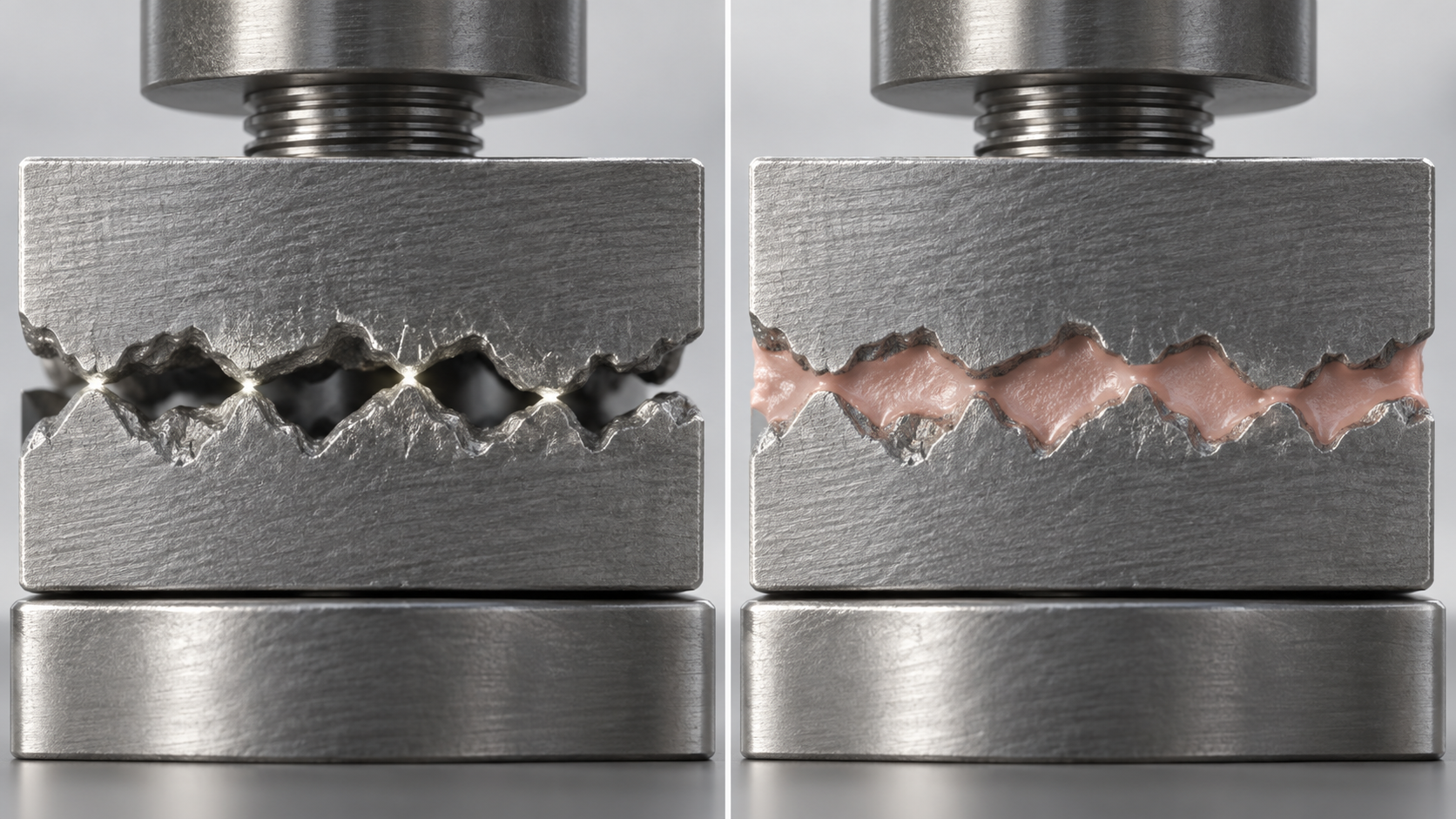
A design that fastens and presses lowers the TIM's thickness L and contact resistance Rc through pressure, as in section 3, but at the price that the clamping load stays on the board and component. Small parts, thin boards and BGAs with solder balls can take only so much force. That is why large pressure is avoided on the die for TIM1 (DuPont).
A design that fixes by bonding needs no fasteners and puts no clamping load on the board. The Henkel catalogue lists, as a feature of thermally conductive adhesives, that they need no fasteners such as clamps or screwsSourced. On the other hand, the thermal conductivities of the adhesives in Henkel's catalogue are 0.8 to 1.8 W/m·K, and even TLB SA3500 in the EV information sheet discussed below is 3.5 W/m·K. That is within the range for greases and pastes that we saw in the TIM article (0.5 to 7 W/m·K, Laird's general statement), not exceptionally highSourced (test conditions are not the same). Henkel's EV product information sheet lists, as thermally conductive adhesives, TLB SA3500, a silicone that is heat-cured (125°C for 20 minutes or 150°C for 10 minutes) at 3.5 W/m·K, and TLB EA1800, a room-temperature-cure epoxy at 1.8 W/m·K with high strengthSourced (September 2020, manufacturer's stated values).
Bonding raises points that materials people should consider (the following is our commentary).
- Stress from CTE difference: the CTE difference between an aluminium heat sink and a chip or ceramic substrate loads the bond layer in thermal cycling. A hard bond layer risks cracking or delamination; a soft one risks displacement or creep. This is why soft silicones are chosen (see our explainers on the coefficient of thermal expansion, and on glass transition and creep)
- Controlling bond-line thickness: L in L/k is the thickness of the bond layer, so thinner is better thermally. But making it thinner makes bond strength, voids and absorbing steps harder. A fibreglass or similar sheet reinforcement (the construction of BOND PLY) can be read as also serving to hold the thickness
- Rework: a bonded heat sink is hard to remove. For parts under evaluation or needing maintenance, pressing on with a TIM can be easier to handle
- Assessing bond strength: tests such as shear and peel are covered in our explainer on adhesive strength testing
So there is a division of use: for heat dissipation, “pressing with a thin TIM” tends to be the more favourable, while for fixing, volume production and small parts, “bonding” tends to be. Which suits depends on the component size, board strength, how it is assembled and the operating temperature (our commentary).
11. Reading performance: a catalogue Rsa is not one number
Seri Lee stresses that no single value of thermal resistance can be assigned to a given heat sink, since it varies with external cooling conditionsSourced. Manufacturers' performance graphs combine a natural-convection curve (temperature rise ΔTsa against heat Q) and a forced-convection curve (thermal resistance against air speed) in one figure; because natural convection is non-linear in heat, ΔT is shown as a function of Q, while forced convection is linear, so Rsa is shown as a function of air speed, he explainsSourced.
- JEDEC JESD51-2A (January 2007) outlines the environmental conditions needed for accuracy and repeatability in a standard junction-to-ambient thermal resistance measurement in natural convection (still air)Sourced. JESD51-6 (March 1999) specifies the environmental conditions for determining the thermal performance of an IC mounted on a standard thermal test board in a forced-convection (moving air) environmentSourced.
- In other words, the performance of a heat sink alone and its performance inside a real enclosure are different things, and here too evaluation in the real device (a TTV and so on) is needed (see our explainer on thermal interface materials).
- The TIM contact conditions (pressure, surface roughness) are also part of the heat sink's measurement conditions, so when comparing the Rsa in different catalogues, check the TIM and pressure conditions (our commentary).
12. Open problems, and what this article could not confirm
(1) We did not build comparison tables by material or by Rsa
The NIST values are evaluations of curve fits near room temperature and change with alloy, temper and purity. Catalogue Rsa values do not share conditions, so we did not build a table comparing heat sinks across products.
(2) Some of the sources are old
Seri Lee's article is from 1995, Iyengar's from 2007 and Shabany's from 2008. Fans and packages have changed, so the numbers are for checking orders of magnitude and trends. The process limits also differ between sources (Fig. 3).
(3) The details of how heat pipes are attached (solder or adhesive) could not be confirmed
We could not confirm primary information on how heat pipes are joined to a base (solder or thermally conductive adhesive) in the sources we read.
(4) Numbers for the long-term reliability of bonded heat sinks are not covered
The thermal-cycling life of the bond layer and delamination figures were not in the documents we read.
(5) The effect of the anodised layer on TIM contact, in numbers, could not be confirmed
ABL says black anodising assists performance, but we could not confirm in our sources any numbers on how the anodised layer affects contact with the TIM.
(6) Technical documents from Japanese heat sink manufacturers are not covered
We could not confirm the content of official technical documents from domestic manufacturers on skiving and similar processes when writing this article, so they are not covered. Furukawa Electric's article was used for the explanation of heat pipes and vapor chambers.
- Thermal resistance adds up in series: Rja = Rjc + Rcs + Rsa. Rcs (the interface) can be changed greatly by how the heat sink is attachedSourced
- Compressing the TIM from 10% to 30% deflection lets the heat sink be about 14% smaller by our calculation (under our assumptions)Our calculation
- Fin efficiency changes with height, h and thermal conductivity. Copper has about twice the thermal conductivity of aluminium (about 201 and about 393 to 398 W/m·K from evaluating the NIST fits)Our calculation
- Each process has different processing limits. Bonded and folded fins have a joining material (a thermal barrier) at the joint; skived fins are one piece with no interfaceSourced
- Radiation carries up to 25% in natural convection, and the same Rsa needs volumes that differ by about ten times with air speedSourced
- There are three ways to attach: TIM plus fastening (a load of 20 to 40 psi), thermally conductive bonding (no fasteners), and metallic joining. A trade-off between heat dissipation, fixing and stress
- Rsa is not one value. It changes with cooling conditions and with the TIM and pressure conditionsSourced
13. Glossary
- Heat sink
- A radiator that passes a component's heat to air or similar from an enlarged surface.
- Rjc / Rcs / Rsa
- Thermal resistance from junction to case, case to heat sink, and heat sink to air (°C/W). Their sum is Rja.
- Fin
- A plate-like or pin-like protrusion of a heat sink that adds surface area.
- Fin efficiency
- The heat a fin actually transfers divided by the heat it would transfer if the whole fin were at the root temperature.
- Spreading resistance
- The resistance that arises when heat spreads from a small source into a larger base.
- Natural / forced convection
- Cooling in which air moves by buoyancy alone / in which the flow is created by a fan or similar.
- Volumetric thermal resistance
- The product of heat sink volume and thermal resistance (cm³·°C/W). A guide for estimating the required volume.
- Skiving
- A process that slices thin layers from a metal block and bends them into fins. Fins and base are one piece.
- Bonded fin
- A structure in which plate fins are joined into slots in a base with epoxy or solder.
- Heat pipe / vapor chamber
- A sealed tube / plate-shaped part that carries heat by evaporating and condensing a working fluid.
- TIM2
- The TIM between the outside of the package and the heat sink.
- JESD51-2A / 51-6
- JEDEC standards for the environmental conditions of thermal tests (natural convection / forced convection).
14. References (primary sources)
- Seri Lee (Aavid) "How to Select a Heat Sink", Electronics Cooling, June 1995 https://www.electronics-cooling.com/1995/06/how-to-select-a-heat-sink/
- Madhusudan Iyengar "Design For Manufacturability Of Forced Convection Air Cooled Fully Ducted Heat Sinks", Electronics Cooling, August 2007 https://www.electronics-cooling.com/2007/08/design-for-manufacturability-of-forced-convection-air-cooled-fully-ducted-heat-sinks/
- Younes Shabany "Simplified Correlations For Radiation Heat Transfer Rate In Plate-Fin Heat Sinks", Electronics Cooling, August 2008 https://www.electronics-cooling.com/2008/08/simplified-correlations-for-radiation-heat-transfer-rate-in-plate-fin-heat-sinks/
- ABL Components "Design factors that influence the thermal performance of a heat sink" (technical page) https://abl-heatsinks.co.uk/technical/design
- ABL Components Material page of "Design factors that influence the thermal performance of a heat sink" (technical page) https://abl-heatsinks.co.uk/technical/material
- NIST (Cryogenic Technologies Group) "Material Properties: 6063-T5 Aluminum (UNS A96063)" https://trc.nist.gov/cryogenics/materials/6063_T5%20Alulminum/6063-T5Aluminum_rev.htm
- NIST (Cryogenic Technologies Group) "Material Properties: OFHC Copper (UNS C10100/C10200)" https://trc.nist.gov/cryogenics/materials/OFHC%20Copper/OFHC_Copper_rev1.htm
- Furukawa Electric "Proper heat dissipation for large quantities of heat using the capillary phenomenon" (Furukawa Electric Platform) https://www.furukawaelectric.com/en/platform/brightening-heat.html
- Panasonic Industry "PGS Graphite Sheet" (product page) https://na.industrial.panasonic.com/products/thermal-management/thermal-management/lineup/thermal-management-products/series/70458
- Henkel Japan Thermal Interface Materials for Heat Dissipation: Thermal Solutions (BERGQUIST product catalogue in Japanese, as of January 2019, PDF) https://dm.henkel-dam.com/is/content/henkel/brochure-bergquist-thermal-interface-materials-jp
- Henkel "Henkel Thermal Interface Solutions for EV Power Conversion Systems" (product information sheet, September 2020, PDF) https://dm.henkel-dam.com/is/content/henkel/Product_information_sheet-thermal-interface-solutions-ev-power-conversion-systems
- Henkel BERGQUIST microTIM mTIM 1013 (product page) https://next.henkel-adhesives.com/us/en/products/thermal-management-materials/central-pdp.html/bergquist-microtim-mtim-1013/SAP_IB-121959.html
- DuPont (Claire K. Wemp, Ph.D.) "Advanced Polymer Formulations for Thermal Management of Electronic Devices" (technical paper, PDF) https://www.dupont.com/content/dam/dupont/amer/us/en/articles/corporate/Advanced%20Polymer%20Formulations%20for%20Thermal%20Management%20of%20Electronic%20Devices_r1_66.pdf
- Indium Corporation "Thermal Interface Materials" (brochure 99342 (A4) R4, PDF) https://www.indium.com/wp-content/uploads/2025/08/TIMs-Brochure-99342-A4-R4.pdf
- Laird (J. Strader et al.) "Thermal Interface Materials (TIMs) and Challenges Faced by TIM Suppliers", TFAWS 2014, NASA Glenn Research Center (presentation, PDF) https://s3vi.ndc.nasa.gov/ssri-kb/static/resources/TFAWS-2014-PT-06.pdf
- JEDEC JESD51-2A "Integrated Circuits Thermal Test Method Environmental Conditions - Natural Convection (Still Air)" (January 2007) https://www.jedec.org/standards-documents/docs/jesd-51-2A
- JEDEC JESD51-6 "Integrated Circuit Thermal Test Method Environmental Conditions - Forced Convection (Moving Air)" (March 1999) https://www.jedec.org/standards-documents/docs/jesd-51-6
- Henkel BERGQUIST GAP PAD TGP 2000 Technical Data Sheet (October 2018, PDF) https://datasheets.tdx.henkel.com/BERGQUIST-GAP-PAD-TGP-2000-en_GL.pdf
15. Claim-to-source audit
| Claim in the text | Basis | Category |
|---|---|---|
| That a heat sink cools by increasing the surface area in contact with the surrounding fluid, and that attachment methods and TIMs affect the final chip temperature; the definition of fin efficiency and why high-conductivity materials matter; ways to reduce spreading resistance (thicker base, higher-conductivity material, vapor chamber or heat pipe); that at 0 to 100°C radiation is small relative to convection; black anodising; the accessory categories (clips and pins, anchors, tape and pads, wire forms) | ABL technical page Reference 4 https://abl-heatsinks.co.uk/technical/design | Sourced |
| That aluminium alloys 1050A, 6060 and 6063 are 229, 166 and 201 W/m·K; that copper has about twice the conductivity of aluminium, three times the density and, depending on the market, four to six times the price; that aluminium can be extruded but copper is machined, skived or soldered; the examples of composite materials (copper-tungsten, AlSiC and so on) | ABL technical page (material) Reference 5 https://abl-heatsinks.co.uk/technical/material | Sourced |
| The Rja = Rjc + Rcs + Rsa thermal circuit; that Rcs depends on surface finish, flatness, mounting pressure, contact area and the type and thickness of the interface material and can be improved greatly; the equation for the required Rsa; ambient 35 to 45°C (external air) or 50 to 60°C (enclosed); that heat transfer across the solid-air interface is the least efficient; the classification of natural and forced convection (buoyancy under 5% above 1 to 2 m/s); Table 2 of volumetric resistance (natural 500-800, 1.0 m/s 150-250, 2.5 m/s 80-150, 5.0 m/s 50-80 cm³·°C/W); Table 3 of optimum fin spacing; that radiation can be up to 25% in natural convection, with paint or anodising; the heat sink types (extrusion: ratio 6 and 1.3 mm minimum, 10:1 and 0.8 (the source writes 0.8 inch) with special dies; bonded: aluminium-filled epoxy, ratio 20 to 40); how to read performance graphs; spreading resistance of 5 to 30% of the total; up to 50% loss from flow bypass; altitude factors; that no single Rsa can be assigned; factory-applied accessories on stampings | Seri Lee article (1995) Reference 1 https://www.electronics-cooling.com/1995/06/how-to-select-a-heat-sink/ | Sourced |
| The descriptions of the processes (extrusion, die casting, bonding, folding, modified die casting, forging, skiving, machining) and Table 1 (minimum fin thickness, maximum H/s, minimum gap, material); the reduction in thermal conductivity from die-casting porosity; that the bonding agent (thermally conductive epoxy or solder) is a thermal barrier; the added resistance at the joints of folded fins; that modified die casting and skiving have no interface. The forced-convection example (aluminium, 0.1 x 0.1 m base, 0.05 m fins, 20 Pa and 0.01 m³/s) with 4 fins/cm, 0.57 mm thickness, 1.93 mm gap, 0.135 °C/W, 186 W and 0.308 kg | Iyengar article (2007) Reference 2 https://www.electronics-cooling.com/2007/08/design-for-manufacturability-of-forced-convection-air-cooled-fully-ducted-heat-sinks/ | Sourced |
| That radiative heat transfer can be a significant portion of the total, particularly in natural convection | Shabany article (2008) Reference 3 https://www.electronics-cooling.com/2008/08/simplified-correlations-for-radiation-heat-transfer-rate-in-plate-fin-heat-sinks/ | Sourced |
| The NIST curve fits for the thermal conductivity of 6063-T5 aluminium (4 to 295 K) and OFHC copper (RRR 50 to 150, 4 to 300 K) | NIST material data Reference 6 https://trc.nist.gov/cryogenics/materials/6063_T5%20Alulminum/6063-T5Aluminum_rev.htmReference 7 https://trc.nist.gov/cryogenics/materials/OFHC%20Copper/OFHC_Copper_rev1.htm | Sourced |
| That a heat pipe is a working fluid vacuum-sealed in a copper tube that carries heat by capillary action; the sintered metal powder wick; that a vapor chamber is a planar, plate-type heat pipe that can be under 0.5 mm thick; the use of heat pipes to link a heat source to cooling fins | Furukawa Electric explanatory page Reference 8 https://www.furukawaelectric.com/en/platform/brightening-heat.html | Sourced |
| That Panasonic's PGS graphite sheet is listed at 700 to 1950 W/m·K on its product page (the direction could not be confirmed) | Panasonic product page Reference 9 https://na.industrial.panasonic.com/products/thermal-management/thermal-management/lineup/thermal-management-products/series/70458 | Sourced |
| The Henkel catalogue: the construction and values of BOND PLY and LIQUI BOND (TBP 850: 0.8 W/m·K, 0.13 to 0.28 mm, acrylic; TBP 1400LMS-HD: 1.4 W/m·K, silicone, heat cure; TLB SA1800: 1.8 W/m·K); that no fasteners are needed; the applications (bonding large BGA packages, power devices and power conversion boards to heat sinks or heat spreaders). As of January 2019 | Henkel Japan catalogue Reference 10 https://dm.henkel-dam.com/is/content/henkel/brochure-bergquist-thermal-interface-materials-jp | Sourced |
| Henkel's EV product information sheet: TLB SA3500 (silicone, heat cure at 125°C for 20 minutes or 150°C for 10 minutes, 3.5 W/m·K) and TLB EA1800 (epoxy, room-temperature cure, 1.8 W/m·K, high strength). September 2020 | Henkel product information sheet Reference 11 https://dm.henkel-dam.com/is/content/henkel/Product_information_sheet-thermal-interface-solutions-ev-power-conversion-systems | Sourced |
| BERGQUIST microTIM mTIM 1013: a durable, thermally conductive thin-film coating applied on the heat sink contact surface, for optical transceivers, for aluminium and copper heat sinks and housings, up to 500 insertion/pull cycles, operating temperature -40 to 175°C | Henkel product page Reference 12 https://next.henkel-adhesives.com/us/en/products/thermal-management-materials/central-pdp.html/bergquist-microtim-mtim-1013/SAP_IB-121959.html | Sourced |
| That 20 to 40 psi is a guide to advantageous compression for TIM2, applied by a clamping mechanism, and that large pressure is avoided on the die for TIM1 | DuPont technical paper Reference 13 https://www.dupont.com/content/dam/dupont/amer/us/en/articles/corporate/Advanced%20Polymer%20Formulations%20for%20Thermal%20Management%20of%20Electronic%20Devices_r1_66.pdf | Sourced |
| That reflowed solder joints are thermally conductive through an intermetallic bond; solders for packages that undergo multiple reflow cycles; the 86 W/m·K of pure indium; that Heat-Spring has no pump-out or bake-out, needs no surface preparation, and suits extruded or unfinished heat sinks and plates with surface imperfections | Indium Corporation brochure Reference 14 https://www.indium.com/wp-content/uploads/2025/08/TIMs-Brochure-99342-A4-R4.pdf | Sourced |
| That graphite sheets, metal foils and thermally conductive plastics are listed as heat spreading materials for thin devices, and that thermally conductive plastics (up to 10 W/m·K insulating, up to 20 W/m·K conductive) are used in complex heat sinks and similar | Laird presentation Reference 15 https://s3vi.ndc.nasa.gov/ssri-kb/static/resources/TFAWS-2014-PT-06.pdf | Sourced |
| That JESD51-2A sets the environmental conditions for a junction-to-ambient thermal resistance measurement in natural convection (still air), and that JESD51-6 sets the environmental conditions for determining the thermal performance of an IC on a standard thermal test board in forced convection (moving air) | JEDEC official pages Reference 16 https://www.jedec.org/standards-documents/docs/jesd-51-2AReference 17 https://www.jedec.org/standards-documents/docs/jesd-51-6 | Sourced |
| The thermal impedance of TGP 2000 (0.040 in; 0.97 at 10% deflection, 0.80 at 30%, °C·in²/W) | Henkel TGP 2000 datasheet Reference 18 https://datasheets.tdx.henkel.com/BERGQUIST-GAP-PAD-TGP-2000-en_GL.pdf | Sourced |
| Rcs at 40 x 40 mm (0.39 and 0.32 °C/W), Rsa (0.41 and 0.48 °C/W), the split of the temperature rise (12.0 / 23.5 / 24.5 K and 12.0 / 19.4 / 28.6 K), the ratio of required volumes (about 0.86, about 14% smaller); the estimated volumes (natural 1223 to 1957, 1.0 m/s 367 to 611, 2.5 m/s 196 to 367, 5.0 m/s 122 to 196 cm³) | Our calculation. Assumptions: 60 W, Tj 100°C, Ta 40°C, Rjc 0.2 °C/W (assumed), area 2.48 in², volume = volumetric resistance / Rsa | Our calculation |
| The fin efficiency (about 0.87 for aluminium and 0.93 for copper at 30 mm height, 1 mm thickness and h = 50); eta = tanh(mL)/mL, m = sqrt(2h/kt) | Our calculation. The standard straight-fin equation with an adiabatic tip. h (10 and 50 W/m²K) and the 1 mm thickness are assumptions; k is evaluated from the NIST fits (201 for aluminium, 395 for copper W/m·K) | Our calculation |
| About 201 W/m·K for 6063-T5 aluminium and about 393 to 398 W/m·K for OFHC copper at 295 K; that copper is about twice aluminium | Our calculation. The NIST curve fits evaluated at 295 K (fit error about 2%) Reference 6 https://trc.nist.gov/cryogenics/materials/6063_T5%20Alulminum/6063-T5Aluminum_rev.htmReference 7 https://trc.nist.gov/cryogenics/materials/OFHC%20Copper/OFHC_Copper_rev1.htm | Our calculation |
| The radiative heat transfer coefficient (about 7.2 W/m²K at emissivity 0.9 and about 0.8 at 0.1); that 20 and 40 psi on 40 x 40 mm are about 220 N and 440 N | Our calculation. h_r = eps x sigma x (Ts² + Ta²)(Ts + Ta), Ts = 343 K, Ta = 313 K, sigma = 5.67e-8 W/(m²·K⁴). Load = pressure x area (1 psi = 6.895 kPa) | Our calculation |
| The reading that a TIM acts on heat flow as a separate part; that the idea of interface resistance applies inside the heat sink (bonding agent, porosity, one-piece machining); that thermal conductivity and CTE are separate axes; that the choice of process is a choice among interface, defects and processing limits; the division between fastening and bonding (heat dissipation, fixing, volume production, stress, rework); the reading on controlling bond-line thickness | This article's own framing and commentary based on published content. Not views expressed by the companies or institutions | Commentary |
| How heat pipes are joined to the base; the long-term reliability of bonded heat sinks (thermal-cycling life and delamination of the adhesive layer); the relationship between the anodised layer and the TIM; technical documents from Japanese manufacturers; whether the minimum fin thickness in Seri Lee's table is in mm or inches | Not covered, because this article could not confirm them. The 0.8-inch notation in Seri Lee's article is read here as mm | Commentary |
| That Figs. 1 to 4 are explanatory drawings rather than cross-section photographs or measurement results; that the hero image and Fig. 5 are AI-generated images | A note by this article | Commentary |
Last updated 3 October 2026. Sources are limited to primary material (technical articles in a trade journal, NIST materials data, manufacturers' technical documents, catalogues and product pages, standards bodies' pages, a conference presentation). Because the article includes structural readings and materials-design interpretations, those are marked as Commentary and kept separate from sourced fact. How heat pipes are joined, the long-term reliability of bonded heat sinks, numbers for the anodised layer and the TIM, and technical documents from Japanese manufacturers are not covered, because they could not be confirmed in primary sources. All figures are for explanation. Figs. 1 to 4 are vector drawings (Figs. 1, 2 and 4 include our calculation), and the hero image and Fig. 5 are AI-generated images; none of them shows an actual cross-section photograph, measurement result or real product.