TECHNOLOGY EXPLAINER
Adhesive Strength Testing
— An “N/mm²” Figure Always Comes With Conditions
Adhesive strength is not a single quantity. Each way of loading a joint — shear, peel, tension, impact — has its own ISO, ASTM and JIS test method. The abstracts of the standards themselves state that the test procedure does not provide design information. Even for the same adhesive, a change of adherend, surface preparation, cure, temperature or test method can move the number severalfold. So before the number, look at the fracture surface.
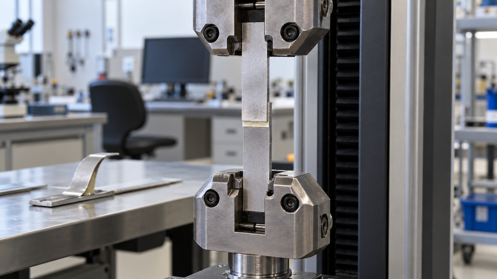
- What adhesive strength testing is (the short version)
- A map of the tests — standards split by how the load is applied
- Shear tests — what a lap-shear specimen really measures
- Peel tests — force per unit width, not stress
- Tension, cleavage, impact, creep and fatigue
- A materials engineer's view (1): look at the fracture surface before the number
- Our calculation: how far the number moves for one adhesive
- A materials engineer's view (2): the number is made by the specimen, the preparation, the cure and the environment
- Ageing tests — humid heat hits hardest
- Scatter and how to report
- An electronics example: die shear
- Limits and what could not be confirmed / Glossary / Primary sources / Claim-to-source audit
Sourced = stated in published material (link given)
Our calculation = a figure this article derived, with the assumptions spelled out
Not yet confirmed = a plan or proposal with no confirmed record
Structural readings and materials-design interpretations are marked separately as Commentary.
Strength and other values are given together with test method, conditions and source; values from manufacturers' data sheets are labelled manufacturer's stated value (typical). Standards are paywalled, so this article keeps to what the official pages show: number, title and scope. It does not rank any product or company.
1. What adhesive strength testing is (the short version)
“Adhesive strength” tempts us to think of one number. But a bonded joint breaks differently depending on how it is loaded: force along the face (shear), peeling from one end (peel), pulling straight off the face (tension), opening a crack (cleavage), a sudden blow (impact), repeated loading (fatigue) and a load held for a long time (creep). Each of these has its own ISO, ASTM and JIS test method.
- Not one quantity: shear strength (N/mm²) and peel strength (N/mm, force per unit width) differ even in unit. Two numbers for the same adhesive cannot be ranked against each otherSourced (Chapter 4)
- A number for comparison, not a design value: ASTM D1002 states that the test is primarily comparative and that misusing its values as design-allowable stresses for structural joints could lead to product failure, property damage and human injury. The abstract of ISO 4587 likewise says the procedure does not provide design informationSourced
- A number for the whole system: for the same adhesive, the number moves severalfold with adherend, surface preparation, cure, test temperature and test method (3M and Henkel data sheets, Chapter 7). A number that travels without its conditions cannot be reproducedSourced
An adhesive strength figure is not a property of the adhesive. It is a composite of adhesive + adherend + surface preparation + cure + test conditions. And it only means something when you add where the joint broke — cohesive failure, adhesive (interfacial) failure or substrate failure.
A note on terms: the Japanese phrase “joint strength test” (setsugo kyodo shiken) is also used broadly for welds, solder joints, screwed and crimped joints (our commentary). This article covers joints bonded with an adhesive. Adhesive types and design are covered in our explainer on adhesives.
2. A map of the tests — standards split by how the load is applied
The table below lists the main standards, their titles and their current status, as shown on each body's official page when checked in October 2026Sourced.
| Test | Standard (number, edition) | Title (as on the official page) | Status |
|---|---|---|---|
| Shear | ISO 4587:2003 | Adhesives — Determination of tensile lap-shear strength of rigid-to-rigid bonded assemblies | Current (confirmed 2021) |
| JIS K 6850:1999 | Adhesives — Determination of tensile lap-shear strength of rigid-to-rigid bonded assemblies (title in Japanese) | Current (confirmed 2023). Modified adoption (MOD) of ISO 4587:1995 | |
| ASTM D1002-10(2019) | Standard Test Method for Apparent Shear Strength of Single-Lap-Joint Adhesively Bonded Metal Specimens by Tension Loading (Metal-to-Metal) | Active | |
| ASTM D3163-01(2023) | Standard Test Method for Determining Strength of Adhesively Bonded Rigid Plastic Lap-Shear Joints in Shear by Tension Loading | Active | |
| ASTM D3165-07(2023) | Standard Test Method for Strength Properties of Adhesives in Shear by Tension Loading of Single-Lap-Joint Laminated Assemblies | Active | |
| ISO 13445:2003 | Adhesives — Determination of shear strength of adhesive bonds between rigid substrates by the block-shear method | Current (confirmed 2021) | |
| Peel | ISO 11339:2022 | Adhesives — T-peel test for flexible-to-flexible bonded assemblies | Current (4th edition) |
| JIS K 6854-3:1999 | Adhesives — Determination of peel strength of bonded assemblies — Part 3: T-peel (title in Japanese) | Current (confirmed 2025). Identical (IDT) to ISO 11339:1993 | |
| ASTM D1876-08(2023) | Standard Test Method for Peel Resistance of Adhesives (T-Peel Test) | Active | |
| ISO 8510-2:2006 | Adhesives — Peel test for a flexible-bonded-to-rigid test specimen assembly — Part 2: 180° peel | Current (confirmed 2025) | |
| JIS K 6854-1:1999 / -2:1999 | Adhesives — Determination of peel strength of bonded assemblies — Part 1: 90° peel / Part 2: 180° peel (titles in Japanese) | Current (confirmed 2025) | |
| ISO 4578:1997 | Adhesives — Determination of peel resistance of high-strength adhesive bonds — Floating-roller method | Current (confirmed 2023) | |
| ASTM D3167-10(2025) | Standard Test Method for Floating Roller Peel Resistance of Adhesives | Active | |
| Tension | ASTM D2095-96(2023) | Standard Test Method for Tensile Strength of Adhesives by Means of Bar and Rod Specimens | Active |
| JIS K 6849:1994 | Testing methods for tensile strength of adhesive bonds (title in Japanese) | Current (confirmed 2023). Not equivalent (NEQ) to ISO 6922:1987 | |
| Cleavage | ASTM D3433-99(2020) | Standard Test Method for Fracture Strength in Cleavage of Adhesives in Bonded Metal Joints | Active |
| Impact | ISO 9653:1998 | Adhesives — Test method for shear impact strength of adhesive bonds | Current (confirmed 2021) |
| ISO 11343:2019 | Adhesives — Determination of dynamic resistance to cleavage of high-strength adhesive bonds under impact wedge conditions — Wedge impact method | Current (confirmed 2024) | |
| ASTM D950-03(2020)e1 | Standard Test Method for Impact Strength of Adhesive Bonds | Active | |
| Creep, fatigue | ASTM D2294-96(2024) | Standard Test Method for Creep Properties of Adhesives in Shear by Tension Loading (Metal-to-Metal) | Active |
| ISO 9664:1993 | Adhesives — Test methods for fatigue properties of structural adhesives in tensile shear | Current (confirmed 2021) | |
| Ageing | ISO 9142:2003 | Adhesives — Guide to the selection of standard laboratory ageing conditions for testing bonded joints | Current (confirmed 2021) |
| ASTM D1151-00(2022) | Standard Practice for Effect of Moisture and Temperature on Adhesive Bonds | Active | |
| Failure modes | ISO 10365:2022 | Adhesives — Designation of main failure patterns | Current (2nd edition) |
| JIS K 6866:1999 | Adhesives — Designation of main failure patterns (title in Japanese) | Current (confirmed 2023). Identical (IDT) to ISO 10365:1992 | |
| ASTM D5573-99(2019) | Standard Practice for Classifying Failure Modes in Fiber-Reinforced-Plastic (FRP) Joints | Active | |
| Preparation, use of results | ASTM D2651-01(2024) | Standard Guide for Preparation of Metal Surfaces for Adhesive Bonding | Active |
| ASTM D4896-01(2024) | Standard Guide for Use of Adhesive-Bonded Single Lap-Joint Specimen Test Results | Active |
All Sourced (official pages of ISO, ASTM and the Japanese Standards Association [References 1–30], checked October 2026). The standards are paywalled, so details such as specimen dimensions, speeds and number of specimens were not checked.
According to the Japanese Standards Association's pages, JIS K 6850:1999 is based on ISO 4587:1995, JIS K 6854-3:1999 on ISO 11339:1993 and JIS K 6866:1999 on ISO 10365:1992Sourced. The current ISO editions are 4587:2003, 11339:2022 and 10365:2022Sourced. Because the standards are paywalled, this article could not check how the edition difference affects results. In a test report, give the edition (year) as well as the standard number (our commentary).
3. Shear tests — what a lap-shear specimen really measures
The most widely used adhesive strength test overlaps the ends of two plates, bonds them, and pulls both ends: the tensile lap-shear test. ISO 4587 specifies how to determine the tensile lap-shear strength of rigid-to-rigid bonded assembliesSourced; ASTM D1002 specifies how to determine the apparent shear strength of adhesives for bonding metals on a standard single-lap specimenSourced. The word “apparent” in the title says what kind of test this is.
The “Significance and Use” section of ASTM D1002 is frank about the limits of the testSourced.
- The test is primarily comparative. It is, however, useful as a discriminator for differences in adherend surface preparation and in the environmental durability of an adhesive
- Using the values as design-allowable stresses for structural joints could lead to product failure, property damage and human injury
- The apparent shear strength from a small specimen can differ if the adherends or the bonding process differ. Adherend and adhesive swell and shrink differently with temperature and moisture, generating internal stress when the environment changes
ASTM D4896, the guide to using single-lap results, also says that single-lap specimens are economical, practical and the most widely used for development, evaluation and comparative studies, including manufacturing quality control. At the same time it notes that thin-adherend single-lap specimens have many deficiencies and that other, harder-to-make specimens have been developed to estimate the “true shear strength” of an adhesive more accuratelySourced. One example is ASTM D3983, which measures the strength and shear modulus of non-rigid adhesives with a thick-adherend tensile-lap specimen; it says the method can give values of accuracy suitable for design engineers (for building assemblies bonded with non-rigid adhesives)Sourced.
A real set of specimen conditions — from a manufacturer's data sheet
The standard dimensions are in the paywalled text, but 3M's data sheet states its own lap-shear test conditions concretely, citing ASTM D1002 and ISO 4587Sourced.
| Item | As stated in the 3M Scotch-Weld DP460NS data sheet (manufacturer's stated value) |
|---|---|
| Specimen | 25 mm (1 in) wide, 12.7 mm (0.5 in) overlap, 25 mm × 102 mm (1 in × 4 in) adherends |
| Adherend thickness | Steel 1.5 mm; other metals 1.3–1.6 mm; rubber and plastic 3.2 mm |
| Bondline thickness | 0.13–0.20 mm (5–8 mil) |
| Jaw separation rate | Metal 2.5 mm/min, plastic 51 mm/min, rubber 510 mm/min |
| Recording of failure | Cohesive (CF), adhesive (AF), mixed (MF) and substrate (SF) failure are distinguished |
All Sourced (3M DP460NS data sheet, English-US, revised September 2024 [Reference 31]). These are the manufacturer's own test conditions, not the dimensions or speeds a standard requires (the standards' text was not checked).
Mean shear stress is the failure load F divided by the bonded area (width b × overlap l)Our calculation.
- Formula: τ = F ÷ (b × l)
- Example: the 3M data sheet gives 4,500 lb/in² (≈ 31.0 MPa) for etched aluminium after 24 h of cure. Assumption: 1 in wide, 0.5 in overlap (as stated in the data sheet), so the bonded area is 0.5 in². F = 4,500 × 0.5 = 2,250 lbf = about 10.0 kN
- Units: 1 N/mm² = 1 MPa. 1 lb/in² ≈ 0.006895 MPa
Assumptions and limits: this is a mean, assuming the stress is uniform over the whole bond. As Fig. 2 shows, the real stress concentrates at the ends. For specimens whose adherends bend, plate thickness and yield strength also change the failure load.
What moves shear strength — an experimental design in a paper
da Silva and co-workers sorted the factors affecting single-lap joint strength with the Taguchi methodSourced (International Journal of Adhesion and Adhesives, 2009 [Reference 34]). They varied eight variables: adhesive toughness and thickness, adherend yield strength and thickness, overlap length, test speed, surface preparation and durability (environment). An 18-run matrix, each run repeated three times, showed that overlap length has the largest effect. The paper adds that strength prediction is hardest when the adhesive is brittle and the overlap is long, and that data and design criteria for long-term temperature and humidity effects are lacking.
In other words, overlap, adherend thickness, bondline thickness and test speed are all “variables that move the number”. If they are not reported, nobody else can reproduce the result.
4. Peel tests — force per unit width, not stress
A peel test measures the resistance as the joint is separated progressively from one end. ISO 11339 determines the peel resistance of an adhesive from the peeling force of a T-shaped assembly of two flexible adherends (T-peel); the method was originally developed for metal adherends and can be used with other flexible adherendsSourced. ASTM D1876 pulls the same T specimen in a tensile tester and determines the peel resistance over a specified length of the bond line after the initial peakSourced.
What sets peel apart from shear is the unit. Peel is expressed not as stress per bonded area but as force per unit width (N/mm, lb/in of width). 3M's data sheet also gives peel in lb/in of widthSourced.
| Test (3M DP460NS, aluminium) | Test temperature | Value in the data sheet (manufacturer's stated value) | Converted to N/mm |
|---|---|---|---|
| T-peel (ASTM D1876, jaw rate 508 mm/min, 25 mm wide) | −55 °C | 3–5 lb/in width | about 0.5–0.9 |
| 23 °C | 60 lb/in width | about 10.5 | |
| 82 °C | 20 lb/in width | about 3.5 | |
| Bell peel (ASTM D3167 as cited, jaw rate 15 cm/min, 12.7 mm wide) | −55 °C | 19 lb/in width | about 3.3 |
| 23 °C | 77 lb/in width | about 13.5 | |
| 82 °C | 39 lb/in width | about 6.8 |
Peel values are Sourced (3M DP460NS data sheet [Reference 31], manufacturer's stated value). The conversion to N/mm (1 lb/in ≈ 0.1751 N/mm) is Our calculation.
For the same adhesive on the same aluminium, T-peel is 60 lb/in of width at 23 °C but 3–5 at −55 °C and 20 at 82 °CSourced. It falls at both low and high temperature: the maximum sits near room temperature. That contrasts with shear, which does not fall at low temperature but falls sharply at high temperature (Chapter 7).
The data sheet gives no reason. As commentary: peel strips the joint progressively while bending the adherends, so what matters is whether the bondline can deform tenaciously, absorbing energy. A double reason is plausible — the adhesive turns brittle at low temperature, and its modulus and strength fall at high temperature (our inference). The glass transition (Tg) is covered in our explainers on epoxy resins and on glass transition and creep.
Also, T-peel and bell peel give different numbers for the same adhesive on the same aluminium (60 and 77 at 23 °C), because the specimen shape, adherend thickness and speed differ. ASTM D3167 itself says that variation in adherend thickness generally influences the test values and that thickness should be set in the material specificationSourced. Peel values can only be compared with the method name and the adherend thickness attached.
5. Tension, cleavage, impact, creep and fatigue
Beyond shear and peel, the standards cover further uses. The table summarises what each test is for, as described on each standard's official pageSourced.
| Test | Standard | What the official page says (summary) |
|---|---|---|
| Tension | ASTM D2095 | Determines the relative tensile strength of adhesives with butt-joined bar and rod specimens. Useful for specification acceptance, service evaluation, manufacturing control, research and development, but not considered significant for applications that differ from the test in rate, direction and type of loading |
| Cleavage | ASTM D3433 | Determines the fracture strength in cleavage of adhesives in bonded metal joints. A note says the shape of the load record differs according to whether the crack advances steadily or in a run-arrest manner |
| Impact (shear) | ISO 9653, ASTM D950 | ASTM D950: a bond may fail under a sudden impact load yet not under a slowly applied load of the same or greater force. The test compares how sensitive adhesives are to suddenly applied loads |
| Impact (cleavage) | ISO 11343 | Dynamic resistance to cleavage of high-strength bonds under impact wedge conditions. Sheet metal or fibre-reinforced plastic substrates, as used in automotive applications, can be chosen |
| Creep | ASTM D2294 | Creep properties of adhesives under tensile shear loading. Useful in research and development for comparing the effects of formulation, temperature, moisture and duration of loading |
| Fatigue | ISO 9664 | Cycles the specimen with an alternating stress superposed on a static mean stress and determines the number of cycles to failure |
All Sourced (official ISO and ASTM pages [References 5, 6, 10, 13, 17–19]). The summaries are this article's English paraphrase.
Shear and tension look at the stress at failure (strength), whereas cleavage (D3433) looks at the joint from the side of how readily a crack advances — the energy needed to fracture. That is why G1c and G1a (symbols for the energy release rate at crack initiation and arrest) appear on the ASTM D3433 page (our commentary).
Whether an adhesive is hard and brittle (high strength but a running crack) or tough (the same strength but the crack arrests) cannot be seen from a stress number alone. Impact, fatigue and creep tests are where that difference shows. When you evaluate rubber-toughened epoxies or soft, elastic adhesives (urethanes, silicones), choosing on shear strength alone is a mistake. Our explainers on glass transition and creep, and on polyurethanes and elastomers, are useful companions.
6. A materials engineer's view (1): look at the fracture surface before the number
When a test is over, look at the broken surfaces before you copy the number from the machine. The same “20 N/mm²” means entirely different things depending on whether the adhesive split inside, the joint peeled at the interface, or the adherend failed first.
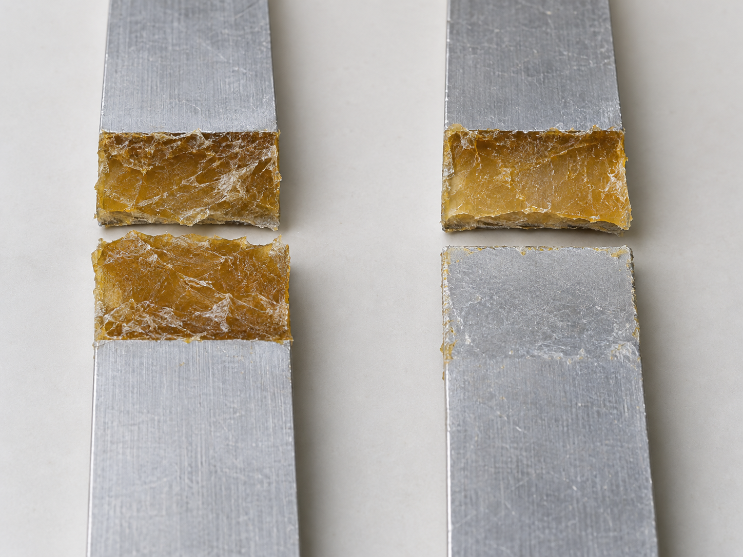
The standards follow the same ideaSourced.
- ISO 10365:2022 specifies the designations for the main failure patterns of bonded assemblies and illustrates their appearance in diagrams. It applies to all mechanical tests on a bonded assembly, whatever the adherends and adhesive
- JIS K 6866:1999 is the Japanese standard identical in content (IDT) to ISO 10365:1992
- ASTM D5573 defines failure modes for fibre-reinforced-plastic (FRP) joints — adhesive, cohesive, thin-layer cohesive, fibre-tear, light-fibre-tear, stock-break and mixed failure. Classification is by visual observation without a microscope, and the practice does not address which failure mode is acceptable. Mixed failure is expressed as shares, for example “32 % adhesive failure, 68 % fibre-tear”
A substrate-failure (SF) number is a lower bound on the strength of the bond. The adherend failed first, so the bond may have been able to carry more. 3M's data sheet also marks the fibre-reinforced plastic value with “SF”Sourced. Conversely, a high number from adhesive (interfacial) failure is hard to trust, because a small difference in surface preparation or contamination may bring the next specimen far lower (our commentary).
The fracture surface also tells you what to do next. If it is adhesive failure, revisit surface preparation, primer and wetting (surface energy). If it is cohesive failure, the interface is sound and the adhesive itself (crosslink density, Tg, filler, toughening) sets the strength. If it is substrate failure, that adherend cannot measure the adhesive's strength, so change the test method or make the adherend thicker or stronger (our commentary).
Same adhesive, same adherend, a different conclusion with a different test — Henkel's LOCTITE 401 data sheet
Henkel's data sheet for LOCTITE 401, a cyanoacrylate adhesive (February 2012 edition), lists values for the same plastic adherends tested by ISO 4587 (lap shear) and by ISO 13445 (block shear). The data sheet marks values that ended in substrate failure with an asterisk (*).
| Adherend | ISO 4587 (lap shear) N/mm² | ISO 13445 (block shear) N/mm² | Reading (our commentary) |
|---|---|---|---|
| Polycarbonate | 9.6 * | 11 | Substrate failure in lap shear. No mark in block shear, and a somewhat higher value |
| ABS | 7.5 * | 23 * | Substrate failure in both. The number reflects the ABS itself (a lower bound for the adhesive) |
| PVC | 10 * | 2.6 | Substrate failure at 10 or more in lap shear, but 2.6 with no mark in block shear. The conclusion changes with the test |
| Phenolic resin | 12.6 * | 21.3 * | Substrate failure in both. The stress at which the adherend fails differs between the two tests |
All Sourced (LOCTITE 401 data sheet, February 2012, Slovak-language edition [Reference 33], manufacturer's stated value (typical); cured 72 h at 22 °C. * = value the data sheet marks as substrate failure). The same data sheet gives, for ISO 4587, also steel (grit-blasted) 20, aluminium (etched) 12.4 and zinc dichromate 2.5 N/mm².
The 2.6 N/mm² for PVC can be read as a value at which the bond failed before the adherend did. For the same adhesive and the same adherend, one test ended in substrate failure at 10 N/mm² or more and the other failed at 2.6 N/mm²Sourced. The data sheet does not say why. The way the load is applied (block shear uses a thick adherend; in lap shear a thin plate bends) may be one reason, but this article has not confirmed it (inference). Either way, a “substrate-failure number” must not be set beside a number from another test method.
7. Our calculation: how far the number moves for one adhesive
The data sheet for 3M's two-part epoxy adhesive Scotch-Weld DP460NS lists lap-shear strength of the same adhesive for different surface preparations, test temperatures, cure times and adherends. We convert the values in the Portuguese edition (April 2020; kgf/cm²) and the English edition (September 2024; lb/in²) to MPa and set them side by sideOur calculation.
| Condition changed | How the value moves (DP460NS, lap shear) | Ratio to the reference (our calculation) |
|---|---|---|
| Surface preparation (aluminium, 23 °C) | Etched 316 → solvent wipe + abrade 188 → alkaline degrease only 162 kgf/cm² | With etched = 100 %: 59 %, 51 % |
| Test temperature (aluminium) | −55 °C 345, 23 °C 327, 82 °C (15 min) 96, 82 °C (4 h) 188, 121 °C (15 min) 30 kgf/cm² | With 23 °C = 100 %: −55 °C 106 %, 82 °C (15 min) 29 %, 121 °C (15 min) 9 % |
| Cure time (23 °C) | 4 h 3, 6 h 68, 24 h 316 kgf/cm² | With 24 h = 100 %: 6 h 22 %, 4 h 1 % |
| Cure temperature (60 °C) | 60 °C, 15 min: 342 kgf/cm² | 108 % of the 23 °C, 24 h value (316) |
Values are Sourced (3M DP460NS data sheet, Portuguese edition, April 2020 [Reference 32], manufacturer's stated value). Ratios are Our calculation (rounded).
The English edition (September 2024) has a table by adherend, again for the same adhesive and the same lap shear (ASTM D1002 and ISO 4587, 23 °C, 7-day cure).
| Adherend (preparation) | Data-sheet value lb/in² | Converted to MPa | Note |
|---|---|---|---|
| Copper (MEK/abrade/MEK) | 4,400 | 30.3 | Metals at 2.5 mm/min |
| Cold-rolled steel (same) | 3,600 | 24.8 | |
| Brass (same) | 3,400 | 23.4 | |
| Aluminium (same) | 2,670 | 18.4 | Etched aluminium (24 h cure) is 4,500 ≈ 31.0 |
| Stainless steel (same) | 2,400 | 16.5 | |
| Fibre-reinforced plastic (IPA wipe/abrade/IPA wipe) | 1,379 | 9.5 | Substrate failure (SF). Plastics at 51 mm/min |
| ABS (same) | 572 | 3.9 | |
| Polycarbonate (same) | 390 | 2.7 | |
| PVC (same) | 313 | 2.2 | |
| Acrylic (PMMA) (same) | 270 | 1.9 |
Values are Sourced (3M DP460NS data sheet, English edition, September 2024 [Reference 31], manufacturer's stated value). MPa is Our calculation (1 lb/in² = 0.006895 MPa). The jaw speed for plastics differs from that for metals (Chapter 3).
- Adherend: from the highest (copper, 4,400) to the lowest (acrylic, 270), about 16-fold (4,400 ÷ 270 = 16.3). Between the highest and lowest metals (copper and stainless steel), about 1.8-fold
- Surface preparation: on the same aluminium, alkaline degreasing alone gives about half the etched value (162 ÷ 316 = 0.51)
- Temperature: at 82 °C (15 min) about 30 % of the room-temperature value (96 ÷ 327 = 0.29). At the same 82 °C but with the “4 h” entry it recovers to about 60 % (188 ÷ 327 = 0.57)
- Cure: at 23 °C, 6 h gives about 20 % of the 24 h value and 4 h almost nothing. At 60 °C, 15 min exceeds the 24 h value
Assumptions and limits: these are values for 3M's two-part epoxy DP460NS, and all they show is that on aluminium the etched preparation gave the highest value. They do not carry over to other adhesives or other lots. Note also that the same “etched aluminium, 23 °C” condition appears as 327 kgf/cm² in the temperature table and 316 in the adherend table (about 3.5 % apart). The data sheet gives no reason, so even within one data sheet, tables can differ by a few per cent. The English edition's aluminium (solvent wipe + abrade) 2,670 lb/in² = 18.4 MPa and etched 4,500 lb/in² = 31.0 MPa agree on conversion with the Portuguese edition's 188 and 316 kgf/cm² (our calculation).
In the table the 82 °C value is 96 kgf/cm² at 15 min, 127 at 30 min, 185 at 60 min and 188 at 4 h — the longer the time, the strongerSourced. The data sheet gives no reason. If we read these times as dwell before the test, then as commentary: an adhesive cured at room temperature post-cures on heating, crosslinking further and raising its Tg (our inference). If so, strength at high temperature depends not only on the temperature but on how long the joint has been held there. The link between Tg and degree of cure is covered in our explainer on epoxy resins. This is why a test report should state the dwell time at the test temperature.
8. A materials engineer's view (2): the number is made by the specimen, the preparation, the cure and the environment
Here are the examples so far, sorted by factor: a list of “variables that move the number”, drawn from the data sheets and standardsSourced.
| Factor | Example, with source | From the materials side (our commentary) |
|---|---|---|
| Adherend material | For the same adhesive (DP460NS): copper 30.3 MPa, aluminium 18.4, ABS 3.9, acrylic 1.9 (3M, manufacturer's stated value, Chapter 7) | Surface energy and chemical compatibility, plus the adherend's own strength and modulus. Low-surface-energy plastics need a primer (Henkel's data sheet recommends LOCTITE 770 or 7239 primer) |
| Surface preparation | Etched 31.0 MPa against alkaline degrease only 15.9 (3M). ASTM D2651 lists mechanical and chemical preparations for aluminium, stainless steel, carbon steel, titanium, magnesium and copper alloys | Removing contamination, controlling the oxide film, roughness at the interface. 3M's data sheet asks that surfaces be bonded or primed as soon as possible after preparation to avoid contamination and damage |
| Cure conditions | At 23 °C, 6 h gives about 20 % of the 24 h value; at 60 °C it is reached in 15 min (3M) | Without crosslinking, neither cohesion nor interfacial reaction is adequate. A value measured before “full cure” only shows how strength is building up |
| Test temperature, dwell time | 82 °C (15 min) about 30 % of room temperature, 121 °C (15 min) about 10 % (3M). T-peel falls at both −55 °C and 82 °C | The relation between Tg and service temperature, and post-cure. The same adhesive has both a “hill” and a “valley” against temperature |
| Test speed | 3M uses 2.5 mm/min for metal, 51 for plastic and 510 for rubber, changing the speed with the adherend | Polymers are viscoelastic: the faster you pull, the stiffer and more brittle they behave. With different speeds, numbers cannot be compared |
| Geometry (overlap, thickness, bondline) | In da Silva et al.'s experimental design, overlap length is the largest factor (from the paper's abstract). ASTM D3167 says adherend thickness influences the value | Plate bending and the peak stress at the ends (Fig. 2). Thicker bondlines also change how volume shrinkage and thermal-expansion mismatch stress act |
| Mixing, application, auxiliaries | 3M: inaccurate (manual) mixing affects results (note in the Portuguese edition). Henkel: using an activator may reduce final strength, so test it | A drift in a two-part mix ratio becomes unreacted groups and a shift in crosslink density. An auxiliary may speed cure yet weaken the interface |
| Conditioning, storage | 3M: except for the strength build-up tests, joints are cured 7 days at 23 °C and 50 % relative humidity before testing or ageing (Portuguese edition) | Adherends and adhesive that have absorbed moisture change in Tg and interfacial state. Where the specimens sat the day before shows up in the number |
Sources are Sourced (3M DP460NS data sheet [References 31, 32], LOCTITE 401 data sheet [Reference 33], ASTM D2651 and D3167 [References 21, 16], da Silva et al. [Reference 34]). The right-hand column is our commentary.
When adhesive strength comes out low, there are three entrances from the materials side (our grouping).
- Interface (wetting and adhesion): if the fracture is adhesive failure (AF), start here: surface energy, contamination, oxide film, primer, the time from preparation to bonding
- The adhesive itself (cohesion): if the fracture is cohesive failure (CF), the issue is crosslink density, Tg, filler and toughening. Incomplete cure shows up here. See our explainers on epoxy resins, and on polymer blends and fillers
- Stress (cure shrinkage and thermal mismatch): the difference in thermal expansion between adherend and adhesive, and cure shrinkage, create internal stress before the test even starts. ASTM D1002 too says that this difference in expansion produces internal stress when the environment changesSourced. See our explainer on the coefficient of thermal expansion
When you hear a number, ask back: on which adherend, with what preparation, cured how many days, at what temperature, and how did it break? That is the basic way to live with an adhesive strength number.
9. Ageing tests — humid heat hits hardest
A bonded joint is more of a problem after exposure to moisture, heat and chemicals than just after manufacture. ISO 9142 is a guide to selecting standard laboratory ageing conditions for climatic or chemical exposure of bonded joints. It applies to bonded assemblies and can be used as a set of tests to evaluate an adhesive. But the standard cautions that results are not necessarily applicable to determining the service life of a bonded assembly, because there is no direct relation between test results and behaviour over time in service; for specific applications, experience may allow a correlation to be establishedSourced.
ASTM D1151 defines continuous exposure at specified moisture and temperature and expresses performance as strength retained after exposure ÷ original strengthSourced.
3M's data sheet (Portuguese edition) gives lap-shear values for etched aluminium tested at 23 °C after environmental exposureSourced. We converted the DP460NS values to MPa and calculated the ratio to the 23 °C, 50 % RH, 30-day valueOur calculation.
| Environment (tested at 23 °C after exposure) | kgf/cm² | MPa | vs 23 °C, 50 % RH |
|---|---|---|---|
| 23 °C, 50 % RH, 30 days (reference) | 384 | 37.7 | 100 % |
| Distilled water, 30 days immersed | 320 | 31.4 | 83 % |
| Water vapour 49 °C, 100 % RH, 30 days | 276 | 27.1 | 72 % |
| Water vapour 93 °C, 100 % RH, 14 days | 237 | 23.2 | 62 % |
| Coolant/water (50/50), 82 °C, 30 days immersed | 309 | 30.3 | 80 % |
| Isopropyl alcohol, 23 °C, 30 days immersed | 374 | 36.7 | 97 % |
| MEK, 23 °C, 30 days immersed | 281 | 27.6 | 73 % |
| Salt spray (5 %, 35 °C), 30 days | 366 | 35.9 | 95 % |
| Skydrol LD-4, 66 °C, 30 days immersed | 369 | 36.2 | 96 % |
Values are Sourced (3M DP460NS data sheet, Portuguese edition, April 2020 [Reference 32], manufacturer's stated value). The data sheet notes that the figures are actual batch values and may be higher than the published values elsewhere. MPa and ratios are Our calculation.
The largest fall in this table is for water vapour at 93 °C and 100 % RH for 14 days (about 62 %)Our calculation. Humid heat is harsher than immersion in distilled water at room temperature (83 %) or salt spray (95 %). Among solvents, isopropyl alcohol made almost no difference (97 %) and MEK about 73 %.
As commentary: water is not only absorbed and plasticises the adhesive; it also creeps in at the interface between the metal's oxide film and the adhesive and weakens adhesion, and temperature accelerates this. So after a humid-heat test, alongside the strength number, check whether the fracture has changed from cohesive to adhesive failure (our commentary and inference). The same data sheet also gives an example in which two grades of one family, DP460 Off-White and DP460NS, respond differently to the same exposure (260 and 369 kgf/cm² after Skydrol)Sourced. Even within a family, different grades age differently.
10. Scatter and how to report
Adhesive strength testing is a high-scatter test. ASTM D1002 calls itself “primarily comparative” because what means something is the difference when you compare under the same conditions more than the absolute value of one measurement. Yet the data sheets this article checked do not give standard deviations or numbers of specimens (3M and Henkel give typical values only). 3M's data sheet itself says its values are representative or typical and must not be used for specification purposes; Henkel's LOCTITE 401 data sheet says the data are for information only (apart from the quality-test items marked LMS)Sourced.
So here is a checklist, drawn from the chapters above, for when you commission a test or read a report (this article's proposal, not a requirement of any standard).
| Category | What to write down | Why (the example we saw) |
|---|---|---|
| Standard | Number and edition (year), and any deviation from it | JIS and ISO editions differ (Chapter 2) |
| Specimen | Overlap, width, plate thickness, bondline thickness | Overlap is the largest factor (da Silva et al.) |
| Adherend | Material and grade, surface preparation, time from preparation to bonding | About 16-fold for one adhesive (Chapter 7) |
| Adhesive | Product, grade, lot; mix ratio and mixing method; amount applied; clamping pressure | Manual mixing affects results (3M). Lot values may differ from stated values |
| Cure | Temperature, time, atmosphere, post-cure or not | About fivefold between 6 h and 24 h (Chapter 7) |
| Conditioning | Temperature, humidity, time; ageing conditions (ISO 9142 etc.) | About 60 % after humid heat (Chapter 9) |
| Test | Temperature, humidity, dwell at test temperature, jaw speed, machine type | About twofold between 15 min and 4 h at 82 °C (Chapter 7) |
| Statistics | Number of specimens, mean and standard deviation (or minimum and maximum), treatment of outliers | Not given in the data sheets. Do not speak from one value |
| Failure mode | CF, AF, SF, MF and their area shares; mark substrate failure | A substrate-failure value is a lower bound (Chapter 6) |
| Units | Shear in MPa (N/mm²), peel in N/mm (per width), load in N (kN) | Different units cannot be compared (Chapter 4) |
The grounds in the “Why” column are the Sourced facts and Our calculation in the chapters above. The organisation of the checklist itself is this article's proposal (commentary).
11. An electronics example: die shear
In semiconductors, adhesive strength is sometimes judged not in MPa but by load and type of failure. This is MIL-STD-883 Method 2019 (die shear strength). We describe it from a copy of Method 2019.7 of MIL-STD-883G (7 March 2003). The copy is not from the official site, and we could not confirm how it differs from the latest revision.
- Purpose: to determine the integrity of the materials and procedures used to attach semiconductor die or surface-mounted passive elements to package headers or other substrates. The judgement rests on three things: the force applied, the type of failure, and the appearance of the residual attach material and metallisationSourced
- Method: a contact tool is placed against the die edge and a force is applied gradually parallel to the substrate plane and perpendicular to the die edge, until the die shears off or the force reaches twice the specified minimum strength, whichever occurs firstSourced
- Failure criteria for epoxy attach: failing the specified strength, or separation below 2.0 times the specified minimum with less than 75 % adhesion of the attach medium to the intended areaSourced
- Categories of separation: (a) shearing of the die with residual silicon remaining, (b) separation of the die from the attach medium, (c) separation of the die and attach medium from the packageSourced
- Minimum force: a die of area above 64×10⁻⁴ in² must withstand at least 2.5 kg (kgf); for 5 to 64×10⁻⁴ in² the minimum is set from 0.04 kg per 10⁻⁴ in²Sourced
2.5 kgf = 24.5 N. 64×10⁻⁴ in² = about 4.13 mm². 24.5 N ÷ 4.13 mm² = about 5.9 MPaOur calculation.
Assumptions and limits: this is the minimum requirement for a die of 64×10⁻⁴ in², not a measured capability. For a larger die the minimum force stays at 2.5 kg, so a 10 mm square die (100 mm²) corresponds to 24.5 ÷ 100 = about 0.25 MPa. In other words, the pass/fail criterion of this test is set by force, not by stress. When you see a “die shear strength” figure for a die-attach adhesive, check the die size, the shear speed and the type of failure. Die-attach materials themselves are covered in our explainer on die attach.
12. Limits and what could not be confirmed
(1) Details of the standards' text were not checked
The ISO, ASTM and JIS texts are paywalled, so specimen dimensions, jaw speeds, number of specimens, reporting format and precision (reproducibility and repeatability) were not checked. The test conditions in Chapter 3 are 3M's own, as written in its data sheet, not requirements of a standard.
(2) The individual failure-pattern names were not checked
The names and drawings of the individual failure patterns in ISO 10365:2022 and JIS K 6866:1999 were not checked because the texts are paywalled. The names in Fig. 3 are the terms of ASTM D5573 and 3M. We also did not check how ISO 10365:1992, on which JIS K 6866 is based, differs from the current 2022 edition.
(3) Data-sheet conditions are not necessarily aligned
For 3M's DP460NS the Portuguese edition (April 2020) and the English edition (September 2024) agree on conversion, but within the same edition the temperature table and the adherend table differ by about 3.5 % for the same condition. The data sheet also does not define what the times in parentheses (15 min to 4 h) in the temperature table refer to.
(4) No scatter figures could be confirmed
No standard deviation or coefficient of variation could be confirmed in the data sheets or in the paper's abstract this article used. For that reason this article does not put a number on the size of the scatter.
(5) Specific values for fatigue, creep and impact are not covered
These are limited to the purpose and idea of each standard; no material-specific numbers are given.
- Adhesive strength is not one quantity. Shear (N/mm²), peel (N/mm), tension, cleavage, impact, fatigue and creep each have their own test methodsSourced
- The standard tests are “for comparison”, not design values. ASTM D1002 warns against misuse as a design-allowable stress, and the ISO 4587 abstract says the procedure does not provide design informationSourced
- Look at the fracture surface before the number. A substrate-failure number is a lower bound; a high number from adhesive failure is unstable (our commentary)
- For the same adhesive the number moves. About 16-fold with the adherend, about half with surface preparation, about 30 % of room temperature at 82 °C (15 min), about 60 % after humid heat. The source is 3M's data sheet (manufacturer's stated values)Our calculation
- The test method also changes the conclusion. For PVC, LOCTITE 401 shows substrate failure at 10 N/mm² or more in lap shear but 2.6 N/mm² in block shearSourced
- A report should carry the standard's edition, specimen, adherend, preparation, cure, test conditions, number of specimens and failure mode (our proposal)
13. Glossary
- Adherend
- The material (plate, part) being bonded. The other side is the adhesive.
- Tensile lap shear
- A test that overlaps and bonds the ends of two plates and pulls both ends. The overlap gives the bonded area.
- Apparent shear strength
- The failure load divided by the bonded area, a mean. The real stress concentrates at the ends.
- T-peel
- A test that bonds two flexible adherends in a T shape and pulls them apart from one end.
- Peel strength
- The force to peel, divided by width (N/mm, lb/in of width). It is not a stress.
- Cohesive failure (CF)
- Failure inside the adhesive. Adhesive stays on both faces.
- Adhesive failure (AF)
- Peeling at the interface between adhesive and adherend. One face comes away clean.
- Substrate failure (SF)
- The adherend fails before the bond. What was measured is only a lower bound for the bond.
- FPL etch
- An acid bath used to prepare aluminium (sodium dichromate and sulphuric acid in 3M's data sheet).
- Conditioning
- Holding specimens at a set temperature and humidity before the test.
- Die shear
- A test that pushes a chip sideways to check the strength of its attachment.
- Manufacturer's stated value (typical)
- A representative value a manufacturer prints in its data sheet. It is not a specified value.
14. References
- ISO ISO 4587:2003 Adhesives — Determination of tensile lap-shear strength of rigid-to-rigid bonded assemblies — iso.org
- ISO ISO 11339:2022 Adhesives — T-peel test for flexible-to-flexible bonded assemblies — iso.org
- ISO ISO 10365:2022 Adhesives — Designation of main failure patterns — iso.org
- ISO ISO 9142:2003 Adhesives — Guide to the selection of standard laboratory ageing conditions for testing bonded joints — iso.org
- ISO ISO 9653:1998 Adhesives — Test method for shear impact strength of adhesive bonds — iso.org
- ISO ISO 11343:2019 Adhesives — Determination of dynamic resistance to cleavage of high-strength adhesive bonds under impact wedge conditions — Wedge impact method — iso.org
- ISO ISO 13445:2003 Adhesives — Determination of shear strength of adhesive bonds between rigid substrates by the block-shear method — iso.org
- ISO ISO 8510-2:2006 Adhesives — Peel test for a flexible-bonded-to-rigid test specimen assembly — Part 2: 180° peel — iso.org
- ISO ISO 4578:1997 Adhesives — Determination of peel resistance of high-strength adhesive bonds — Floating-roller method — iso.org
- ISO ISO 9664:1993 Adhesives — Test methods for fatigue properties of structural adhesives in tensile shear — iso.org
- ASTM International ASTM D1002-10(2019) Standard Test Method for Apparent Shear Strength of Single-Lap-Joint Adhesively Bonded Metal Specimens by Tension Loading (Metal-to-Metal) — store.astm.org
- ASTM International ASTM D1876-08(2023) Standard Test Method for Peel Resistance of Adhesives (T-Peel Test) — store.astm.org
- ASTM International ASTM D2095-96(2023) Standard Test Method for Tensile Strength of Adhesives by Means of Bar and Rod Specimens — store.astm.org
- ASTM International ASTM D3163-01(2023) Standard Test Method for Determining Strength of Adhesively Bonded Rigid Plastic Lap-Shear Joints in Shear by Tension Loading — store.astm.org
- ASTM International ASTM D3165-07(2023) Standard Test Method for Strength Properties of Adhesives in Shear by Tension Loading of Single-Lap-Joint Laminated Assemblies — store.astm.org
- ASTM International ASTM D3167-10(2025) Standard Test Method for Floating Roller Peel Resistance of Adhesives — store.astm.org
- ASTM International ASTM D3433-99(2020) Standard Test Method for Fracture Strength in Cleavage of Adhesives in Bonded Metal Joints — store.astm.org
- ASTM International ASTM D2294-96(2024) Standard Test Method for Creep Properties of Adhesives in Shear by Tension Loading (Metal-to-Metal) — store.astm.org
- ASTM International ASTM D950-03(2020)e1 Standard Test Method for Impact Strength of Adhesive Bonds — store.astm.org
- ASTM International ASTM D1151-00(2022) Standard Practice for Effect of Moisture and Temperature on Adhesive Bonds — store.astm.org
- ASTM International ASTM D2651-01(2024) Standard Guide for Preparation of Metal Surfaces for Adhesive Bonding — store.astm.org
- ASTM International ASTM D4896-01(2024) Standard Guide for Use of Adhesive-Bonded Single Lap-Joint Specimen Test Results — store.astm.org
- ASTM International ASTM D5573-99(2019) Standard Practice for Classifying Failure Modes in Fiber-Reinforced-Plastic (FRP) Joints — store.astm.org
- ASTM International ASTM D3983-98(2019) Standard Test Method for Measuring Strength and Shear Modulus of Nonrigid Adhesives by the Thick-Adherend Tensile-Lap Specimen — store.astm.org
- Japanese Standards Association (JSA) JIS K 6850:1999 Adhesives — Determination of tensile lap-shear strength of rigid-to-rigid bonded assemblies (in Japanese) — webdesk.jsa.or.jp
- Japanese Standards Association (JSA) JIS K 6854-1:1999 Adhesives — Determination of peel strength of bonded assemblies — Part 1: 90° peel (in Japanese) — webdesk.jsa.or.jp
- Japanese Standards Association (JSA) JIS K 6854-2:1999 Adhesives — Determination of peel strength of bonded assemblies — Part 2: 180° peel (in Japanese) — webdesk.jsa.or.jp
- Japanese Standards Association (JSA) JIS K 6854-3:1999 Adhesives — Determination of peel strength of bonded assemblies — Part 3: T-peel (in Japanese) — webdesk.jsa.or.jp
- Japanese Standards Association (JSA) JIS K 6849:1994 Testing methods for tensile strength of adhesive bonds (in Japanese) — webdesk.jsa.or.jp
- Japanese Standards Association (JSA) JIS K 6866:1999 Adhesives — Designation of main failure patterns (in Japanese) — webdesk.jsa.or.jp
- 3M 3M Scotch-Weld Epoxy Adhesive DP460NS, Technical Data Sheet, English-US, last revision September 2024 — multimedia.3m.com
- 3M Scotch-Weld Epoxy Adhesive DP460 Off-White and DP460NS, technical bulletin (in Portuguese), April 2020 — multimedia.3m.com
- Henkel LOCTITE 401 Technical Data Sheet (Slovak-language edition), February 2012 — datasheets.tdx.henkel.com
- da Silva, L.F.M.; Carbas, R.J.C.; Critchlow, G.W.; Figueiredo, M.A.V.; Brown, K. Effect of material, geometry, surface treatment and environment on the shear strength of single lap joints. International Journal of Adhesion and Adhesives 29(6), 621–632 (2009). DOI 10.1016/j.ijadhadh.2009.02.012 — doi.org
- US Department of Defense (MIL-STD-883) MIL-STD-883G, Method 2019.7 Die Shear Strength, 7 March 2003 (a copy, not from the official site) — q-tech.com
15. Claim-to-source audit
| Claim in the text | Basis | Label |
|---|---|---|
| That ISO 4587:2003 is a method for the tensile lap-shear strength of rigid-to-rigid bonded assemblies and the procedure does not provide design information; that it is current (reconfirmed 2021) | ISO official page[Reference 1] https://www.iso.org/standard/34852.html | Sourced |
| ISO 11339:2022 (T-peel, 4th edition; peel resistance from the peeling force of a T-shaped assembly of two flexible adherends; originally developed for metal); that it does not provide design information | ISO official page[Reference 2] https://www.iso.org/standard/82657.html | Sourced |
| That ISO 10365:2022 specifies designations for the main failure patterns of bonded assemblies and illustrates them in diagrams, and applies to all mechanical tests on a bonded assembly whatever the adherends and adhesive (2nd edition, January 2022) | ISO official page[Reference 3] https://www.iso.org/standard/80800.html | Sourced |
| That ISO 9142:2003 is a guide to laboratory ageing conditions for climatic and chemical exposure and its results are not necessarily applicable to determining service life | ISO official page[Reference 4] https://www.iso.org/standard/36282.html | Sourced |
| Titles and status of ISO 9653:1998 (shear impact), ISO 11343:2019 (wedge impact; sheet metal or FRP can be chosen), ISO 13445:2003 (block shear), ISO 8510-2:2006 (180° peel), ISO 4578:1997 (floating roller) and ISO 9664:1993 (fatigue: alternating stress superposed on a static mean stress, cycles to failure) | ISO official pages[Reference 5] https://www.iso.org/standard/28297.html and [References 6, 7, 8, 9, 10] | Sourced |
| That ASTM D1002 measures the “apparent” shear strength on a single-lap metal specimen, is primarily comparative, and can discriminate surface-preparation parameters and environmental durability; that misuse as design-allowable stress could cause failure and injury; that values change with adherends or bonding process. Active (last updated 30 April 2019) | ASTM official page[Reference 11] https://store.astm.org/d1002-10r19.html | Sourced |
| That ASTM D1876 determines peel resistance with a T specimen over a specified length of bond line after the initial peak; that ASTM D3167 says variation in adherend thickness influences test values and thickness should be set in the material specification | ASTM official page[Reference 12] https://store.astm.org/d1876-08r23.html and [Reference 16] | Sourced |
| Scope of ASTM D2095 (bar tension; limited significance where rate, direction and type of loading differ), ASTM D3433 (cleavage; record shape depends on crack advance), ASTM D950 (impact; may fail under sudden load but not a slow one) and ASTM D2294 (creep; compares formulation, temperature, moisture and duration of loading) | ASTM official page[Reference 13] https://store.astm.org/d2095-96r23.html and [References 17, 18, 19] | Sourced |
| Titles and scope of ASTM D3163 (rigid plastics), ASTM D3165 (laminated assemblies), ASTM D1151 (continuous moisture and temperature exposure; performance as strength retained ÷ original) and ASTM D2651 (metal surface preparation: aluminium, stainless steel, carbon steel, titanium, magnesium, copper alloys) | ASTM official page[Reference 14] https://store.astm.org/d3163-01r23.html and [References 15, 20, 21] | Sourced |
| ASTM D4896: single-lap specimens are economical and widely used, but thin-adherend specimens have many deficiencies and other specimens exist to estimate true shear strength. ASTM D3983: strength and modulus of non-rigid adhesives with a thick-adherend specimen, accuracy suitable for design engineers | ASTM official page[Reference 22] https://store.astm.org/d4896-01r24.html and [Reference 24] | Sourced |
| That ASTM D5573 classifies FRP joint failure modes (adhesive, cohesive, thin-layer cohesive, fibre-tear, light-fibre-tear, stock-break, mixed) by visual observation, does not address acceptability, and illustrates mixed failure by percentages | ASTM official page[Reference 23] https://store.astm.org/d5573-99r19.html | Sourced |
| That JIS K 6850:1999 is a modified adoption (MOD) of ISO 4587:1995, JIS K 6854-3:1999 is identical (IDT) to ISO 11339:1993, JIS K 6866:1999 is identical (IDT) to ISO 10365:1992 and JIS K 6849:1994 corresponds (NEQ) to ISO 6922:1987; the titles and confirmation years of each JIS | Japanese Standards Association Webdesk[Reference 25] https://webdesk.jsa.or.jp/books/W11M0090/index/?bunsyo_id=JIS+K+6850%3A1999 and [References 26, 27, 28, 29, 30] | Sourced |
| 3M DP460NS test conditions (25 mm wide, 12.7 mm overlap, 25 × 102 mm adherends, plate thickness, 0.13–0.20 mm bondline, 2.5 mm/min for metal, 51 for plastic, 510 for rubber); values by adherend (copper 4,400, cold-rolled steel 3,600, brass 3,400, aluminium 2,670, stainless steel 2,400, FRP 1,379 [SF], ABS 572, PC 390, PVC 313, PMMA 270 lb/in²); etched aluminium 4,500 lb/in² after 24 h; T-peel (−55 °C 3–5, 23 °C 60, 82 °C 20 lb/in width) and bell peel (19, 77, 39); the note that the data are typical and not for specification | 3M data sheet (English, revised September 2024)[Reference 31] https://multimedia.3m.com/mws/media/2365896O | Sourced |
| 3M DP460NS by surface preparation (etched 316, MEK/abrade/MEK 188, Oakite degrease 162 kgf/cm²), by test temperature (−55 °C 345, 23 °C 327, 82 °C 15 min 96 and 4 h 188, 121 °C 15 min 30), by cure time (23 °C 4 h 3, 6 h 68, 24 h 316; 60 °C 15 min 342) and after environmental exposure (23 °C, 50 % RH 384, water 83 % and others). Specimens other than strength build-up cured 7 days at 23 °C, 50 % RH. The note on manual mixing and the note that actual batch values can exceed published ones | 3M data sheet (Portuguese, April 2020)[Reference 32] https://multimedia.3m.com/mws/media/1857254O/product-data-sheet-structural-adhesives-dp460ns-460-off-white.pdf | Sourced |
| LOCTITE 401 (cured 72 h at 22 °C): ISO 4587 values (steel 20, aluminium 12.4, zinc dichromate 2.5, ABS 7.5*, PVC 10*, phenolic 12.6*, polycarbonate 9.6*, nitrile 1.2*, neoprene 1.1* N/mm²) and ISO 13445 values (polycarbonate 11, ABS 23*, PVC 2.6, phenolic 21.3*); * = substrate failure. Use of primers (770, 7239) on low-surface-energy plastics. The note that an activator may reduce final strength | Henkel data sheet (Slovak, February 2012)[Reference 33] https://datasheets.tdx.henkel.com/LOCTITE-401-sk_SK.pdf | Sourced |
| That eight variables affecting single-lap joint strength were studied with the Taguchi method (18 runs × 3), and that overlap length has the largest effect; that long-term temperature and humidity data and design criteria are lacking | Abstract of da Silva et al. (2009)[Reference 34] https://doi.org/10.1016/j.ijadhadh.2009.02.012 | Sourced |
| MIL-STD-883G Method 2019.7 (7 March 2003): purpose, direction of force, applying force up to twice the minimum strength, failure criteria for epoxy attach (below 2.0 times and under 75 % adhesion), categories of separation, minimum force (2.5 kg above 64×10⁻⁴ in²) | A copy of MIL-STD-883G Method 2019.7[Reference 35] https://q-tech.com/wp-content/uploads/STD-883-2019.pdf | Sourced |
| The conversions of kgf/cm² and lb/in² to MPa and lb/in width to N/mm; the failure load (4,500 lb/in² × 0.5 in² = about 10.0 kN); the ratios for each condition (59 %, 51 %, 106 %, 29 %, 9 %, 22 %, 1 %, 108 %, about 16-fold, about 1.8-fold); retention after environmental exposure (83 %, 72 %, 62 %, 80 %, 97 %, 73 %, 95 %, 96 %); 2.5 kgf = 24.5 N, about 5.9 MPa, about 0.25 MPa; the agreement of the converted values between data-sheet editions | Our calculation. Values from References 31, 32 and 35 converted with 1 kgf/cm² = 0.0980665 MPa, 1 lb/in² = 0.006895 MPa, 1 lb/in = 0.1751 N/mm and 1 in² = 645.16 mm². Assumptions and limits are in each chapter | Our calculation |
| The effect on test results of JIS pointing to older ISO editions; the dimensions, speeds, specimen numbers and precision in the standards' text; the individual failure-pattern names in ISO 10365 and JIS K 6866 | Not checked because the standards' text is paywalled; only titles, abstracts and status were confirmed | Commentary |
| Why lap shear and block shear give different conclusions for PVC in LOCTITE 401; why DP460NS is stronger the longer the time at 82 °C; why T-peel peaks against temperature; the reading that water and heat attack the interface | The data sheets give no reasons. This article's inference and commentary | Commentary |
| What can be read from a fracture surface; the materials engineer's views (the three-way split into interface, adhesive and stress); the right-hand column of the factor table; the checklist; the summary of strengths and limits | This article's organisation and commentary, based on the published material. Not views expressed by any organisation or company | Commentary |
| That Figs. 1, 2, 3 and 5 are explanatory drawings, not real specimens or measurements, and that the hero image and Fig. 4 are AI-generated images | Our note | Commentary |
Last updated 3 October 2026. Sources are limited to primary material (official pages of ISO, ASTM and the Japanese Standards Association, manufacturers' data sheets from 3M and Henkel, and the abstract of a peer-reviewed paper). Manufacturers' values are manufacturer's stated values (typical), not specified values. Because the article includes structural readings and materials-design interpretations, those are marked as Commentary and kept separate from sourced fact. Details of the standards' text (specimen dimensions, speeds, number of specimens, precision), the individual failure patterns of ISO 10365 and JIS K 6866, the effect of JIS-versus-ISO edition differences, numerical scatter of test results and the latest revision of MIL-STD-883 could not be confirmed from published primary sources and are not stated here. Figs. 1, 2, 3 and 5 are vector drawings; the hero image and Fig. 4 are AI-generated images, and none of them shows a real specimen, testing machine, fracture surface or measurement result.