TECHNOLOGY EXPLAINER
Photodiodes for Optical Biosensors
— The "eye" of a light-based biosensor is set by which light it can catch, and how quietly
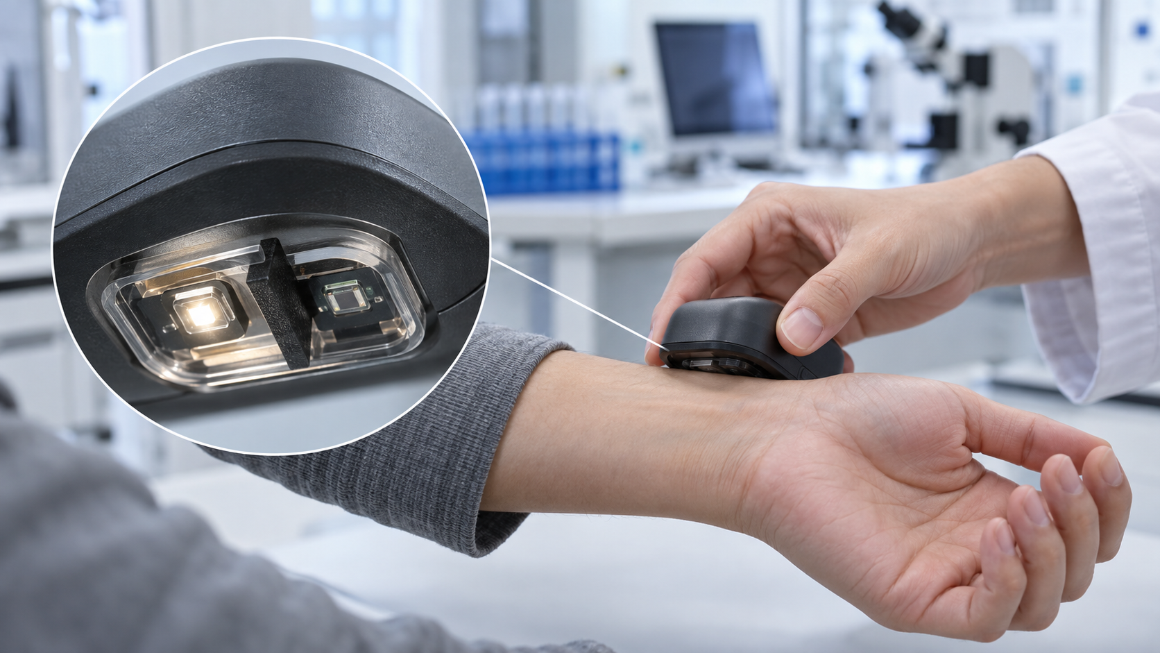
An absorbance reader for a test cartridge, a chip that reads fluorescence, a PPG sensor on a finger or wrist, a fluorescence sensor placed under the skin: in every light-based biosensor, the last component is a photodiode that turns light into current. From a materials engineer's point of view, this article covers the range of light silicon can detect, how dark current and noise set the floor of detection, and how ambient light is rejected. It then turns to the resins, windows, filters and skin interface in the light path.
- What a photodiode is (the short version)
- Types of light detector: pn, PIN, APD and SiPM
- Which light can be detected: the range set by the bandgap
- Dark current and noise set the floor of detection
- Turning current into voltage, and removing ambient light
- How they are used (as far as official documents and papers confirm)
- A materials engineer's view (1): the materials in the light path (windows, encapsulant, filters, black resin)
- A materials engineer's view (2): the optical interface with skin, and fouling of the window
- What standards and regulatory reviews confirm
- What is still hard, and what could not be confirmed
- Glossary / References / Claim-to-source audit
Sourced = stated in a published source (link given)
Our calculation = a value this article calculated from stated assumptions
Not yet confirmed = something for which no source could be confirmed
Interpretation of material design is marked "Commentary", and views with weaker support are marked Inference. A manufacturer's figure is called a "manufacturer's stated value" and comes with its grade and conditions.
This article explains the principles, materials, evaluation and regulation of light detectors. It is not advice on diagnosis, treatment or medication, or on how to take a measured value, and it does not rank any product or company.
1. What a photodiode is (the short version)
- What it does: when light with more energy than the bandgap strikes a semiconductor pn junction, electron-hole pairs are created and can be drawn off as a current proportional to the amount of light. Hamamatsu Photonics describes a photodiode as a device that produces a current or voltage when light hits it, and says the term usually means a sensor that accurately detects changes in light level Sourced [Reference 1].
- What is hard: the light a biosensor measures is weak, and the change to be measured is a small ripple on a large background. The pulsatile part (AC) of a PPG signal at the wrist is quoted as roughly 0.02% to 2% of the constant part (DC) Sourced [Reference 6]. The dark current and noise of the device, the amplifier, ambient light and the materials in the light path all bear on the floor of detection.
- Seen as materials: the window, the encapsulating resin, the filter, the black resin barrier and the interface with skin in front of the device set the amount and quality of the light that arrives. In many cases the materials around the device change performance more than the device itself (Commentary).
Photodetectors for optical communications, such as InGaAs and Ge on Si, including 200 Gbps-class high-speed devices, crystal quality and dark current, are covered in detail in our explainer on photodetectors (Optical Communications and Photonics). This article stays with low-speed, weak-light detection for biosensors and does not repeat the optical-communications material. The principle of PPG and differences by skin tone are in our explainer on wearable biosensors; the optics of surface plasmon resonance in our explainer on SPR; Raman spectroscopy in our explainer on Raman and SERS; fluorescence-based implantable sensors in our explainer on implantable sensors; and the use of a smartphone camera as a detector in our explainer on smartphone integration and digital twins. Here the focus is the light detector and the materials around it.
2. Types of light detector: pn, PIN, APD and SiPM
The light detectors a biosensor meets fall into four groups. They differ in how much the signal is amplified inside the device and how fast it responds.
| Type | How it works (as the sources describe it) | Strength | Points to watch |
|---|---|---|---|
| pn photodiode (Si) | Converts light to current at the junction of a p layer and an n layer. Linearity is above nine orders of magnitude for incident light from 10-12 to 10-2 W (depending on the device type and circuit) [Reference 1] | Output proportional to light. Low noise, small, rugged | No internal gain. For weak light, the limit is set by the amplifier circuit and its noise |
| PIN photodiode | A structure in which a reverse voltage widens the depletion layer, lowering capacitance and speeding carrier transit. Suited to fast response and used in optical communications and optical disks [Reference 1]. In a design note on wrist PPG, Si PIN devices are named as having the largest responsivity in the visible to near-infrared [Reference 6] | Fast response. High sensitivity | Reverse voltage widens the linear range but increases dark current and noise [Reference 1] |
| APD (avalanche) | Carriers accelerated by a strong reverse voltage create new electron-hole pairs ("avalanche multiplication"), raising the photocurrent inside the device [Reference 2] (the source describes InGaAs APDs) | With weak light, the following stage's noise becomes relatively smaller | Fluctuation in multiplication adds "excess noise". Gain varies with temperature, so voltage and temperature must be managed [Reference 2] |
| SiPM (MPPC) | Many Geiger-mode APD pixels, each with a series quenching resistor. Even a single photon gives a large output, so photons can be counted [Reference 3] | Detecting extremely weak fluorescence. The source lists detection of faint fluorescence from reagents as an application | Dark counts, afterpulses, crosstalk and pixel saturation. Gain varies with temperature, so the voltage is matched to the temperature or the device temperature is held constant [Reference 3] |
All Sourced (Hamamatsu Photonics technical documents; statements by the manufacturer. We did not check a separate document for Si APDs). For the MPPC, the source plots the relation between reverse voltage and temperature needed to hold a gain of about 1.7×10⁶ for one example (S13360-3050CS) [Reference 3] (not a value for every product).
Many biosensors need no more than a pn or PIN Si photodiode, because absorbance measurements and PPG involve light that changes slowly, over milliseconds to seconds. APDs and SiPMs appear where photons are few, as in fluorescence and chemiluminescence (our grouping).
3. Which light can be detected: the range set by the bandgap
A semiconductor cannot absorb light with less energy than its bandgap. Hamamatsu Photonics gives the cutoff wavelength as λc = 1240 ÷ Eg (nm, with Eg in eV) and states that silicon at room temperature has Eg = 1.12 eV, so the cutoff is 1100 nm Sourced [Reference 1]. On the short-wavelength side, light is absorbed in the surface diffusion layer, so the cutoff is 320 nm for ordinary Si and 190 nm for UV-enhanced types [Reference 1].
- Visible to near-infrared (green, red and near-infrared LEDs): the light used in PPG and pulse oximetry falls where silicon is strong. Pulse oximetry is described as based on PPG at two wavelengths, generally red and infrared Sourced [Reference 7].
- The near-infrared edge: silicon absorbs near-infrared light weakly and sensitivity falls. Using a thicker wafer to compensate calls for a higher voltage, increases dark current and slows the response, the source explains [Reference 1].
- Light beyond 1100 nm: Si cannot detect it, so other materials such as InGaAs are used. The standard InGaAs type covers 0.9 to 1.7 µm and a long-wavelength type goes up to 2.6 µm Sourced [Reference 2]. In biology, near-infrared spectroscopy that uses water absorption bands is one example (our grouping).
From a materials viewpoint there is one more important point: the spectral range of the device is also cut by the window material. The same document states that windows of borosilicate glass and resin coating absorb light shorter than about 300 nm, so ultraviolet sensitivity is lost, and that quartz windows are used for light shorter than 300 nm Sourced [Reference 1]. Section 7 continues with the window.
4. Dark current and noise set the floor of detection
The Hamamatsu technical document gives the noise current of a Si photodiode as the root of the sum of squares of the thermal noise of the shunt resistance (Rsh) and the shot noise of the dark current and of the photocurrent. The expressions are √(4kTB÷Rsh) for thermal noise, √(2qIDB) for shot noise of the dark current and √(2qILB) for shot noise of the photocurrent (B is the noise bandwidth) Sourced [Reference 1]. The floor of detection is expressed as NEP (noise equivalent power) = noise current ÷ responsivity, the incident light that produces a current equal to the noise [Reference 1].
Using the expressions above with conditions we chose, we see where the noise is set Our calculation.
- Assumptions: temperature 298 K and responsivity S = 0.43 A/W (our assumption, close to a value for 100% quantum efficiency in the green). The resistance that converts current to voltage (shunt or feedback), R, is 10 MΩ, 1 GΩ or 100 GΩ, and the dark current is 1 pA or 100 pA (illustrative values). Amplifier noise is not included
- Thermal noise: √(4kT÷R) is about 40.6 fA/√Hz at 10 MΩ, about 4.1 fA/√Hz at 1 GΩ and about 0.41 fA/√Hz at 100 GΩ
- Shot noise of the dark current: √(2qID) is about 0.57 fA/√Hz at 1 pA and about 5.7 fA/√Hz at 100 pA
- Result (NEP): about 9.5 fW/√Hz at 1 GΩ with 1 pA dark current, and about 16 fW/√Hz at 1 GΩ with 100 pA. At 100 GΩ, about 1.6 fW/√Hz with 1 pA and about 13 fW/√Hz with 100 pA. At 10 MΩ, about 94 to 95 fW/√Hz regardless of dark current
- When the photocurrent is large: the photocurrent at which its shot noise equals the thermal noise is 2kT÷(qR) ≈ 0.051 V ÷ R, about 51 pA for R = 1 GΩ. Above this, the fluctuation of the light itself (shot noise) dominates (the source says the same in terms of "IL well above 0.026÷Rsh" [Reference 1])
Assumptions and limits: temperature, responsivity, resistance and dark current are all illustrative values we chose, not the specification of any device. A real circuit adds amplifier voltage noise, input bias current and leakage current on the board. What the calculation shows is only the structure: raising the resistance lowers thermal noise, and the shot noise of the dark current then sets the floor (Commentary).
The same document describes other practical matters. A reverse voltage widens the linear range but increases dark current and noise [Reference 1]. If the feedback resistance is made larger than the shunt resistance, the amplifier's voltage noise and offset are multiplied and appear in the output [Reference 1]. Leakage current on the circuit board can exceed the amplifier's bias current, and guard rings and careful insulation are called for Sourced [Reference 1]. The InGaAs document states that dark current rises exponentially with temperature and offers cooled types [Reference 2].
5. Turning current into voltage, and removing ambient light
The transimpedance amplifier (current to voltage)
The output of a photodiode is a current. The standard circuit that converts it to voltage is the transimpedance amplifier (TIA), built on an operational amplifier with a feedback resistor Rf, giving Vout = −Isc × Rf. Because of the negative feedback, the load resistance seen by the photodiode is Rf ÷ A (A is the open-loop gain), which is extremely small, so the short-circuit current is measured almost ideally Sourced [Reference 1]. Rf cannot be made arbitrarily large, however: if Rf exceeds the shunt resistance Rsh, the amplifier's input voltage noise and offset are multiplied by (1 + Rf ÷ Rsh) and appear in the output. With input capacitance present, a feedback capacitance Cf prevents oscillation, and Rf and Cf together form a low-pass filter [Reference 1]. A Texas Instruments application report states that in high-resolution detection circuits that use photodiodes, bandwidth, gain and input-referred noise are coupled Sourced [Reference 5].
How ambient light is removed: time-division and subtraction, and modulation
The documentation of an analog front end for pulse oximeters (the AFE4400, document revised July 2014) explains that the photodiode signal has three components Sourced [Reference 4].
- Pulsatile component (AC): from the change in arterial blood volume.
- Constant component (DC, the "pleth" signal): light returned from time-invariant tissue and other parts of the path.
- Ambient light: outside light entering the photodiode.
The AC is a small fraction of the DC (the perfusion index), and the usable amplification is set by the size of the DC [Reference 4]. The circuit in this document turns two LEDs on in turn for short periods, reads the receiver while the LEDs are off, and so estimates the ambient light alone. After the ADC, it outputs "(LED on) − (ambient)" digitally, and it cancels the ambient-light DC offset with a current DAC before amplifying [Reference 4].
Lock-in detection takes this idea further, to a very narrow frequency band. A Stanford Research Systems technical note explains that a lock-in amplifier uses phase-sensitive detection to pick out only the component at a reference frequency and reject noise at other frequencies, and it gives an optical chopper or an oscillator as examples of fixed-frequency excitation Sourced [Reference 22]. For an optical biosensor, this means flashing the source at a fixed frequency and detecting only that frequency at the receiver (our grouping; we did not check the method of any individual product). Outside light (sunlight, room lighting) arrives as nearly constant light or as fluctuation at the mains frequency, so putting a "mark" on the source makes it easier to separate afterwards (Commentary).
We apply the Section 4 expression to a PPG signal Our calculation.
- Assumptions: a constant (DC) current of 1 µA through the photodiode (our assumption) and a signal bandwidth of 10 Hz (our assumption). The pulsatile fraction is 0.02% (weak pulse) or 2% (strong pulse), the wrist values quoted [Reference 6]
- Shot noise of the photocurrent: √(2q × 1 µA × 10 Hz) ≈ 1.8 pA
- Pulsatile component: 0.2 nA (200 pA) at 0.02%, 20 nA at 2%
- Ratio: 200 pA ÷ 1.8 pA ≈ 110 (0.02%), and 20 nA ÷ 1.8 pA ≈ 11,000 (2%)
Assumptions and limits: the 1 µA DC and the 10 Hz bandwidth are values we chose. Amplifier noise, motion, ambient light and variation in skin contact are not included. What the calculation shows is that if only the fluctuation in photon number mattered, even a weak pulse could be seen. A reading that follows is that the real difficulty of PPG lies less in device noise than in external disturbances: motion, ambient light, contact and the optical properties of skin (Commentary; for the noise sources the sources list, see our explainer on wearable biosensors).
6. How they are used (as far as official documents and papers confirm)
| Use | Role of the detector | What primary sources confirm | Notes (what could not be confirmed) |
|---|---|---|---|
| Absorbance measurement (cartridges, microcuvettes) | Receives light that has passed through the sample (transmitted and scattered) and finds concentration from the absorbance | HemoCue Hb 801 System: FDA 510(k) K181751 (Hemocue AB, decision date 1 February 2019, product code GKR, Class II under 21 CFR 864.5620). About 10 µL of whole blood is drawn into a microcuvette, and the analyzer measures the absorbance of whole blood at the isosbestic point of hemoglobin and oxyhemoglobin and converts it to a concentration by an algorithm. It is traceable to the international reference method, HiCN. The use is quantitative determination of hemoglobin in whole blood at the point of care, for professional in vitro diagnostic use only [Reference 14, 15] | The summary of the review does not state the type of light detector. We do not cover performance figures (accuracy) |
| Fluorescence detection (on a chip) | Blocks the excitation light and receives only the fluorescence. Reads weak light with a device integrated into the chip | Pereira et al. (2011): a thin-film amorphous silicon (a-Si:H) photodiode on a glass substrate, with an amorphous silicon-carbon film deposited directly on top as a fluorescence filter, integrated with a PDMS microfluidic network. In a model immunoassay using a quantum-dot-labeled antibody, the total assay time was 30 minutes, and results were reported to depend linearly on antibody concentration in the nanomolar to micromolar range, consistent with fluorescence microscopy [Reference 9]. Dattner and Yadid-Pecht (2010): a CMOS contact imager with an integrated absorption-type emission filter (20 µm thick) of poly-acrylic acid containing an absorbing dye, tested with fluorescent polystyrene microspheres [Reference 10] | Both are research reports on model systems, not performance on real specimens or in products |
| Extremely weak fluorescence | Counts photons (SiPM / MPPC) | The Hamamatsu document lists detection of faint fluorescence from reagents as an application of the MPPC [Reference 3] | We did not confirm use in a biosensor product, nor an individual paper or review document on reading chemiluminescence with a photodetector |
| PPG and pulse oximetry | Receives LED light returned after absorption and scattering in tissue. Oxygen saturation is estimated from the pulsation of PPG at two wavelengths, red and infrared [Reference 7] | 21 CFR 870.2700: an oximeter transmits radiation at a known wavelength through blood and measures oxygen saturation from the reflected or scattered radiation; Class II [Reference 16]. The standard is ISO 80601-2-61:2026 (3rd edition, April 2026) [Reference 17]. Nitzan et al. (2014) summarize that calibration is empirical for each sensor type, that manufacturers state an accuracy of 2% (evaluated as SD), and that low perfusion and motion are limits [Reference 7]. On 7 January 2025 the FDA issued draft guidance on performance testing and labeling of medical pulse oximeters, citing concerns that include skin pigmentation [Reference 18] | Whether the draft was later finalized could not be confirmed. Differences by skin tone are in our explainer on wearable biosensors |
| Fluorescence sensor placed under the skin | Receives the indicator's fluorescence (electro-optical circuitry handles excitation and detection) | Eversense: FDA PMA P160048 (Senseonics, approved 21 June 2018). The review document says the sensor uses a fluorescence sensing mechanism to measure glucose in interstitial fluid every 5 minutes, and lists among its tests the function of electro-optical circuitry that excites the fluorescent indicator and detects its emitted fluorescence [Reference 19] | The review document does not state the type of light detector. For the structure, see our explainer on implantable sensors |
| Surface plasmon resonance (SPR) | Reads the shift in the angle or wavelength of reflected light | The optics are covered in our explainer on SPR. Photodiodes or image sensors do the detection | We do not cover specifications of individual detectors |
All Sourced (regulatory documents, peer-reviewed papers and the official pages of standards bodies). Clearance or authorization is a judgment for a specific intended use. FDA 510(k) clearance, De Novo authorization and PMA approval are separate systems. Product names are given as they appear in FDA documents and do not rank them.
How this differs from a smartphone camera (image sensor)
Using a smartphone camera as a detector is covered in detail in our explainer on smartphone integration and digital twins. Seen from the detector side, there are these differences (Commentary; we did not check individual sources).
- One element or many pixels: a photodiode turns the light on one (or a few) receiving areas directly into current. An image sensor arranges many small photodiodes to obtain information by position. Hamamatsu likewise describes multi-element photodiode arrays for position detection and spectroscopy [Reference 1].
- What is part of the measurement system: with a dedicated detector circuit, the person measuring sets the gain, the integration time and the source timing. With a camera, exposure, white balance and image processing can be part of the measurement system, and reproducibility depends on the settings.
- Choosing between them: an image sensor suits a distribution of color or position, while a dedicated detector, including cooling or amplification, suits precise tracking of faint light. For fluorescence detection there are studies using a CMOS contact imager [Reference 10] and studies using a photodiode [Reference 9].
7. A materials engineer's view (1): the materials in the light path (windows, encapsulant, filters, black resin)
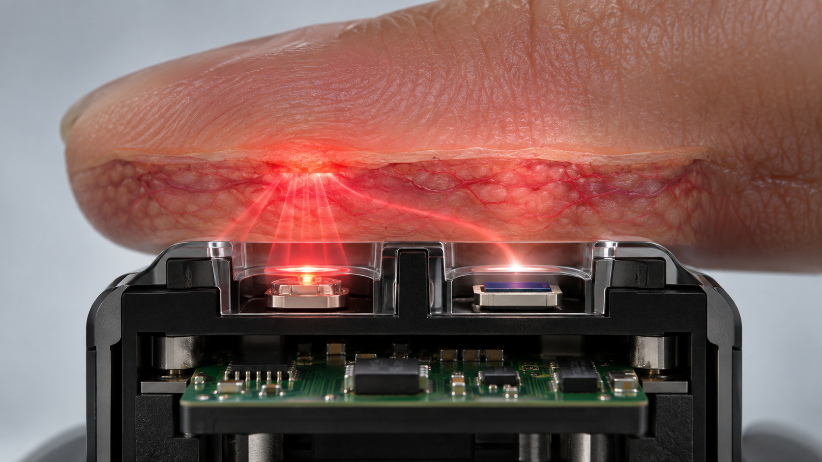
The performance of an optical sensor is set not only by the detector but by the stack of materials in front of it. An Analog Devices technical article (design guidance for wrist PPG from Maxim Integrated, 26 March 2019) shows a configuration in which the LEDs and the photodiode are encapsulated in a transparent material that serves as a moisture barrier and as the interface between the optical parts and the wrist, with light-absorbing barriers between the LEDs and the photodetector Sourced [Reference 6].
View the original SVG schematic, source notes and numerical details
| Part | What sources confirm | Points for materials engineers (Commentary) |
|---|---|---|
| Window (glass, resin) | Windows of borosilicate glass and resin coating absorb light shorter than about 300 nm and lose ultraviolet sensitivity; quartz windows are used for light shorter than 300 nm [Reference 1] | The window cuts the spectral range of the device. Where ultraviolet fluorescence or excitation is used, the choice of window material comes first. For matching refractive index between glass and adhesive, see our explainer on UV bonding of glass; for refractive index and the evaluation of yellowing in clear resins, our explainer on clear UV-curable resins |
| Encapsulant (transparent) | Serves as moisture barrier and optical interface. A refractive index close to skin (about 1.4) reduces reflection loss at the interface, and softness raises contact area and pressure with skin. Silicones are commonly used [Reference 6]. The article's table gives stated values for Dow Corning silicones: for example, Sylgard 184 has a refractive index of 1.4118 (589 nm) and a transmission of 97% (532 nm) and 96% (880 nm) at 3.2 mm thickness [Reference 6] | Transmittance from green to near-infrared, refractive index and hardness become selection items for the encapsulant. For the basics of silicones, see our explainer on silicones. A manufacturer's stated value comes with thickness, wavelength and test conditions, so values are not a like-for-like comparison |
| Ageing of the encapsulant | A Dow Corning (as it then was) brochure for LED silicones shows OE-6630 as more stable than epoxy in transmittance after UV irradiation (365 nm, 19 mW/cm², 4 hours), and several silicones with less than 5% drop in transmittance at 400 nm after 1,000 hours at 150 °C in air (1 mm thickness). The comparison is with "typical optical grade epoxy", with no composition given [Reference 13] (manufacturer's stated values). Epoxy absorbs moisture and swells, and moisture-induced swelling stress can cause failure in non-hermetic optoelectronic packages [Reference 12] | One can read that yellowing generally removes transmittance from short wavelengths (blue to green) first (Inference; we did not check an individual source). PPG with a green LED, and blue-to-green fluorescence, may be affected more than the near-infrared. Water uptake and permeability to water vapor are separate properties (see our explainer on silicones) |
| Optical filter | An a-SiC film deposited directly on the photodetector to block excitation light and pass fluorescence [Reference 9]; a 20 µm absorption-type filter of dye in poly-acrylic acid, designed with the Beer-Lambert law [Reference 10]. Photodiodes with a visual-sensitivity compensation filter also exist [Reference 1] | For dye-in-resin, the issues are fading and leaching of the dye, uniformity of thickness, and the refractive index of the adhesive used to attach it. A thin film can be made together with the device, but the process then matches the device's. An interference coating is known to shift its passband with the angle of incidence (general optics; we did not check an individual source) |
| Black resin barrier | A light barrier between LED and detector suppresses crosstalk, light that has not passed through skin. High crosstalk drowns the pulsation and PPG cannot be measured [Reference 6] | Whether a resin that looks black absorbs at the wavelength in use, especially in the near-infrared, is a separate question that needs checking (closer to Inference, a general point). For black encapsulating resins, see our explainer on semiconductor encapsulants. Around the device, the design uses materials that pass light and materials that block it, side by side |
The left two columns are Sourced (each source; Dow Corning values are via the Analog Devices article, as the manufacturer's stated values). The right column is this article's "Commentary", and where we wrote Inference the view has weak support.
For optical detection in microfluidic chips, a review (Mogensen and Kutter, 2009) likewise says that interest has grown in low-cost solutions made of polymer materials that are easy to mass-produce Sourced [Reference 11]. For the relation between the chip's resin (channel or window) and the detector, see our explainer on lab-on-a-chip.
Around an optical sensor, transparent resin (window, encapsulant) and black resin (barrier) sit side by side: materials with opposite optical properties.
- Transparent side: transmittance at the wavelength in use, refractive index (matching skin and the device), yellowing over time, and water uptake. As in Section 3, the range the device can detect is also cut by the window [Reference 1]
- Black side: whether the barrier absorbs stray light [Reference 6]. If absorption is weak, light travelling inside the resin reaches the detector directly
- Interfaces: bonding of the two resins, and adhesion between device and resin. Swelling from moisture becomes stress on the interface [Reference 12]
Index matching of adhesives, water uptake and transmission of silicones, and the fillers of black resins: knowledge from the adhesives and encapsulants explainers in this series (clear UV-curable resins, UV bonding of glass, semiconductor encapsulants, silicones) applies directly here (Commentary).
8. A materials engineer's view (2): the optical interface with skin, and fouling of the window
Pressure and contact
Teng and Zhang (2004) varied the contact force from 0.2 to 1.8 N on a reflective PPG sensor on the fingers of 15 healthy subjects. As contact force increased, the DC component increased and the normalized pulse area decreased. The pulse amplitude and AC/DC first rose and then fell; the force at the peak varied by person from 0.2 to 1.0 N, and most subjects reached maximum amplitude at 0.2 to 0.4 N Sourced [Reference 8]. The authors conclude that the effect of contact force should be examined carefully in designing PPG-based devices. This is a result for fingertips, a small group and a reflective sensor, not a value for the wrist or other sites. What it suggests is that the hardness and shape (a raised profile) of the window and the tightness of the band are design variables that move the size of the signal itself (Commentary). The Analog Devices article likewise describes an assembly that protrudes from the underside of the band to ensure tight skin contact, and an encapsulant with some "give" that follows the skin [Reference 6].
We use the normal-incidence reflectance R = ((n₁−n₂)÷(n₁+n₂))² (the same expression as in our explainer on clear UV-curable resins) Our calculation.
- Assumptions: an encapsulant refractive index of 1.41 (close to the stated 1.4118 of Sylgard 184 [Reference 6]), 1.40 for the outermost skin layers (stratum corneum, epidermis; the value in the seven-layer model cited in the Analog Devices article [Reference 6]), and 1.0 for air. Absorption and multiple reflections are ignored
- In contact: the difference between resin and skin is 0.01. R ≈ (0.01÷2.81)² ≈ 0.0013%
- With an air gap: R ≈ 2.9% from resin to air and R ≈ 2.8% from air to skin. One-way transmission is about 0.971 × 0.972 ≈ 0.944 (about 5.6% lost). Light crosses twice, out and back, so about 0.944² ≈ 0.89 (about 11% lost)
Assumptions and limits: the refractive indices are illustrative; real skin is rough, and sweat or sebum can fill the gap. What the calculation gives is a sense of scale: interface reflection alone can lose around a tenth of the light. It is not a prediction of real signal loss (Commentary).
Fouling of the window
Sweat, sebum and proteins settle on a window that touches the body. For implants, Ward's review organizes the sequence from adsorption of proteins such as fibrinogen on the surface right after implantation (biofouling) to macrophage binding and formation of a fibrous capsule Sourced [Reference 20]. The capsule becomes impermeable or hypopermeable to many compounds [Reference 20]. The foreign-body response around fluorescence-based implantable sensors is covered in our explainer on implantable sensors.
We could not confirm any primary source that quantifies, under the same conditions, how much fouling of an optical window changes the received light or the fluorescence signal Not yet confirmed. It is reasonable to expect that the surface energy, roughness and coating (antifouling) of the window change how it fouls (Inference). Materials that touch skin or body fluid are evaluated within a risk-management process under the biological evaluation framework ISO 10993-1:2025 (6th edition) [Reference 21]. Windows and encapsulants can be among the parts concerned (Commentary; application depends on the product and use).
9. What standards and regulatory reviews confirm
- Pulse oximeters: the oximeter of 21 CFR 870.2700 is Class II [Reference 16]. The standard for basic safety and essential performance is ISO 80601-2-61:2026 (3rd edition); it covers the probe and monitor and excludes laboratory research use and oximeters that need a blood sample [Reference 17]. In January 2025 the FDA issued draft recommendations for medical pulse oximeters that include the effect of skin tone [Reference 18].
- In vitro diagnostic absorbance instruments: the HemoCue Hb 801 was found substantially equivalent by 510(k) (K181751, 1 February 2019) as a Class II automated hemoglobin system [Reference 14, 15].
- Fluorescence-based sensors placed in the body: Eversense is a PMA (P160048, approved 21 June 2018) [Reference 19]. 510(k), De Novo and PMA are separate systems, and clearance or approval is a judgment for a specific intended use.
- The detector itself: the summaries of review documents we examined did not state the type or specification of the light detector. It reads as a design decision made for the purpose of the device and evaluated through the performance of the whole device (Commentary).
10. What is still hard, and what could not be confirmed
(1) Long-term optical stability of encapsulants and windows
The values in the Dow Corning document are a manufacturer's comparison, with no composition given for the epoxy side [Reference 13]. We could not confirm a public primary source that compares transmittance and yellowing of several encapsulants under the same conditions. Not yet confirmed
(2) Quantifying fouling of optical windows
As in Section 8, we found no source that quantifies how much fouling of a window changes the signal. Not yet confirmed
(3) Use of detectors for very weak light
SiPMs (MPPCs) list fluorescence detection as an application [Reference 3], but we did not confirm use in a biosensor product, nor an individual source on reading chemiluminescence with a photodetector. Not yet confirmed
(4) The detector cannot be identified from the review documents
Neither the 510(k) summary of the HemoCue Hb 801 nor the review document of Eversense states the type of light detector [Reference 14, 19]. We cannot compare detector differences between products from public documents.
(5) Skin tone and pulse oximeters; the status of the draft
Differences by skin tone are covered in our explainer on wearable biosensors. We could not confirm whether the FDA's draft guidance of January 2025 has since been finalized [Reference 18].
(6) How to take measured values
This article does not cover how to take a measured value, oxygen saturation or pulse rate, nor reference values. The FDA's page on pulse oximeters also says to contact a health care provider if one is concerned about a reading [Reference 18].
- A Si photodiode can detect up to about 1100 nm (manufacturer's stated value: Eg 1.12 eV, cutoff 1100 nm). Longer light needs other materials such as InGaAs Sourced
- The floor of detection is set by thermal noise and the shot noise of the dark current. Under illustrative conditions, a larger resistance lowers thermal noise and the dark current then sets the floor Our calculation
- Ambient light is removed by time-division lighting of LEDs with subtraction of the reading while off, or by lock-in detection. Sourced
- The materials in the light path move performance. The window cuts the spectral range, the encapsulant sets transmittance, refractive index, yellowing and water uptake, the black barrier sets stray light, and the interface with skin sets reflection and contact (Commentary)
- Contact force moves the size of the signal. In an example with 15 fingertips, AC and AC/DC rose and fell with contact force Sourced
- Review documents do not state the type of light detector. Public quantitative sources on fouling of windows and long-term optical stability of encapsulants could not be confirmed
11. Glossary
- Photodiode
- A device in which light striking a semiconductor junction produces a current (or voltage). Used to measure light.
- PIN photodiode
- A structure that widens the depletion layer with reverse voltage, lowering capacitance and speeding the response.
- APD
- Avalanche photodiode. A device that multiplies current internally. Fluctuation in multiplication adds excess noise.
- SiPM / MPPC
- A device with many Geiger-mode APD pixels, able to count photons.
- Bandgap
- The energy needed to lift an electron from the valence band to the conduction band. Sets the long-wavelength limit of detectable light.
- Responsivity (A/W)
- Current obtained per unit of incident optical power. Set by quantum efficiency and wavelength.
- Dark current
- Current that flows with no light. Increases with temperature and reverse voltage.
- Shot noise / thermal noise
- Current fluctuation from charge being discrete / from the thermal motion in a resistor.
- NEP (noise equivalent power)
- The incident light that gives a signal equal to the noise. The smaller, the fainter the light that can be detected.
- TIA
- Transimpedance amplifier. An amplifier circuit that converts current to voltage.
- Lock-in detection
- Detection that extracts only the component at a reference frequency. The source is flashed and the receiver reads only that frequency.
- Perfusion index (PI)
- The ratio of the pulsatile (AC) to the constant (DC) component of PPG.
- Crosstalk
- Light that reaches the detector without taking the path to be measured. Suppressed by a barrier.
- Biofouling
- Adsorption of proteins and similar material on a surface in contact with body fluid or skin.
- Isosbestic point
- A wavelength at which two chemical species absorb equally.
12. References
- Hamamatsu Photonics Technical note "Si photodiodes" (Cat. No. KSPD9001E04, December 2025, PDF) — www.hamamatsu.com
- Hamamatsu Photonics Technical document "Compound semiconductor photodetectors" (in Japanese; Cat. No. KIRD9004J04, December 2025, PDF) — www.hamamatsu.com
- Hamamatsu Photonics Technical note "MPPC" (Cat. No. KAPD9008E04, February 2025, PDF) — www.hamamatsu.com
- Texas Instruments AFE4400 data sheet "Integrated Analog Front-End for Heart Rate Monitors and Low-Cost Pulse Oximeters" (SBAS601H, December 2012, revised July 2014) — www.ti.com
- Texas Instruments Ramus X. "Transimpedance Considerations for High-Speed Amplifiers", Application Report SBOA122, November 2009 — www.ti.com
- Analog Devices "Guidelines to Enhancing the Heart-Rate Monitoring Performance of Biosensing Wearables", technical article, 26 March 2019 — www.analog.com
- Nitzan M et al. "Pulse oximetry: fundamentals and technology update", Med Devices (Auckl) 2014;7:231 — doi.org
- Teng XF, Zhang YT. "The effect of contacting force on photoplethysmographic signals", Physiol Meas 2004;25:1323-1335 — doi.org
- Pereira DY et al. "Heterogeneous immunoassays in microfluidic format using fluorescence detection with integrated amorphous silicon photodiodes", Biomicrofluidics 2011;5:014102 — doi.org
- Dattner Y, Yadid-Pecht O. "Low light CMOS contact imager with an integrated poly-acrylic emission filter for fluorescence detection", Sensors 2010;10:5014-5027 — doi.org
- Mogensen KB, Kutter JP. "Optical detection in microfluidic systems", Electrophoresis 2009;30(Suppl 1) — doi.org
- Madduri A et al. "An experimental and computational study on moisture induced epoxy swelling in non-hermetic optoelectronic packages", J Electron Packag 2012;134:011007 — doi.org
- Dow Corning "LED Packaging: Advanced silicone technology for LED applications", brochure (no date given; PDF distributed by a distributor) — prod.ellsworth.com
- FDA 510(k) K181751 "HemoCue Hb 801 System", 510(k) Summary (PDF) — www.accessdata.fda.gov
- U.S. Code of Federal Regulations 21 CFR 864.5620 Automated hemoglobin system — www.ecfr.gov
- U.S. Code of Federal Regulations 21 CFR 870.2700 Oximeter — www.ecfr.gov
- ISO ISO 80601-2-61:2026 Medical electrical equipment — Part 2-61: Particular requirements for basic safety and essential performance of pulse oximeter equipment (3rd edition, April 2026) — www.iso.org
- FDA "Pulse Oximeters", information page (content current as of 6 January 2025) — www.fda.gov
- FDA PMA P160048 (Eversense CGM System), Summary of Safety and Effectiveness Data (PDF) — www.accessdata.fda.gov
- Ward WK. "A review of the foreign-body response to subcutaneously-implanted devices: the role of macrophages and cytokines in biofouling and fibrosis", J Diabetes Sci Technol 2008;2:768-777 — doi.org
- ISO ISO 10993-1:2025 Biological evaluation of medical devices — Part 1: Requirements and general principles for the evaluation of biological safety within a risk management process (6th edition) — www.iso.org
- Stanford Research Systems Tech Note "Lock-In Amplifier Basics", 7 April 2020 (PDF) — www.thinksrs.com
13. Claim-to-source audit
| Claim in the text | Basis | Label |
|---|---|---|
| The principle of the Si photodiode (light on a junction produces current); Eg = 1.12 eV and a 1100 nm cutoff (λc = 1240÷Eg); short-wavelength cutoffs of 320 nm (ordinary) and 190 nm (UV-enhanced); borosilicate glass and resin-coated windows absorbing below about 300 nm and quartz windows being used; falling near-infrared sensitivity, and a thicker wafer bringing higher voltage, more dark current and slower response | Hamamatsu Photonics technical note "Si photodiodes"[Reference 1] https://www.hamamatsu.com/content/dam/hamamatsu-photonics/sites/documents/99_SALES_LIBRARY/ssd/si_pd_kspd9001e.pdf | Sourced |
| The noise current of a Si photodiode (thermal noise √(4kTB÷Rsh), shot noise of dark current and photocurrent); NEP = noise current ÷ responsivity; shot noise dominating when the photocurrent is well above 0.026÷Rsh; reverse voltage widening linearity but increasing dark current and noise; linearity above nine orders for 10-12 to 10-2 W; the relation of feedback and shunt resistance; board leakage current; features of the PIN; uses of photodiode arrays; devices with a visual-sensitivity compensation filter | Same document (technical note "Si photodiodes", Cat. No. KSPD9001E04)[Reference 1] https://www.hamamatsu.com/content/dam/hamamatsu-photonics/sites/documents/99_SALES_LIBRARY/ssd/si_pd_kspd9001e.pdf | Sourced |
| Spectral ranges of InGaAs (short-wavelength 0.5 to 1.7 µm, standard 0.9 to 1.7 µm, long-wavelength to 2.6 µm); avalanche multiplication in APDs; excess noise; temperature dependence of gain; InGaAs dark current rising exponentially with temperature and the availability of cooled types | Hamamatsu Photonics technical document "Compound semiconductor photodetectors" (in Japanese)[Reference 2] https://www.hamamatsu.com/content/dam/hamamatsu-photonics/sites/documents/99_SALES_LIBRARY/ssd/compound_kird9004j.pdf | Sourced |
| That the MPPC (SiPM) consists of Geiger-mode APD pixels with quenching resistors and can count photons; that gain varies with temperature (the relation of voltage and temperature to hold a gain of about 1.7×10⁶ for S13360-3050CS); that pixel saturation reduces linearity; that detecting faint fluorescence of reagents is an application | Hamamatsu Photonics technical note "MPPC"[Reference 3] https://www.hamamatsu.com/content/dam/hamamatsu-photonics/sites/documents/99_SALES_LIBRARY/ssd/mppc_kapd9008e.pdf | Sourced |
| The three components of the PPG signal (AC, DC, ambient light); programmable TIA feedback resistance and capacitance; lighting LEDs in turn, estimating ambient light from the reading while they are off and subtracting it digitally after the ADC; cancelling the ambient-light DC offset with a current DAC before amplifying | Texas Instruments AFE4400 data sheet (SBAS601H, revised July 2014)[Reference 4] https://www.ti.com/lit/ds/symlink/afe4400.pdf | Sourced |
| That in high-resolution detection circuits using photodiodes, bandwidth, gain and input-referred noise are coupled | Texas Instruments Application Report SBOA122 (November 2009)[Reference 5] https://www.ti.com/lit/an/sboa122/sboa122.pdf | Sourced |
| That the pulsatile fraction (PI = AC÷DC) of wrist PPG is 0.02% (weak pulse) to 2% (strong pulse); that most PPG sensors use green LEDs near 530 nm; that Si PIN devices have large responsivity in the visible to near-infrared; that LEDs and photodiode are encapsulated in a transparent material serving as moisture barrier and interface; that a refractive index close to skin (about 1.4) reduces reflection loss; that a soft encapsulant raises contact area and pressure; that silicones are commonly used, with stated values for Sylgard 184 (refractive index 1.4118, transmission 97% at 532 nm and 96% at 880 nm, 3.2 mm thick); that light barriers suppress crosstalk; the refractive indices of the seven-layer skin model (stratum corneum and epidermis 1.40) | Analog Devices technical article (26 March 2019)[Reference 6] https://www.analog.com/en/resources/technical-articles/guidelines-to-enhancing-the-heartrate-monitoring-performance-of-biosensing-wearables.html | Sourced |
| That pulse oximetry is based on PPG at two wavelengths, red and infrared; that calibration is empirical for each sensor type; that the manufacturers' stated accuracy is 2% (evaluated as SD); that low perfusion and motion are limits | Abstract of Nitzan et al. (2014)[Reference 7] https://doi.org/10.2147/MDER.S47319 | Sourced |
| Contact force of 0.2 to 1.8 N on reflective PPG at the fingers of 15 healthy subjects: DC rising, normalized pulse area falling, AC and AC/DC first rising and then falling, with the peak at 0.2 to 1.0 N depending on the person and mostly at 0.2 to 0.4 N | Abstract of Teng and Zhang (2004)[Reference 8] https://doi.org/10.1088/0967-3334/25/5/020 | Sourced |
| A thin-film a-Si:H photodiode on glass, an a-SiC fluorescence filter deposited directly on it, a PDMS microfluidic network, and a model immunoassay with a quantum-dot-labeled antibody (30 minutes; linear in the nanomolar to micromolar range; consistent with fluorescence microscopy) | Abstract of Pereira et al. (2011)[Reference 9] https://doi.org/10.1063/1.3553014 | Sourced |
| Integration of an absorption-type emission filter (poly-acrylic acid with absorbing dye, 20 µm thick, designed with the Beer-Lambert law) into a CMOS contact imager, tested with fluorescent polystyrene microspheres | Abstract of Dattner and Yadid-Pecht (2010)[Reference 10] https://doi.org/10.3390/s100505014 | Sourced |
| That in optical detection in microfluidic systems, interest has grown in low-cost solutions in polymer materials (review) | Abstract of Mogensen and Kutter (2009)[Reference 11] https://doi.org/10.1002/elps.200900101 | Sourced |
| That epoxy absorbs moisture and swells, and that moisture-induced swelling stress can cause failure in non-hermetic optoelectronic packages | Abstract of Madduri et al. (2012)[Reference 12] https://doi.org/10.1115/1.4005911 | Sourced |
| OE-6630 being more stable than epoxy in transmittance after UV irradiation (365 nm, 19 mW/cm², 4 hours); several silicones showing less than 5% drop in transmittance at 400 nm after 1,000 hours at 150 °C in air (1 mm thick). The comparison is with "typical optical grade epoxy" | Dow Corning brochure (manufacturer's stated values; no date given)[Reference 13] https://prod.ellsworth.com/globalassets/literature-library/manufacturer/dow-corning/dow-corning-brochure-silicone-technology-for-led-packaging.pdf | Sourced |
| HemoCue Hb 801 System: 510(k) K181751, Hemocue AB, received 2 July 2018 and decided 1 February 2019, substantially equivalent, product code GKR, about 10 µL of whole blood, absorbance of whole blood at the isosbestic point (transmitted and scattered light), conversion to concentration by an algorithm, traceable to the HiCN method, quantitative determination of hemoglobin in whole blood at the point of care, for professional in vitro diagnostic use. That the summary does not state the type of light detector | FDA 510(k) Summary[Reference 14] https://www.accessdata.fda.gov/cdrh_docs/pdf18/K181751.pdf; 21 CFR 864.5620 (automated hemoglobin system, Class II)[Reference 15] https://www.ecfr.gov/current/title-21/section-864.5620 | Sourced |
| The identification of the oximeter in 21 CFR 870.2700 (radiation at a known wavelength passed through blood; saturation from the reflected or scattered amount) and Class II | U.S. Code of Federal Regulations[Reference 16] https://www.ecfr.gov/current/title-21/section-870.2700 | Sourced |
| That ISO 80601-2-61:2026 (3rd edition, April 2026) covers the basic safety and essential performance of pulse oximeter equipment and excludes laboratory research use and oximeters needing a blood sample | Official ISO page[Reference 17] https://www.iso.org/standard/84595.html | Sourced |
| That on 7 January 2025 the FDA issued draft guidance on performance testing and labeling of medical pulse oximeters, citing concerns that include skin pigmentation, and advises contacting a health care provider if one is concerned about a reading | FDA "Pulse Oximeters" page (as of 6 January 2025)[Reference 18] https://www.fda.gov/medical-devices/products-and-medical-procedures/pulse-oximeters | Sourced |
| Eversense: PMA P160048, approved 21 June 2018; a fluorescence sensing mechanism measuring glucose in interstitial fluid every 5 minutes; a test of electro-optical circuitry that excites the fluorescent indicator and detects its emitted fluorescence. That the review document does not state the type of light detector | FDA SSED[Reference 19] https://www.accessdata.fda.gov/cdrh_docs/pdf16/P160048B.pdf | Sourced |
| The sequence from protein adsorption on the surface after implantation (biofouling) to foreign-body response and fibrous capsule formation, and the capsule being impermeable or hypopermeable to many compounds | Abstract of Ward (2008)[Reference 20] https://doi.org/10.1177/193229680800200504 | Sourced |
| That ISO 10993-1:2025 (6th edition) is the framework for biological safety evaluation of medical devices within a risk-management process | Official ISO page[Reference 21] https://www.iso.org/standard/10993-1 | Sourced |
| That a lock-in amplifier uses phase-sensitive detection to extract only the component at a reference frequency and reject noise at other frequencies; an optical chopper and an oscillator as examples of excitation | Stanford Research Systems Tech Note (7 April 2020)[Reference 22] https://www.thinksrs.com/downloads/pdfs/applicationnotes/Lock-In%20Basics.pdf | Sourced |
| The noise and NEP values (thermal noise 40.6, 4.1 and 0.41 fA/√Hz; dark-current shot noise 0.57 and 5.7 fA/√Hz; NEP 94, 95, 9.5, 16, 1.6 and 13 fW/√Hz; crossover photocurrent ≈ 0.051 V÷R); the shot noise of the PPG photocurrent (about 1.8 pA at 1 µA and 10 Hz; a ratio to the pulsatile component of about 110 to about 11,000); the reflection loss from an air gap between window and skin (about 11%) | Our calculation (the expressions are from the Hamamatsu technical document and standard optics; temperature, responsivity, resistance, dark current, DC current, bandwidth and refractive indices are illustrative values we chose) | Our calculation |
| The choice of window material; yellowing and water uptake of the encapsulant; fading of the filter; absorption of the black resin in the near-infrared; fouling of the window; the choice of detector as a design decision; the differences from a smartphone camera; the grouping of when to use which detector | This article's own grouping and commentary of published content (including passages marked Inference) | Commentary |
| A like-for-like comparison of transmittance and yellowing of encapsulants and windows; quantification of signal change from fouling of optical windows; use of SiPMs in biosensor products or individual sources on chemiluminescence; the type of detector in HemoCue and Eversense; whether the FDA draft guidance was finalized | Could not be confirmed in the primary sources this article consulted | Not yet confirmed |
| That Figs. 1, 3 and 4 are explanatory drawings; that Fig. 2 includes our calculation; that the hero image is an AI-generated image | Note by this article | Commentary |
Last updated 4 October 2026. Sources are limited to primary material (manufacturers' technical documents, peer-reviewed papers, official FDA documents, U.S. regulations and the official pages of standards bodies). Interpretation of material design is marked Commentary and kept separate from sourced fact. Long-term optical stability of encapsulants and windows, quantification of fouling of optical windows, use of SiPMs in biosensor products, the type of detector stated in review documents, and whether the FDA draft guidance was finalized are not stated, because no primary source could be confirmed. A manufacturer's value is given as a manufacturer's stated value with its grade and conditions. For standards (ISO) only titles, editions and scope were confirmed, not the texts. The calculations use illustrative values to explain structure. This article does not cover how to take measured values.