TECHNOLOGY EXPLAINER
Alkaline Water Electrolysis
— nickel, KOH and a porous diaphragm: a method with no precious metals meets variable power
Alkaline water electrolysis splits water in a concentrated KOH (potassium hydroxide) solution, using nickel-based electrodes and a porous diaphragm. It uses no iridium or other precious metals, and equipment from megawatt scale to tens of megawatts has built up a track record. But at low current the hydrogen and oxygen mix more readily, and following variable renewable power takes work on both materials and control.
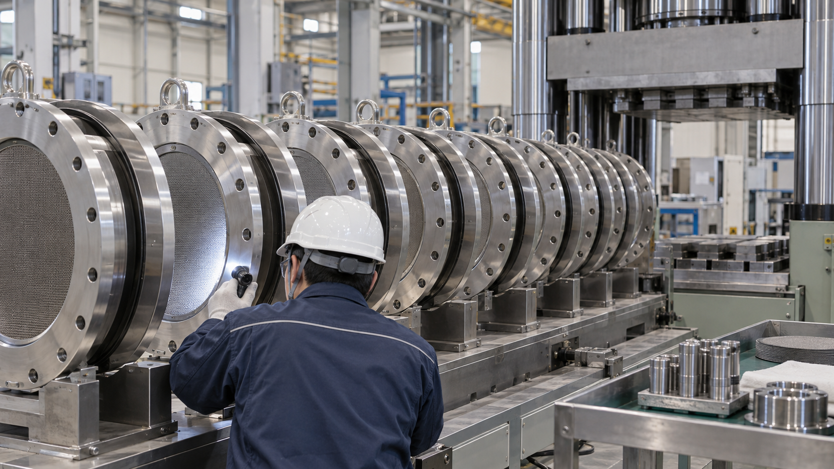
- What alkaline water electrolysis is (the short version)
- Reactions and cell structure — the zero-gap cell
- A materials engineer’s view (1): electrolyte and diaphragm — passing ions but not gas in strong KOH
- Electrodes — nickel at the core, no precious metals
- Following variable power — what happens at low current density
- A materials engineer’s view (2): every shutdown damages the electrodes — reverse current
- Scale-up so far — separating demonstration, commercial and plan
- Our calculation: back-calculating the current density at FH2R
- Reading the numbers, evaluation and standards
- Challenges and limits / Glossary / Primary sources / Claim-to-source audit
Sourced = a value or statement in published material (link given)
Our calculation = a figure this article derived, with the assumptions spelled out
Not yet confirmed = a plan or target with no confirmed result
Structural readings and materials-design interpretations are marked separately as Commentary.
Performance figures are given together with the level they apply to (single cell, stack or system; temperature, pressure, current density) and their status (laboratory, demonstration, commercial or target). Manufacturers’ values are marked as the manufacturer’s.
Hydrogen is a flammable gas, and the concentrated KOH solution used in alkaline electrolysis is highly corrosive. Both are governed by laws and standards. This article explains materials, principles, evaluation and policy; it is not advice on handling or operating hydrogen equipment or electrolyte. It does not rank any product, company or country.
1. What alkaline water electrolysis is (the short version)
It is a way of splitting water in a strongly alkaline solution, using nickel-based electrodes and a porous diaphragm, and it has a history of more than a century. IRENA writes that from the 19th century to the first half of the 20th, alkaline electrolysis was the only technology used, with asbestos as the diaphragm separating the gasesSourced.
- Electrolyte: the review by Brauns and Turek names the most-used electrolyte as 20 to 30 wt% KOH in water, with conductivity best at 50–80 °CSourced. IRENA’s 2020 table gives an operating temperature of 70–90 °C and 5–7 mol/L KOHSourced (the ranges differ a little between sources)
- Electrodes and diaphragm: in IRENA’s example the electrodes are nickel-coated perforated stainless steel and the diaphragm is a polyphenylene sulfide (PPS) mesh carrying a ZrO₂ (zirconium oxide) layerSourced. No precious-metal catalyst is used
- The weak point: when the current is cut, the share of hydrogen in the oxygen (or the reverse) rises toward the level at which the plant is shut down for safety (2 vol%). Brauns and Turek call this the main problem when coupling to renewable energySourced
Alkaline electrolysis does without precious metals, but its materials carry weak points that come from how the plant is run: gas mixing at low current and electrode damage at every shutdown. Where PEM struggles with scarce materials, alkaline struggles with diaphragm and electrode design, and with control. Keeping that difference in mind changes how the numbers read (our commentary).
PEM electrolysis is covered in our explainer on PEM water electrolysis; AEM electrolysis and solid oxide electrolysis cells have their own explainers. For the parts of the whole stack see our explainer on electrolyzer stacks and materials, and for the cost of hydrogen our explainer on the cost of hydrogen production.
2. Reactions and cell structure — the zero-gap cell
At the cathode, water becomes hydrogen and hydroxide ions (OH⁻); at the anode, hydroxide ions become oxygen and water. Current flows because OH⁻ moves through the diaphragm from the cathode to the anode (the reactions and the movement are textbook material, our commentary). Older cells left a fixed gap between the electrodes. Later the “zero-gap” layout, with electrodes pressed directly against the diaphragm, became the norm, cutting resistance through the electrolyteSourced (Brauns and Turek).
| Part | Example material | Role | Materials difficulty |
|---|---|---|---|
| Electrolyte | KOH solution (20–30 wt%; 5–7 mol/L in IRENA’s table) | Carries OH⁻ | Strongly alkaline and corrosive; how readily gases dissolve affects purity |
| Diaphragm | Porous layer of ZrO₂ on a PPS mesh (IRENA). Example: Zirfon™ Perl UTP 500 (Agfa) | Separates the gases while passing OH⁻ | Thicker blocks gas better but adds resistance |
| Electrodes | Nickel-coated perforated stainless steel (IRENA). Examples of nickel with iron (oxygen electrode) or molybdenum (hydrogen electrode) added for activity (Brauns and Turek) | The site of reaction | Plain nickel has a large overpotential; reverse current at shutdown degrades it |
| Bipolar plate and frame | Nickel or nickel-plated steel. Frames and seals in PSU, PTFE, EPDM (IRENA) | Joins cells and keeps liquid and gas in | Fluoropolymer (PTFE) is used (see our explainer on fluoropolymers and PFAS) |
All Sourced (IRENA [Source 1] Table 1, Brauns and Turek [Source 2], Fujita et al. [Source 3]). Materials differ widely between manufacturers.
3. A materials engineer’s view (1): electrolyte and diaphragm — passing ions but not gas in strong KOH
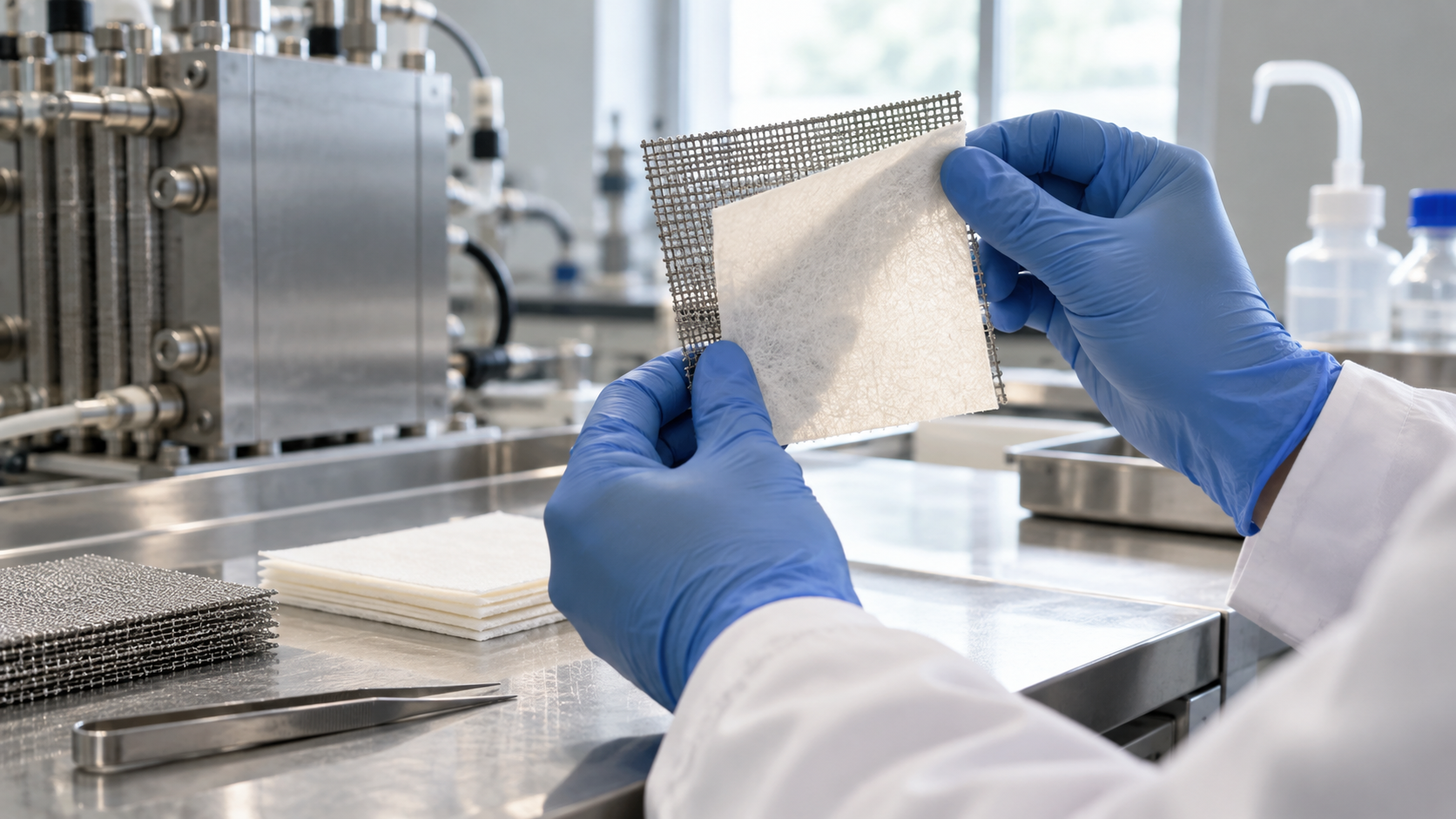
The electrolyte: why KOH
Brauns and Turek report a conductivity of about 95 S/m for KOH at 50 °C against about 65 S/m for the cheaper NaOH, so that KOH is 40 to 50% more conductiveSourced (95 ÷ 65 = about 1.46, consistentOur calculation). Gas solubility, on the other hand, falls as electrolyte concentration rises (salting out), and the effect is slightly stronger in NaOH, so the product gases dissolve more readily in KOHSourced. Choosing for conductivity costs something in gas solubility, which bears on purity — a small trade-off here too (our commentary).
The diaphragm: from asbestos to composites
- History: IRENA writes that asbestos was used until its health hazards became known late in the 20th century, then replaced by ZrO₂-based composite separators such as ZIRFON®Sourced
- Construction: IRENA describes the diaphragm as ZrO₂ stabilised with a PPS mesh. Brauns and Turek give Zirfon™ Perl UTP 500 (Agfa) as an example of a porous separatorSourced
- What is required: the Asahi Kasei paper says a diaphragm needs a high gas barrier, low electrical resistance and excellent thermal and chemical durability, and that porous membranes of aromatic hydrocarbons, or composites of them with inorganic oxides, are commonly usedSourced. The company has also developed a diaphragm surface-modified with hydrophilic inorganic particles and a fluororesin coating
- The thickness tug of war: IRENA explains that thicker diaphragms and spacers used to prevent gas mixing raise resistance and lower efficiencySourced
- A manufacturer’s claim: Agfa says ZIRFON UTP 500+ gives a 2.5% higher hydrogen yield than its UTP 500, with the note that this was measured at 10 kA/m² (1 A/cm²)Sourced (manufacturer’s stated value). In March 2022 Agfa announced that thyssenkrupp nucera had signed a purchase contract for a large volume of ZIRFON membranesSourced (Agfa announcement)
A PEM membrane is a dense polymer that conducts ions, and gas crosses mainly by diffusing through it. An alkaline diaphragm is a porous sheet filled with electrolyte, and ions travel through the liquid in the pores. Gas mixes not only through the diaphragm but also as gas dissolved in the circulating liquid and carried along with it (the Asahi Kasei paper lists these as the two routes of mixingSourced; framing the difference as pores and liquid is our commentary). So the evaluation of a diaphragm depends not only on gas permeability but on wettability (hydrophilicity), pore size and dimensional stability in the electrolyte (our commentary). Asahi Kasei’s use of hydrophilic inorganic particles can be read as one example.
4. Electrodes — nickel at the core, no precious metals
The great attraction of alkaline electrolysis is that its electrodes use no precious metals. Brauns and Turek say nickel is the most-used electrode material, but its overpotentials for oxygen and hydrogen evolution are very high, so catalytic additions are made: iron is a low-cost catalyst for oxygen evolution and molybdenum lowers the overpotential for hydrogen evolutionSourced.
The Asahi Kasei paper says it draws on its chlor-alkali (salt electrolysis) experience, and that for the anode it chose a mixture of transition metal oxides, guided by the Pourbaix diagram (the map of stable potential and pH regions)Sourced. It adds that a reduction treatment by heating in flowing hydrogen raised the conductivity and the specific surface area of the catalyst layer (it hypothesises that the added pore area comes from cracks forming in the layer)Sourced. On the cathode side an elastic metal mattress presses the whole diaphragm evenly.
Brauns and Turek name iron as a low-cost catalyst for the oxygen electrode. IRENA, meanwhile, says nickel alloys should be free of chromium and iron, which can leach out and contaminate the electrodes, lowering efficiency and durabilitySourced. The same element means opposite things depending on whether it is put deliberately where it was designed to be, or dissolves out of a component and ends up where it was not meant to be. Water quality and dissolution from components decide life in alkaline electrolysis just as in PEM (IRENA says iron, chromium, copper, silicon, aluminium and boron in the water can harm the diaphragm and catalystsSourced). (This contrast is our commentary; the two sources do not compare the points directly.)
5. Following variable power — what happens at low current density
Hydrogen purity is normally above 99.9 vol% and oxygen purity 99.0–99.5 vol%Sourced (Brauns and Turek). Because hydrogen and oxygen each form explosive mixtures when the other gas is between 4 and 96 vol%, the technical limit for an emergency shutdown is set at 2 vol%Sourced.
Gas can mix by two routes: permeation through the diaphragm and gas dissolved in the electrolyte and carried by the circulating liquidSourced (Asahi Kasei paper). The second grows in proportion to the electrolyte flow, so a lower flow is preferable; at high current, though, a certain flow is needed to hold down the temperature rise from Joule heating. Asahi Kasei therefore says it introduced automatic control of the electrolyte flow according to the current density, which suppresses overheating at high current and gas contamination at low currentSourced (the manufacturer’s report).
In the measurements cited by Brauns and Turek, with separate electrolyte loops for the anode and cathode sides, the hydrogen concentration in the anode gas stayed below 0.7 vol% in every condition tested (0.05–0.7 A/cm², 1–20 bar). With the loops mixed, it was slightly above 2 vol% even at 0.05 A/cm² and atmospheric pressure, reached 2% at 0.5 A/cm² at 10 bar, and was 2.5% even at 0.7 A/cm² at 20 barSourced (60 °C, KOH about 32 wt%, flow 0.35 L/min). At low current the amount of contaminating gas barely changes while the amount of gas produced falls, so the concentration rises (the review’s own explanation). That is why the part-load floor of most alkaline electrolyzers is held at 10–25% of rated loadSourced.
In IRENA’s 2020 summary the load range is 15–100% for alkaline and 5–120% for PEMSourced. This is, however, a summary as of 2020. Asahi Kasei says it has widened the operating range through flow control according to current density (see above). IRENA writes that some companies claim to have resolved the trade-off between gas permeation and efficiency of the diaphragm with new-generation diaphragmsSourced.
6. A materials engineer’s view (2): every shutdown damages the electrodes — reverse current
When an alkaline electrolyzer is switched off, a “reverse current” flows through the stack in the opposite direction. The Asahi Kasei paper says this corrodes the electrodes, so repeated starts and stops lower electrolysis efficiencySourced. Brauns and Turek say nickel electrodes degrade significantly after 5,000 to 10,000 start/stop cycles, and that operation on photovoltaic power alone reaches 7,000 to 11,000 cycles in 20 to 30 yearsSourced. That is roughly one start and stop a day (7,000 ÷ (20 × 365) = about 0.96 per day; 11,000 ÷ (30 × 365) = about 1.0 per dayOur calculation).
Countermeasures lie in both materials and operation.
- Protective current: IRENA says some systems hold a tiny current to keep the cathode potential from reversingSourced
- Discharge while stopped: Asahi Kasei developed a method that connects an external load to speed up discharge during shutdown, shortening the time the electrodes sit at corrosive potentials, and says it can extend lifetime by about a factor of twoSourced (the manufacturer’s report)
- How long a stop can last: Brauns and Turek say the cathode starts to degrade noticeably below about 0.25 V, so a complete shutdown can be held until that voltage is reached (about 10 minutes has been reported)Sourced
The life of an electrolyzer is set not only by the hours it runs but by how many times it is stopped and how. This is a link between materials and operation that belongs to a method without precious metals (our commentary).
7. Scale-up so far — separating demonstration, commercial and plan
In alkaline cells a single electrode can be made large. IRENA says electrode areas reach up to 3 m²Sourced. The Asahi Kasei paper describes a system at FH2R in Fukushima that stacks 170 cells of 2.7 m² electrode area in seriesSourced. The table below separates, from published material, demonstration, commercial specifications and orders and plans.
| Level | What is published | Source |
|---|---|---|
| Demonstration | FH2R (Namie, Fukushima; NEDO project): began operation in March 2020 with an electrolysis system supplied by Asahi Kasei. Maximum power 12 MW (AC input), hydrogen 300–2000 Nm³/h (variable), maximum ramp rate 500 kW/s, cell internal pressure about 70 kPaG, hydrogen outlet pressure above 0.8 MPaG, hydrogen purity above 99.97 vol% (conforming to ISO 14687:2019 Type I Grade D). More than 13,000 hours of operation at the time of the paper | Fujita et al. (2025) [Source 3] (manufacturer’s report) |
| Demonstration | Kawasaki pilot test plant: four modules, operating since May 2024 with support from NEDO’s Green Innovation Fund | Fujita et al. (2025) [Source 3] |
| Commercial specification | thyssenkrupp nucera “scalum®” 20 MW unit: a single-element cell design based on chlor-alkali experience. The company states that the foundational design was certified by TÜV Rheinland to meet Chapter 4 of ISO 22734:2019 (that standard has since been withdrawn and replaced) | thyssenkrupp nucera technology page [Source 6] (manufacturer’s statement) |
| Commercial scale | The company states “>10 GW of capacity installed”, “2.7 GW delivered across 2024 and 2025”, “>3 GW contracted” and a supply chain of 1.5 GW per year (page undated; viewed 6 October 2026). It lists as reference projects Stegra (Boden, Sweden), Holland Hydrogen 1 (Shell, Rotterdam), Onuba (Moeve, Huelva) and NEOM (Saudi Arabia) | thyssenkrupp nucera technology page [Source 6] (manufacturer’s statement) |
| Plan | Onuba (Moeve, Spain): a supply contract for fifteen 20 MW units, 300 MW in total (18 March 2026). Moeve announced its final investment decision (FID) in early March 2026. The stated production capacity is about 45,000 tonnes of hydrogen a year | thyssenkrupp nucera (2026) [Source 7]. Production capacity is a plan figureNot yet confirmed |
| Plan | Asahi Kasei plans to commercialise a 100 MW-class system based on its demonstration experience, and to start a green chemical demonstration plant with JGC Holdings by fiscal 2030 | Fujita et al. (2025) [Source 3] Not yet confirmed |
The “commercial scale” figures are the manufacturer’s statement. The page does not let us tell installed, delivered and ordered apart, nor alkaline water electrolysis from chlor-alkali. The operating status of NEOM and others has not been confirmed in this article.
8. Our calculation: back-calculating the current density at FH2R
We use the paper’s figures (170 cells, 2.7 m² electrode area per cell, 300–2000 Nm³/h of hydrogen)Our calculation.
- 1 Nm³ of hydrogen = 1 ÷ 0.022414 = 44.6 mol. Two electrons are needed per molecule, so 44.6 × 2 × 96,485 C ÷ 3,600 = about 2,391 Ah
- Every cell in the series stack carries the same current, and hydrogen output scales with the number of cells. At the maximum, 2000 Nm³/h ÷ 170 cells = 11.76 Nm³/h per cell → 11.76 × 2,391 = about 28,100 A
- Electrode area 2.7 m² = 27,000 cm². 28,100 ÷ 27,000 = about 1.04 A/cm² (maximum). At the minimum of 300 Nm³/h it is about 0.16 A/cm² (15% of the maximum)
Assumptions and limits: 100% current efficiency (no hydrogen lost), Nm³ at 0 °C and 1 atm (standard conditions), and that the “2.7 m² electrode area” is the area through which current flows are assumptions set by this article. The real current density would be somewhat higher. The paper does not state a current density, so this value is not a published one.
The result sits somewhat above IRENA’s nominal range (0.2–0.8 A/cm²) at the top, and the minimum is 15% of the maximum — the same level as the part-load floor given by Brauns and Turek (10–25%) and IRENA’s 15%Our calculation. Against PEM (IRENA 1–2 A/cm², DOE target of 3.0 A/cm²), the gap is several-fold. The thick diaphragm and the resistance of a liquid electrolyte can be read as the main reason (our commentary). DOE’s alkaline targets are 1.0 A/cm² for 2026 and 2.0 A/cm² as the ultimate targetSourced.
9. Reading the numbers, evaluation and standards
| Item | DOE alkaline (2022 status → 2026 target → ultimate target) | IRENA summary (December 2020) | Asahi Kasei FH2R (paper) |
|---|---|---|---|
| What the number is | A status and targets for the stack. Performance, durability and capital cost must be met together; electricity at or below 0.03 $/kWh and availability above 90% assumed | A summary of the state of the art in 2020 | The specification of a 10 MW-class demonstration plant (manufacturer’s report) |
| Current density and voltage | 0.5 A/cm² at 1.9 V → 1.0 A/cm² at 1.8 V → 2.0 A/cm² at 1.7 V | Nominal current density 0.2–0.8 A/cm², voltage range 1.4–3 V | Not stated (our back-calculation gives about 0.16–1.04 A/cm²) |
| Electricity use | Stack 51 → 48 → 45 kWh/kg; system 55 → 52 → 48 kWh/kg | Stack 47–66, system 50–78 kWh/kg | Not stated (maximum power of 12 MW AC is given) |
| Degradation and life | Average degradation 3.2 → 2.3 → 2.1 mV/kh; lifetime 60,000 → 80,000 → 80,000 h (end of life = 10% voltage increase) | Stack lifetime 60,000 h (2020); text also says lifetimes above 30 years are proven | More than 13,000 h of operation (at the time of the paper) |
| Operating conditions | Not stated (a targets table) | 70–90 °C, pressure below 30 bar, load range 15–100%, hydrogen purity 99.9–99.9998%, electrode area 10,000–30,000 cm² | Cell internal pressure about 70 kPaG, hydrogen outlet above 0.8 MPaG, purity above 99.97 vol% |
| Capital cost | Stack 250 → 100 → 50 $/kW; system (uninstalled) 500 → 250 → 150 $/kW | Stack 270 $/kW (from 1 MW), system 500–1,000 $/kW (from 10 MW) | Not stated |
All Sourced (DOE [Source 4], IRENA [Source 1], Fujita et al. [Source 3]). Numbers at different levels are set side by side; this is not a ranking. IRENA’s stack lifetime of 60,000 h is from its table, and “over 30 years” from its text.
- The international safety standard: ISO 22734:2019 has been withdrawn and replaced by ISO 22734-1:2025 (Part 1: Safety), published in July 2025Sourced (ISO, checked 5 October 2026). The scope of the old edition included ion-transport media of aqueous bases. The text is paid, so we limit ourselves to the title and scope
- Testing for grid services: ISO/WD TS 22734-2 (testing guidance for grid services) is under development, focusing on alkaline and PEM electrolysersNot yet confirmed
- Test methods for performance and durability: the JRC report (EUR 30752 EN, 2021) sets out harmonised operating conditions and testing protocols for low-temperature water electrolysis including alkaline (AWE)Sourced
10. Challenges and limits
(1) Long-term data under variable power are limited
Within the scope of this article we could not confirm a case in which a manufacturer has published, as primary information, a long-term degradation rate for operation following renewable energy. The figures from Brauns and Turek and the Asahi Kasei paper come from tests with stated conditions and from a manufacturer’s report.
(2) Constraints on pressure and purity
In IRENA’s summary the operating pressure of alkaline electrolysis is below 30 bar. Higher pressure means more dissolved gas and a worse mixing problem (Brauns and Turek), so large differential-pressure operation like PEM’s is hardSourced.
(3) Manufacturers’ scale figures cannot be broken down
thyssenkrupp nucera’s “over 10 GW installed” and similar figures cannot be split, from the page, into alkaline water electrolysis and chlor-alkali, or into installed, delivered and ordered. The operating status of NEOM and others is not confirmed.
(4) What is not covered
Comparison with other technologies (cost, installed base), resource questions such as nickel, the state of deployment in China, AEM and cell structures other than zero-gap, diaphragm manufacturers’ technical data sheets (Agfa’s must be requested and could not be checked), and the handling of hydrogen and electrolyte are not covered.
- Alkaline electrolysis uses KOH solution, nickel-based electrodes and a ZrO₂-based porous diaphragm, and no precious metalsSourced
- The weak point is gas mixing at low current. With mixed electrolyte loops, 2 vol% is reached even at 0.5 A/cm² at 10 bar (60 °C, laboratory conditions)Sourced
- Every shutdown lets reverse current damage the electrodes. Nickel electrodes degrade significantly after 5,000–10,000 start/stops, which on photovoltaic power alone is about one a daySourcedOur calculation
- FH2R (10 MW class, demonstration) back-calculates to at most about 1.04 A/cm² with 170 cellsOur calculation, several times lower than PEM
- Read commercial scale in two parts: the manufacturer’s statements (over 10 GW installed and so on) and plans (Onuba, 300 MW)Not yet confirmed
11. Glossary
- KOH
- Potassium hydroxide: a strongly alkaline electrolyte whose aqueous solution conducts well.
- Diaphragm
- A porous sheet that separates the gases and passes ions. Distinct from an ion-exchange membrane.
- Zirfon
- Agfa’s trade name for its diaphragm: a porous ZrO₂-containing layer on a PPS mesh.
- Zero gap
- A layout with electrodes pressed directly against the diaphragm, removing the gap between electrodes.
- Reverse current
- Current that flows backward through the stack when power is cut. It damages the electrodes.
- Part load
- Operation at less than rated output.
- Turndown ratio
- The ratio of maximum to minimum output at which a plant can run.
- vol%
- Percent by volume. Here, the share of hydrogen mixed into the oxygen.
- Nm³
- Normal cubic metre: gas volume converted to standard conditions (0 °C, 1 atm).
- FH2R
- Fukushima Hydrogen Energy Research Field (Namie): a NEDO demonstration.
- Salting out
- The drop in gas solubility as salt concentration rises.
- mV/kh
- Rise in cell voltage per 1000 hours: the unit of degradation rate.
12. Primary sources
- IRENA “Green hydrogen cost reduction: Scaling up electrolysers to meet the 1.5°C climate goal”, December 2020 (PDF) — irena.org
- Brauns J, Turek T “Alkaline Water Electrolysis Powered by Renewable Energy: A Review”, Processes 8(2), 248 (2020, peer-reviewed) — doi.org/10.3390/pr8020248
- Fujita Y et al. (Asahi Kasei) “Development and Demonstration of Large-scale Alkaline Water Electrolysis System ‘Aqualyzer’”, Electrochemistry 93(11), 117007 (2025, peer-reviewed) — doi.org/10.5796/electrochemistry.25-00129
- U.S. Department of Energy (DOE) “Technical Targets for Liquid Alkaline Electrolysis” (viewed 5 October 2026) — energy.gov
- U.S. Department of Energy (DOE) “Technical Targets for Proton Exchange Membrane Electrolysis” (viewed 5 October 2026) — energy.gov
- thyssenkrupp nucera “Alkaline Water Electrolysis” technology page (viewed 6 October 2026) — thyssenkrupp-nucera.com
- thyssenkrupp nucera “thyssenkrupp nucera Supplies Electrolyzers for Moeve to Build Southern Europe’s Largest Green Hydrogen Project”, 18 March 2026 — thyssenkrupp-nucera.com
- Agfa “Agfa sets a new efficiency standard in the production of green hydrogen with its ZIRFON UTP 500+ electrolysis membrane” — agfa.com
- Agfa “Agfa’s ZIRFON separator membrane selected by thyssenkrupp nucera for large-scale green hydrogen projects”, 9 March 2022 — agfa.com
- ISO “ISO 22734-1:2025 Hydrogen generators using water electrolysis — Part 1: Safety” — iso.org
- ISO “ISO 22734:2019 Hydrogen generators using water electrolysis — Industrial, commercial, and residential applications” (withdrawn) — iso.org
- European Commission JRC Tsotridis G, Pilenga A, “EU harmonised protocols for testing of low temperature water electrolysers”, EUR 30752 EN (2021) — publications.jrc.ec.europa.eu
13. Claim-to-source audit
| Claim in the text | Basis | Label |
|---|---|---|
| That alkaline electrolysis was the only technology used from the 19th century to the first half of the 20th, with asbestos as the diaphragm, later replaced by ZrO₂-based composite separators such as ZIRFON®. The table values (operating temperature 70–90 °C, pressure 1–30 bar, KOH 5–7 mol/L, separator “ZrO₂ stabilized with PPS mesh”, nickel-coated perforated stainless-steel electrodes and bipolar plates, frames and seals of PSU, PTFE and EPDM). That thick diaphragms and spacers raise resistance and lower efficiency. Electrode areas up to 3 m². That nickel alloys should be free of chromium and iron and that Fe, Cr, Cu, Si, Al and B in water can do harm. The example of a tiny protective current preventing cathode potential reversal. The 2020 summary values (nominal current density 0.2–0.8 A/cm², voltage 1.4–3 V, load range 15–100% (PEM 5–120%), hydrogen purity 99.9–99.9998%, stack 47–66 and system 50–78 kWh/kg, lifetime 60,000 h, electrode area 10,000–30,000 cm², stack 270 $/kW, system 500–1,000 $/kW). The text on robust designs and lifetimes above 30 years. That some companies claim to have resolved the diaphragm trade-off | IRENA (December 2020)[Source 1] https://www.irena.org/-/media/Files/IRENA/Agency/Publication/2020/Dec/IRENA_Green_hydrogen_cost_2020.pdf | Sourced |
| That the electrolyte is 20–30 wt% KOH, with conductivity best at 50–80 °C. That KOH conductivity is about 95 S/m at 50 °C and NaOH about 65 S/m, KOH being 40–50% higher. That gas solubility falls with concentration (salting out) and is higher in KOH. The zero-gap layout. That Zirfon™ Perl UTP 500 (Agfa) is an example of a porous separator. That nickel is the most-used electrode, with iron catalysing oxygen evolution and molybdenum hydrogen evolution. Hydrogen purity of 99.9 vol% or more, oxygen 99.0–99.5 vol%, and 2 vol% as the emergency-shutdown limit. The measurements (60 °C, KOH about 32 wt%, 0.35 L/min, 0.05–0.7 A/cm², 1–20 bar): below 0.7 vol% with separate loops; with mixed loops slightly above 2% at atmospheric pressure and 0.05 A/cm², 2% at 0.5 A/cm² at 10 bar and 2.5% at 0.7 A/cm² at 20 bar. A part-load floor of 10–25% of rated load. Nickel electrodes degrading significantly after 5,000–10,000 start/stop cycles, and 7,000–11,000 cycles in 20–30 years on photovoltaic power alone. The cathode degrading below about 0.25 V, with about 10 minutes reported | Brauns and Turek (2020, peer-reviewed)[Source 2] https://doi.org/10.3390/pr8020248 | Sourced |
| The properties required of a diaphragm (high gas barrier, low electrical resistance, thermal and chemical durability), the common use of aromatic-hydrocarbon porous membranes and composites with inorganic oxides, and the development of a diaphragm surface-modified with hydrophilic inorganic particles and a fluororesin coating. Nickel bipolar cell frames, the elastic metal mattress, an anode catalyst of mixed transition metal oxides with a hydrogen-reduction heat treatment. That reverse current corrodes electrodes and repeated start/stops lower efficiency, and that discharge through an external load roughly doubles lifetime. The two routes of mixing (permeation, dissolution) and automatic electrolyte flow control by current density. FH2R (operation from March 2020, maximum 12 MW AC, 300–2000 Nm³/h, 500 kW/s, about 70 kPaG, above 0.8 MPaG, above 99.97 vol%, 170 cells of 2.7 m², more than 13,000 hours), the Kawasaki pilot plant (four modules, May 2024), and the plan for a 100 MW-class system and a demonstration plant with JGC by fiscal 2030 | Fujita et al. (2025, Electrochemistry)[Source 3] https://doi.org/10.5796/electrochemistry.25-00129 | Sourced |
| Every item in the DOE alkaline table (0.5 A/cm² at 1.9 V, 1.0 at 1.8 V, 2.0 at 1.7 V; stack 51/48/45 kWh/kg (65/69/74% LHV); system 55/52/48 kWh/kg; degradation 3.2/2.3/2.1 mV/kh; lifetime 60,000/80,000/80,000 h; stack 250/100/50 $/kW; system 500/250/150 $/kW) and the conditions that targets be met together, electricity at or below 0.03 $/kWh, availability above 90% and end of life at a 10% voltage increase | U.S. DOE (viewed 5 October 2026)[Source 4] https://www.energy.gov/eere/fuelcells/technical-targets-liquid-alkaline-electrolysis | Sourced |
| The DOE PEM current densities set beside them for reference (2.0 A/cm² at 1.9 V, 3.0 at 1.8 V, 3.0 at 1.6 V) | U.S. DOE (viewed 5 October 2026)[Source 5] https://www.energy.gov/eere/fuelcells/technical-targets-proton-exchange-membrane-electrolysis | Sourced |
| thyssenkrupp nucera’s statements: the scalum® 20 MW unit, the single-element design from chlor-alkali, over 10 GW installed, 2.7 GW delivered across 2024 and 2025, over 3 GW contracted, a supply chain of 1.5 GW a year, the reference projects (Stegra, Holland Hydrogen 1, Onuba, NEOM), and certification of the foundational design by TÜV Rheinland to Chapter 4 of ISO 22734:2019 | thyssenkrupp nucera technology page (manufacturer’s statement, viewed 6 October 2026; page undated)[Source 6] https://www.thyssenkrupp-nucera.com/technologies/alkaline-water-electrolysis | Sourced |
| Onuba (Moeve, Huelva): a supply contract for fifteen 20 MW units totalling 300 MW (18 March 2026), Moeve’s final investment decision in early March 2026, and the stated capacity of about 45,000 tonnes of hydrogen a year | thyssenkrupp nucera press release. The production capacity is a plan figure, not a result[Source 7] https://www.thyssenkrupp-nucera.com/newsroom/news-press-releases/thyssenkrupp-nucera-supplies-electrolyzers-for-moeve-to-build-southern-europes-largest-green-hydrogen-project | Not yet confirmed |
| That ZIRFON UTP 500+ gives a 2.5% higher hydrogen yield than the UTP 500, measured at 10 kA/m² | Agfa announcement (manufacturer’s stated value)[Source 8] https://www.agfa.com/corporate/news-item/agfa-sets-a-new-efficiency-standard-in-the-production-of-green-hydrogen-with-its-zirfon-utp-500-electrolysis-membrane/ | Sourced |
| That Agfa announced on 9 March 2022 that thyssenkrupp nucera had signed a purchase contract for a large volume of ZIRFON membranes | Agfa announcement (9 March 2022)[Source 9] https://www.agfa.com/specialty-products/news/agfas-zirfon-separator-membrane-selected-by-thyssenkrupp-nucera-for-large-scale-green-hydrogen-projects/ | Sourced |
| That ISO 22734:2019 was withdrawn and replaced by ISO 22734-1:2025 (Part 1: Safety, July 2025); the scope of the old edition; and that ISO/WD TS 22734-2 is under development | ISO pages (checked 5 October 2026). Whether Part 2 will be published is not yet confirmed[Source 10] https://www.iso.org/standard/82766.html [Source 11] https://www.iso.org/standard/69212.html | Sourced |
| That the JRC published a report (EUR 30752 EN, 2021) on harmonised operating conditions and testing protocols for low-temperature water electrolysis including alkaline | JRC Publications Repository[Source 12] https://publications.jrc.ec.europa.eu/repository/handle/JRC122565 | Sourced |
| 95 ÷ 65 = about 1.46 (KOH about 46% more conductive than NaOH). 7,000 ÷ (20 × 365) = about 0.96 per day and 11,000 ÷ (30 × 365) = about 1.0 per day. The FH2R back-calculation: 1 Nm³ = 44.6 mol, 2,391 Ah per Nm³, 2000 ÷ 170 = 11.76 Nm³/h per cell, about 28,100 A, 27,000 cm², about 1.04 A/cm² (maximum) and about 0.16 A/cm² at 300 Nm³/h (15% of maximum) | Our calculation. 100% current efficiency, Nm³ at 0 °C and 1 atm, and 2.7 m² as the area through which current flows are assumptions set by this article; the paper does not state a current density | Our calculation |
| Long-term degradation rates under renewable-power operation, diaphragm manufacturers’ technical data sheets (Agfa’s must be requested), the breakdown of thyssenkrupp nucera’s figures (alkaline electrolysis versus chlor-alkali; installed, delivered, ordered) and the operating status of NEOM and others | Could not be confirmed from primary sources within the scope of this article, so none is stated | Commentary |
| The reactions and the movement of OH⁻. The trade-off between KOH conductivity and gas solubility, the difference in how the diaphragm works compared with the PEM membrane, the contrast between iron as a catalyst and as a contaminant, the reading of why current density is low, and the framing that the number and manner of stops set lifetime | Our summary and commentary based on published content. Not views expressed by any of the institutions | Commentary |
| That Fig. 2, Fig. 5, Fig. 6 and Fig. 4 are explanatory drawings rather than real design or measurement diagrams, and that Fig. 1 and Fig. 3 are AI-generated images | Our note | Commentary |
Last updated 6 October 2026. Sources are limited to primary material (official documents of international bodies, governments, standards bodies and manufacturers, and peer-reviewed papers). Because the article includes structural readings and materials-design interpretations, those are marked as Commentary and kept separate from sourced fact. Long-term degradation under renewable-power operation, diaphragm manufacturers’ data sheets, the breakdown of thyssenkrupp nucera’s figures and the operating status of NEOM and others could not be confirmed and are not stated. The table in Chapter 9 and Fig. 6 set side by side numbers of different origin and level and are not a ranking. Fig. 2, Fig. 5, Fig. 6 and Fig. 4 are vector drawings and Fig. 1 and Fig. 3 are AI-generated images; none of them shows a real cross-section, equipment or product.