TECHNOLOGY EXPLAINER
Hydrogen Co-Firing in Gas Turbines
— when they say "30%", 30% of what?
Hydrogen co-firing means burning hydrogen mixed into natural gas in a gas turbine to cut fuel-derived CO2. But "30% co-firing" is usually 30% by volume, not 30% of the energy: 30% hydrogen by volume is only about a tenth of the fuel's heat. In the combustor the problems are flashback, nitrogen oxides (NOx) and combustion oscillation; in the hot section the issue is not hydrogen itself but the extra water vapour from burning it. This article sets out manufacturers' stated values with their conditions, the demonstrations on record, and what a materials engineer should take from them, using published primary sources.
- What hydrogen co-firing in gas turbines is (the short version)
- Our calculation: "30% co-firing" is 30% of what?
- Three combustor problems — flashback, NOx, combustion oscillation
- Combustor types and manufacturers' stated values — reading the conditions
- A materials engineer's view (1): where hydrogen touches and where water vapour touches are different places
- Hot-section materials and water vapour — what a U.S. NETL study found
- A materials engineer's view (2): combustion oscillation is tied to wall cooling
- Demonstrations and plans — what official materials confirm
- System-level constraints
- Challenges, and what we could not confirm
- Glossary / Primary sources / Claim-to-source audit
Sourced = stated in published material (link given)
Our calculation = a figure this article derived, with the assumptions spelled out
Not yet confirmed = a plan or target with no confirmed outcome
Materials-design interpretations are marked as Commentary, and weakly supported ideas as Inference. Performance figures are the manufacturer's stated values and are read together with their conditions (model, combustor type, treatment of NOx).
This article explains the principles, materials and demonstrations of hydrogen co-firing in gas turbines. Hydrogen is a flammable gas, and power-plant use is governed by laws and standards. It is not advice on any particular model or operating method; actual design, modification and operation must follow the manufacturer, national law and expert review.
1. What hydrogen co-firing in gas turbines is (the short version)
- What is done: hydrogen is mixed into the fuel of a gas turbine that normally burns natural gas. Burning hydrogen alone is "hydrogen firing". Hydrogen gives no CO2 when burned, so every share replaced cuts fuel-derived CO2 accordingly.
- How far it has got (the companies' own announcements): MHI (Mitsubishi Power) says it ran a 1,650°C-class M501JAC on 30% hydrogen by volume, grid-connected, from part load to full load (November 2023), and completed a 50% by volume test on an M501GAC (June 2025). Siemens Energy says it ran an SGT-400 (about 13 MW) on 100% hydrogen in its low-emissions (DLE) mode (October 2023). GE Vernova says its latest HA-class machines with the DLN2.6e combustor can burn up to 50% hydrogenSourced.
- The hard parts: flashback, NOx and combustion oscillation in the combustor; more water vapour in the hot section; and the choice of materials for the hydrogen fuel system. Later chapters go through the primary sources for each.
Materials for handling hydrogen itself (pipes, tanks) are covered in the "Hydrogen Pipelines and Hydrogen Embrittlement" and "High-Pressure Hydrogen Tanks" articles, and the combustion of hydrogen in piston engines in the "Hydrogen Combustion Engines" article. This article stays with the gas-turbine combustor and hot section.
2. Our calculation: "30% co-firing" is 30% of what?
A co-firing rate can be stated as a share by volume (or by mole) or as a share by heat. MHI states that its hydrogen mixing ratios are by volume, and most of the manufacturers' announcements in this article are by volume. Because hydrogen has a low heat content per unit volume, 30% hydrogen by volume is only about a tenth of the heat. MHI's handbook gives the conversionSourced.
| Hydrogen (vol%) | Heat share (methane plus hydrogen; our calculation) | MHI handbook | Fuel volume flow for the same heat (methane alone = 1) |
|---|---|---|---|
| 10% | about 3.2% | — | about 1.08 times |
| 20% | about 7.0% | 6.1 cal% | about 1.16 times |
| 30% | about 11.4% | 10.1 cal% | about 1.27 times |
| 50% | about 23.2% | — | about 1.54 times |
| 79.3% | about 53.6% | 50 cal% | about 2.24 times |
| 100% | 100% | — | about 3.32 times |
The "MHI handbook" column is Sourced (MHI Hydrogen Power Generation Handbook [Reference 3]). The other columns are Our calculation; the assumptions are in the box below.
Assumptions: ideal gas, so volume share = mole share. Lower heating values come from NIST enthalpies of formation (gas)Sourced: hydrogen = enthalpy of formation of water (gas), 241.826 kJ/mol; methane = 393.51 + 2 × 241.826 − 74.87 = 802.29 kJ/mol (CO2 −393.51, water −241.826, methane −74.87 kJ/mol)Our calculation.
Heat share: at 30%, 0.3 × 241.8 ÷ (0.3 × 241.8 + 0.7 × 802.3) = 72.5 ÷ 634.2 = about 11.4%. Volume-flow ratio: the flow needed for the same heat is 802.3 ÷ 634.2 = about 1.27 times (30%), and for 100% hydrogen 802.3 ÷ 241.8 = about 3.32 times.
Relation to MHI's numbers: back-calculating the heating value per mole of the natural gas from MHI's three points (20% → 6.1, 30% → 10.1, 79.3% → 50 cal%) gives about 922 to 931 kJ/mol at all three points, i.e. about 1.15 to 1.16 times methane. MHI's natural gas can therefore be read as containing hydrocarbons heavier than methane and having a higher heating value (Inference; the composition is not given in the material).
Limits: the "heat share" here is hydrogen's share of the fuel's heat, not the CO2 reduction itself. If efficiency is unchanged, it comes close to the reduction in fuel-derived CO2. For example, Georgia Power and Mitsubishi Power report that a 50% by volume blend cuts CO2 by about 22% against 100% natural gas [Reference 5]Sourced, consistent with the calculation above (about 23% at 50%). MHI's handbook puts the CO2 reduction for 30% co-firing at about 12% in the text but at about 10% in the figure's numbers (340 → 305 g/kWh); the material does not say why the bases differ.
What a larger volume flow means
For the same heat, the more hydrogen there is, the larger the fuel volume flow (right-hand column above). That bears on the dimensions of fuel piping, valves and fuel nozzles and on fuel velocity (commentary by this article). GE Vernova explains that, depending on the model, conversion for hydrogen blending may require a blending skid, controls, fire protection, hazardous-area equipment, nitrogen purge, a new fuel system (including piping and tubing) and engine modificationsSourced.
3. Three combustor problems — flashback, NOx, combustion oscillation
The standard for low-NOx operation in today's gas turbines is lean premixed (LPM) combustion, in which fuel and air are mixed first and then burned lean. Adding hydrogen brings the properties of its flame (fast propagation, fast diffusion, high flame temperature) to bear as three problems. MHI names flashback, combustion pressure fluctuation and NOx as the obstacles to 30% co-firingSourced. A peer-reviewed review by researchers at UCL and elsewhere (2021) sets them out as followsSourced.
| Problem | What the primary sources confirm |
|---|---|
| 1 Flashback and autoignition | Flashback is the upstream propagation of the flame front from the combustion zone into the premixing section when the local turbulent flame speed exceeds the flow velocity of the reactants; it can lead to local flame holding, overheating and hardware damage. Hydrogen's higher turbulent flame speed than natural gas raises the propensity. The well-researched mechanisms are propagation due to combustion instabilities, in the core flow, within boundary layers, and combustion-induced vortex breakdown. Inlet pressures and temperatures in modern gas turbines are high enough for autoignition; hydrogen's autoignition temperature is only marginally higher than methane's, but its ignition delay time is much shorter, and autoignition can occur if the delay is shorter than the mixing residence time |
| 2 NOx | At typical LPM stoichiometry the adiabatic flame temperature of pure hydrogen is over 150 K higher than methane's. In a fixed gas turbine configuration NOx will rise unless operating conditions are adapted, for example by shifting to a leaner equivalence ratio. GE Vernova also writes that "more NOx may be produced compared to natural gas" |
| 3 Combustion oscillation (thermoacoustic instability) | Pressure oscillation amplitudes can reach a large percentage of the mean pressure. Left uncontrolled they cause component vibration, higher heat transfer, flame blow-off and flashback, and in the worst case structural damage. LPM combustors use almost no film cooling or dilution air, so acoustic damping is low. Through its effect on flame structure and position, hydrogen can have either a stabilising or a destabilising effect. MHI says the interval in which hydrogen burns is particularly short, so flame and oscillation are more likely to match, and that once oscillation occurs it "will destroy the combustor in an instant" |
All Sourced (UCL review, Beita et al. 2021 [Reference 1], MHI handbook [Reference 3], GE Vernova [Reference 13]). The phrase "destroy the combustor in an instant" is a remark by an MHI engineer reported in the company's material.
MHI's handbook gives the flame colour of hydrogen as pale and translucent (hard to see), methane as blue and ammonia as orangeSourced. GE Vernova explains that because hydrogen is more flammable than natural gas, the turbine enclosure ventilation must be designed to keep hydrogen outside its explosive limits, and gas and flame detection systems set up for hydrocarbon fuels may need to be supplemented to detect hydrogenSourced. These are descriptions of design considerations, not advice for any specific installation.
4. Combustor types and manufacturers' stated values — reading the conditions
What "up to X%" means depends on the combustor type and on how NOx is handled. MHI's handbook sets out the development status of hydrogen gas-turbine combustors in three typesSourced.
| Type (MHI's naming) | Low-NOx measure | Combustion temperature class | Hydrogen content and development status (MHI handbook) |
|---|---|---|---|
| Type 1: diffusion combustion | Nitrogen dilution, water or steam addition | 1,200 to 1,400°C class | 100%: development completed |
| Type 2: premixed combustion | Dry low NOx (DLN) | 1,650°C class | 30%: development completed. 50%: combustion test successful in 2022 |
| Type 3: multi-cluster | Dry low NOx (DLN) | 1,650°C class | 100%: development scheduled to be completed after 2025Not yet confirmed |
All Sourced (MHI Hydrogen Power Generation Handbook [Reference 3]). The status of Type 3 is as of the handbook; we could not confirm what has been achieved since.
An MHI engineer explains the idea behind Type 3. Mixing hydrogen and air quickly in a small space raises the risk of flashback, while mixing them in a large space with swirl lets the flame return. So the usual design with eight nozzles is replaced by many small nozzles that inject air and spray hydrogen into it, mixing on a small scale without swirl (distributed lean burning). Here too the shape and material of the nozzle are said to be the keySourced.
Manufacturers' "X%" figures, set side by side with their conditions
The figure below arranges the "up to X%" figures that companies have published by product specification / stated value, demonstration and under development / plan. Because the conditions differ, it is not a ranking. Even for the same SGT-400 the number comes in three versions depending on conditions: 30 vol% with DLE (low-NOx) burners, 65 vol% with diffusion burners (NOx not abated), and 100% in the demonstration.
5. A materials engineer's view (1): where hydrogen touches and where water vapour touches are different places
Asked "what does burning hydrogen do to materials?", the first thing to settle is which place you mean. Inside a gas turbine, some places touch hydrogen and others touch gas containing the water vapour left after hydrogen burns, and the materials problems are different.
| Place | What it touches | Materials issues (as far as primary sources confirm) |
|---|---|---|
| Fuel supply system (piping, valves, joints, seals) | Hydrogen itself, at relatively low temperature | NASA's hydrogen safety standard divides hydrogen embrittlement into environmental, internal and reaction forms and says stronger alloys are more susceptible [Reference 14]. GE Vernova says conversion may need a "new fuel system, including piping and tubing" and a "nitrogen purge system" [Reference 13]. We could not confirm data on specific materials used in gas-turbine fuel systems |
| Combustor (nozzles, liner, thermal barrier coating) | Flame and hot combustion gas | Overheating from flashback and autoignition, and vibration loads from combustion oscillation (Chapter 3). MHI says it optimises by trial and error the shape and material of the fuel nozzle and combustor and the quality and particle size of the ceramic thermal-insulation coating [Reference 3] |
| Hot section (turbine blades and vanes, thermal barrier coating) | Post-combustion gas; burning hydrogen increases water vapour | What more water vapour does to protective oxides and thermal barrier coatings — a U.S. NETL study exists (next chapter). We could not confirm life data from real hydrogen-fired machines |
The second and third columns are Sourced (NASA [Reference 14], GE Vernova [Reference 13], MHI [Reference 3]). Dividing by place is commentary by this article. We did not check the effect of unburned hydrogen remaining in the post-combustion gas.
NASA's standard says that for many metals internal and environmental embrittlement is greatest around 200 to 300 K, while reaction embrittlement occurs more readily at high temperatureSourced. The upstream fuel system is where relatively cool, high-pressure hydrogen meets metal, and hydrogen-embrittlement knowledge applies directly (commentary by this article). The hot section, by contrast, sees gas after the hydrogen has been consumed, and water vapour becomes the main actor. "Hydrogen embrittles metal" alone does not settle the materials story for gas turbines.
6. Hot-section materials and water vapour — what a U.S. NETL study found
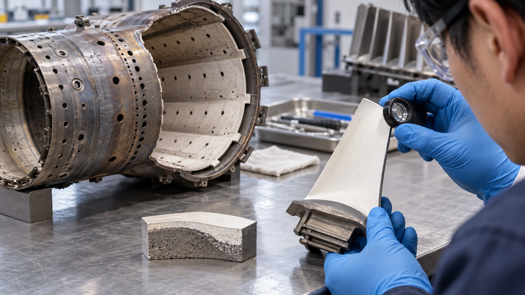
One of the most concrete primary sources on hot-section materials and hydrogen is a research report from the University of California, Irvine (Professor Daniel Mumm), funded by the U.S. DOE's NETL (research September 2010 to August 2013, issued 28 June 2014). It covers the effects of coal-derived syngas and high-hydrogen-content (HHC) fuels on protective oxides and thermal barrier coatings (TBCs), and it is not a report on hydrogen-fired gas turbines as such. It should be read with that in mind.
| Item | What the report says |
|---|---|
| Amount of water vapour | High-hydrogen fuels raise water vapour in the combustion zone. In an NETL study cited by the report, water vapour is 12 to 14% of turbine exhaust, 25 to 30% if steam is injected to suppress NOx, which can be up to four times the figure for natural gas combustion |
| Field tests of real machines | In field tests of MCrAlY bond coats, syngas produced more "non-ideal" oxide (spinel) in the thermally grown oxide (TGO) than natural gas did. The ideal is a thin (under 5 µm), continuous, protective α-Al2O3 film between the bond coat and the YSZ |
| Laboratory tests | Oxidation in atmospheres with 0 to 45 vol% water vapour. The amount of spinel formed in the early (transient) stage depends on the water-vapour content of the atmosphere. 10 vol% is an average combustion environment and 30 vol% the highest expected for IGCC with steam addition. Spinel thickness ranged from 1 to 33 µm, roughly equivalent to the field-test results |
| Pitfalls in testing | At high temperature in water vapour, oxides volatilise and redeposit, distorting the apparent result. Al-depleted surfaces grew large amounts of non-ideal oxide that evolved metal hydroxides redepositing on other surfaces; transient spinel volatilised away with time and water-vapour content. The report says conclusions in the literature that did not account for volatilisation should be re-evaluated |
| Volatility of the YSZ stabiliser | Volatility of Y2O3 was examined in high-water-vapour atmospheres at 1,000 to 1,500°C. Impurity deposits from the apparatus plagued the tests; with a platinum liner fitted, volatility was negligible at the temperatures tested. Conclusion: no significant evidence that water vapour degrades YSZ through preferential volatilisation of the stabiliser yttria |
| Phase destabilisation of the TBC | Raman and XRD were used to see whether the rate at which YSZ's t′ phase changes to cubic and monoclinic phases differs between dry and high-water-vapour environments (1,300°C, 20 kPa water-vapour pressure). The report says that "additional verification is needed" but the results suggest an important role for fuel type in TBC degradation kinetics |
| Molten deposits (CMAS type) | Impurities and ash in fuel form deposits that are molten at operating temperature, infiltrate the TBC and attack it. In isothermal tests a conventional sprayed coating (APS) was infiltrated through its whole thickness and lost its structure, whereas a segmented (vertically cracked) coating was only partly infiltrated; coating microstructure greatly affected the damage |
All Sourced (NETL / UC Irvine final report, 2014 [Reference 2]). This is a study of syngas and high-hydrogen-content fuels and is about ten years old. It cannot be read as a conclusion for real hydrogen-fired machines.
The merit of this report is that it separated the effects one at a time. For the protective oxide it confirmed that the amount of "non-ideal" oxide (spinel) formed in the transient stage depends on the water-vapour content, yet it found no evidence that the YSZ stabiliser volatilises in water vapour and degrades the coating, and the effect on the rate of TBC phase change is described as needing "additional verification". The major damage to the TBC came less from water vapour itself than from infiltration by molten deposits formed by impurities in fuel and air, and the coating's microstructure governed the outcome.
On the experimental side, the report warns that volatilisation and redeposition artefacts can distort results, so growth and volatilisation have to be looked at together when evaluating oxidation in water vapour. Between the observation that "degradation got faster when the environment changed" and the conclusion that "water vapour is the cause" there is a piece of separating work to be done (commentary by this article).
7. A materials engineer's view (2): combustion oscillation is tied to wall cooling
As Chapter 3 showed, the review says premixed combustors use almost no wall-cooling or dilution air, so acoustic damping is low and combustion oscillation is more likelySourced. A design that trims wall-cooling air for low NOx is therefore also a design that trims the margin against oscillation.
- MHI's account: mixing hydrogen and air in a confined space brings the fuel-nozzle jets and the flame closer, making flashback more likely. Once oscillation occurs the combustor is destroyed in an instant. So, besides adjusting where and how fuel burns, MHI keeps adding measures such as a sound-absorbing device and keeps optimising the shape and material of the nozzle and combustor and the quality and particle size of the ceramic thermal-insulation coating [Reference 3]Sourced.
- Reading: low NOx (trimming cooling air), acoustic stability (securing damping), flashback suppression (keeping the flame away from the nozzle) and component heat resistance pull against one another. From the materials side, better heat and thermal-barrier performance opens room to use less cooling air and spend it on the other constraints (commentary by this article; the material gives no specific figures).
8. Demonstrations and plans — what official materials confirm
Demonstrated facts are separated from plans and targets in the table. The figures are the companies' announcements, not independent verification, and most are hydrogen share by volume.
| Project | Confirmed facts (date of announcement) | Plans and unconfirmed items |
|---|---|---|
| HYFLEXPOWER (Saillat-sur-Vienne, France; Siemens Energy, ENGIE and others) | Hydrogen made by a 1 MW electrolyser is stored in a tank of almost one tonne and used in an SGT-400. 15 December 2022: tests with 30 vol% hydrogen and 70 vol% natural gas completed [Reference 9]. Announcement dated 14 October 2023: turbines with dry low emissions technology shown able to run on up to 100% hydrogen [Reference 8]. Funded by EU Horizon 2020 (grant agreement 884229) | Extending operation to industrial heat and other modes, and exploring commercialisationNot yet confirmed |
| T-Point 2 at Takasago Hydrogen Park (MHI, Hyogo, Japan) | 30 November 2023: a 1,650°C-class M501JAC (566 MW rated validation plant) ran on 30 vol% hydrogen with natural gas from part load to full load. Grid-connected, using hydrogen made and stored on the same site, from a project subsidised by NEDO, with a DLN combustor [Reference 4] | MHI announced then that in 2024 it would test 100% hydrogen firing on an H-25 (40 MW class) and a 50% blend after expanding storage. We could not confirm the resultsNot yet confirmed |
| Georgia Power, Plant McDonough-Atkinson (US, MHI) | On an M501GAC (about 283 MW) a 20 vol% test in 2022, then in May to June 2025 several blends from 5 to 50%, completing 50 vol% at part and full load (announced 16 June 2025). Reported CO2 about 22% lower than 100% natural gas [Reference 5] | Georgia Power is developing three hydrogen-capable Mitsubishi Power simple-cycle turbines at Plant Yates (plan)Not yet confirmed |
| Intermountain Power Project "IPP Renewed" (Utah, US, MHI) | Two M501JAC units (840 MW net) delivered in 2023 [Reference 6]. The project site describes "new natural gas-fueled electricity generating units capable of utilizing hydrogen" and shows construction 97% complete (at the time of viewing) [Reference 7] | Plan: 30 vol% hydrogen at start-up in 2025 and 100% hydrogen by 2045 [References 6 and 18]. We could not confirm whether hydrogen co-firing operation has actually begunNot yet confirmed |
| GE Vernova examples (2024 material) | NYPA Brentwood: blending hydrogen with natural gas in an LM6000 demonstrated in 2022. Huizhou, China: 9HA.01 units running a 10 vol% blend since 2023 | Duke Energy's Debary (7E, 100% by volume, from 2025) and EnergyAustralia's Tallawarra B (9F.05 blends, from 2025) were "intended" as of the material. We could not confirm later resultsNot yet confirmed |
The "Confirmed facts" column is Sourced (company announcements [References 4 to 9, 13, 18]). GE Vernova also states in another page that it has "120+" units running on hydrogen and associated fuels with "10M+" operating hours, but these include process gases containing hydrogen and differ in conditions from pure-hydrogen or high-share co-firing (the 2021 figure in the 2024 material was over 100 units and over 8 million hours). MHI likewise says it has supplied gas turbines to about 30 plants using hydrogen as fuel, with over 3.5 million operating hours (the fuel composition is not given).
9. System-level constraints
Even when the combustor can take hydrogen, constraints remain at the level of the power plant. Two points can be confirmed from the manufacturers' own material.
- Round-trip efficiency: Siemens Energy's white paper (2026) says the round-trip efficiency from renewable power through hydrogen back to power in a combined-cycle gas turbine can reach only up to 35 to 40% under favourable conditionsSourced. It adds that the levelised cost of electricity (LCOE) from green hydrogen is currently higher than from blue hydrogen. The company expects that, in regions with abundant low-cost renewables, pairing them with hydrogen-fired plants to cover residual load is the most economical path (the company's view).
- Fuel price: a GE Vernova document (2024) expects low-carbon hydrogen fuel to cost 2 to 10 times natural gas at least through the end of the decade, and expects hydrogen to be used in long-haul transport, shipping and industry before it is adopted widely in power (the company's expectation)Not yet confirmed.
Using the conversion in Chapter 2, the fuel volume flow needed for the same heat is about 1.27 times at 30% by volume and about 3.32 times at 100%Our calculation. Assumptions and limits: ideal gas at the same temperature and pressure, simple arithmetic. In a real fuel system pressure, temperature, density, velocity and nozzle geometry all enter, so this ratio alone cannot decide whether a design works.
10. Challenges, and what we could not confirm
(1) What "X% capable" means differs with conditions
By volume or by heat, DLE or diffusion, NOx abated or not, machine size, load, demonstration or product specification — the published "X%" changes meaning with these conditions. Comparisons must be made with the conditions aligned (Chapters 2 and 4).
(2) We could not confirm hot-section materials data for hydrogen firing
The NETL / UC Irvine report is a study of syngas and high-hydrogen-content fuels and is about ten years old. We could not confirm, in the primary sources we opened, quantitative data on hot-section life or water-vapour degradation in real hydrogen-fired machines.
(3) What we could not confirm
- The results of MHI's demonstrations planned for 2024 (100% firing on the H-25 and a 50% blend), and progress since on the multi-cluster combustor
- Whether hydrogen co-firing operation has actually begun at IPP Renewed
- Later results for GE Vernova's Debary and Tallawarra B, and whether Siemens Energy's other models (SGT-800 and others) have reached 100%
- Specific materials data for seals, valves and piping in gas-turbine fuel systems, and measured NOx for hydrogen firing (company announcements say low NOx was verified but the announcements we opened gave no figures)
- The relationship between Japanese policy (price-gap support and the like) and gas-turbine hydrogen co-firing or firing, and its treatment in the NEDO Green Innovation Fund
- Official materials from other makers such as Kawasaki, IHI, Solar Turbines and Baker Hughes
- "30% co-firing" is mostly by volume, and about a tenth by heat. 30% by volume of hydrogen is about 11% by our calculation for methane, and 10.1 cal% in MHI's handbookSourcedOur calculation
- The problems are flashback, NOx and combustion oscillation. Pure hydrogen's adiabatic flame temperature is over 150 K above methane's, and its ignition delay is much shorterSourced
- Combustor type changes the number. The SGT-400 is 30 vol% with DLE, 65 vol% with diffusion burners (NOx not abated), and 100% in a demonstration — three versions depending on conditionsSourced
- Demonstrations are advancing. 30 vol% (MHI, 2023), 50 vol% (MHI / Georgia Power, 2025), 100% (Siemens Energy, 2023) — all company announcementsSourced
- In the hot section, water vapour is the main actor. In the NETL study the amount of spinel depended on water vapour, but no degradation through YSZ stabiliser volatilisation was found, and the major damage came from infiltration by molten deposits. It was a syngas study, howeverSourced
- Plans are not yet confirmed. IPP Renewed's 30% (2025) to 100% (2045), MHI's 100% firing demonstration, and GE's Debary and Tallawarra B: we could not confirm outcomesNot yet confirmed
11. Glossary
- Co-firing / hydrogen firing
- Burning hydrogen mixed into natural gas is co-firing; burning hydrogen alone is firing.
- vol% / cal%
- Hydrogen share stated by volume or by heat. Hydrogen has little heat per volume, so 30% by volume is only about a tenth by heat.
- Lower heating value (LHV)
- Heat of combustion with the water formed counted as vapour.
- Lean premixed combustion (LPM)
- Fuel and air are mixed first and burned lean; the standard low-NOx approach.
- DLE / DLN
- Dry low emissions / dry low NOx: combustion technology that limits NOx without water or steam.
- Diffusion combustion
- Fuel and air mix as they burn in the flame zone; stable but high in NOx, so dilution or similar measures are needed.
- Multi-cluster
- MHI's combustor concept in which many small nozzles mix hydrogen and air on a small scale.
- Flashback
- The flame travelling upstream from the combustion zone into the premixing section.
- Autoignition
- Spontaneous ignition of the mixture at high temperature and pressure with no ignition source.
- Thermoacoustic instability (combustion oscillation)
- Coupling of heat-release fluctuation and combustor acoustics that lets pressure oscillation grow.
- TBC (thermal barrier coating)
- A ceramic coating on hot components, usually YSZ (yttria-stabilised zirconia).
- TGO (thermally grown oxide)
- The oxide film that forms on the bond coat at high temperature; ideally a thin, continuous α-Al2O3.
- MCrAlY
- An alloy for bond coats (M = Ni, Co and so on) that supplies Al to form a protective oxide.
- CMAS
- Molten deposits based on oxides of Ca, Mg, Al and Si that infiltrate and damage TBCs.
- HHC fuel
- High-hydrogen-content fuel; in the NETL study, coal-gasification syngas and the like.
- GTCC
- Gas turbine combined cycle: a gas turbine combined with a steam turbine.
12. Primary sources
- Beita, J., Talibi, M., Sadasivuni, S., Balachandran, R. (UCL and others) "Thermoacoustic Instability Considerations for High Hydrogen Combustion in Lean Premixed Gas Turbine Combustors: A Review", Hydrogen 2, 33–57 (2021), DOI 10.3390/hydrogen2010003 (CC BY 4.0) — mdpi.com
- UC Irvine (for U.S. DOE NETL) Mumm, D. R. "Mechanisms Underpinning Degradation of Protective Oxides and Thermal Barrier Coatings in High Hydrogen Content (HHC) – Fueled Turbines", Final Scientific/Technical Report, DE-FE0004727, 28 June 2014 — osti.gov
- Mitsubishi Power (MHI) "HYDROGEN POWER GENERATION HANDBOOK (Fifth Edition)", document number METP-11GT02E1-E-0 (1.0)26-01 (PDF) — power.mhi.com
- Mitsubishi Power (MHI) "Mitsubishi Power Successfully Operates an Advanced Class Gas Turbine with 30% Hydrogen Fuel Co-Firing at Grid-Connected T-Point 2", 30 November 2023 — power.mhi.com
- Mitsubishi Power Americas / Georgia Power "50% hydrogen blend testing successfully completed at Georgia Power's Plant McDonough-Atkinson", 16 June 2025 — power.mhi.com
- Mitsubishi Power Americas "Mitsubishi Power delivers Hydrogen-Ready Gas Turbines to 'IPP Renewed' Project in Utah to meet Decarbonization Goals in the Western US", July 2023 — power.mhi.com
- Intermountain Power Agency "IPP Renewed" (project site; construction status display checked) — ipprenewed.com
- Siemens Energy "HYFLEXPOWER consortium successfully operates a gas turbine with 100 percent renewable hydrogen, a world first", 14 October 2023 — siemens-energy.com
- Siemens Energy "First tests for Power-to-Hydrogen-to-Power HYFLEXPOWER demonstrator successfully completed", 15 December 2022 — siemens-energy.com
- Siemens Energy "SGT-400 twin-shaft gas turbine" (product page) — siemens-energy.com
- Siemens Energy "Decarbonization pathways for gas turbines", white paper, 2026 (PDF) — assets.siemens-energy.com
- GE Vernova "Hydrogen-Fueled Gas Turbines" (explanatory page) — gevernova.com
- GE Vernova "Hydrogen overview" (2024 material, PDF) — gevernova.com
- NASA "Safety Standard for Hydrogen and Hydrogen Systems", NSS 1740.16, effective 12 February 1997 — ntrs.nasa.gov
- NIST Chemistry WebBook, Methane (enthalpy of formation, gas) — webbook.nist.gov
- NIST Chemistry WebBook, Water (enthalpy of formation, gas) — webbook.nist.gov
- NIST Chemistry WebBook, Carbon dioxide (enthalpy of formation, gas) — webbook.nist.gov
- Mitsubishi Power (MHI) "Aiming for Clean Power Generation with 100% Hydrogen" (IPP case page) — power.mhi.com
13. Claim-to-source audit
| Claim in the text | Basis | Label |
|---|---|---|
| That LPM combustors are generally limited to about 30 vol% hydrogen (at the time of the 2021 review) and diffusion combustors can burn up to 100% but need expensive NOx abatement. The definition of flashback and its four mechanisms; that hydrogen's autoignition temperature is only marginally above methane's while its ignition delay is much shorter; that pure hydrogen's adiabatic flame temperature is over 150 K above methane's and NOx rises unless operating conditions change; the consequences of thermoacoustic instability (component vibration, higher heat transfer, blow-off, flashback, structural damage); that LPM combustors use little wall cooling or dilution air so acoustic damping is low; that hydrogen can have either a stabilising or destabilising effect through flame structure and position | Beita et al. (UCL and others) review Reference 1 https://www.mdpi.com/2673-4141/2/1/3 | Sourced |
| The NETL / UC Irvine study: water vapour of 12 to 14% of exhaust (25 to 30% with steam injection, up to four times natural gas); more spinel with syngas than natural gas in MCrAlY field tests; oxidation tests in 0 to 45 vol% water vapour and the dependence of spinel on water-vapour content; volatilisation and redeposition artefacts; the Y2O3 volatility tests at 1,000 to 1,500°C (negligible with a platinum liner); the phase-destabilisation tests at 1,300°C and 20 kPa (further verification needed); infiltration by CMAS-type deposits and the difference between APS and segmented structures. The subject is syngas and high-hydrogen-content fuels | NETL / UC Irvine final report Reference 2 https://www.osti.gov/biblio/1149472 | Sourced |
| The MHI handbook: hydrogen mixing ratio stated by volume; the volume-to-heat relation (20% to 6.1, 30% to 10.1, 79.3% to 50 cal%); the three combustor types and their status (diffusion 100% developed; premixed 30% completed and 50% combustion test successful in 2022; multi-cluster 100% scheduled for completion after 2025); the multi-cluster idea (many small nozzles, no swirl); flashback, combustion pressure fluctuation and NOx as obstacles; the remark that oscillation destroys the combustor in an instant; optimisation of nozzle and combustor shape and materials and of the ceramic insulation coating; hydrogen's flame colour; the CO2 reduction for 30% co-firing (about 12% in the text, 340 to 305 g/kWh in the figure); the 30 vol% demonstration of November 2023 and the 50% isolated-combustor test; the plan for the H-25 (40 MW class) and 50% blend demonstrations | MHI Hydrogen Power Generation Handbook Reference 3 https://power.mhi.com/catalogue/pdf/hydrogen_en.pdf | Sourced |
| 30 November 2023: an M501JAC (1,650°C class) ran on 30 vol% hydrogen with natural gas from part load to full load. T-Point 2 (566 MW rated), grid-connected, hydrogen from the same site, a NEDO-subsidised project, a DLN combustor; the plan for 100% firing on an H-25 and a 50% blend in 2024 | MHI announcement Reference 4 https://power.mhi.com/news/231130.html | Sourced |
| 16 June 2025: 50 vol% blending completed on an M501GAC (about 283 MW) at Plant McDonough-Atkinson; blends from 5 to 50% tested; CO2 about 22% lower than 100% natural gas; a 20 vol% test in 2022; the plan for three hydrogen-capable new units at Plant Yates | Mitsubishi Power Americas / Georgia Power Reference 5 https://power.mhi.com/regions/amer/news/250616 | Sourced |
| Delivery of two M501JAC units (840 MW) to IPP Renewed (June and July 2023); the goals of 30 vol% hydrogen at start-up in 2025 and 100% hydrogen by 2045; the CO2 reduction (over 75%) | Mitsubishi Power Americas Reference 6 https://power.mhi.com/regions/amer/news/20230727.html | Not yet confirmed |
| That IPP Renewed is described as "capable of utilizing hydrogen" and the displayed construction progress (97% complete, undated) | IPP Renewed project site Reference 7 https://ipprenewed.com/ | Sourced |
| HYFLEXPOWER: the SGT-400, a 1 MW electrolyser, an almost one-tonne tank, the 30% blend in 2022, turbines with dry low emissions technology running on up to 100% hydrogen, the consortium (Siemens Energy, ENGIE, Centrax, Arttic, DLR, four universities), Horizon 2020 funding, and plans to extend to heat and other uses | Siemens Energy announcement (14 October 2023) Reference 8 https://www.siemens-energy.com/global/en/home/press-releases/hyflexpower-consortium-successfully-operates-a-gas-turbine-with-.html | Sourced |
| 15 December 2022: tests completed with 30 vol% hydrogen and 70 vol% natural gas; the plan to continue tests in 2023 raising the hydrogen share up to 100% | Siemens Energy announcement (15 December 2022) Reference 9 https://www.siemens-energy.com/global/en/home/press-releases/first-tests-power-hydrogen-power-hyflexpower-demonstrator-successfully-completed.html | Sourced |
| The SGT-400's hydrogen capability: up to 30 vol% with DLE burners and up to 65 vol% with diffusion burners (NOx not abated); output of 10 to 15 MW | Siemens Energy product page Reference 10 https://www.siemens-energy.com/global/en/home/products-services/product/sgt-400.html | Sourced |
| That major manufacturers have publicly committed to 100% hydrogen capability by 2030; the combustion problems of hydrogen (low ignition energy, high flame speed, wide flammability limits); a 13 MW SGT-400 run on 100% hydrogen in DLE mode; the SGT-800 and SGT-9000HL as next in line for 100% development; round-trip efficiency of up to 35 to 40% under favourable conditions; green hydrogen LCOE higher than blue | Siemens Energy white paper (2026) Reference 11 https://assets.siemens-energy.com/dam/51aba4eb-30bc-4582-b48a-b1e9009c4c8f/H2_GF_GT-White-Paper_released-pdf_Original%20file.pdf | Sourced |
| GE Vernova: the scope of conversion for hydrogen blending (blending skid, fire protection, controls, hazardous-area equipment, nitrogen purge, new fuel system, engine modifications); enclosure, ventilation and detector considerations; operating experience with 5% to 100% by volume; "120+" units and "10M+" hours with hydrogen and associated fuels; the claim of capability up to about 100% by volume | GE Vernova explanatory page Reference 12 https://www.gevernova.com/gas-power/future-of-energy/hydrogen-fueled-gas-turbines | Sourced |
| The GE Vernova material of 2024: that more NOx may be produced than with natural gas; the 7HA and 9HA able to burn up to a 50/50 blend with DLN2.6e; some models capable of 100% today; over 100 units and over 8 million hours (September 2021); the NYPA, Huizhou, Debary and Tallawarra B examples; the expectation that low-carbon hydrogen fuel costs 2 to 10 times natural gas at least through the end of the decade | GE Vernova material Reference 13 https://www.gevernova.com/content/dam/gepower-new/global/en_US/downloads/gas-new-site/future-of-energy/GEA35685-GEV-Hydrogen-Overview_8.5x11_RGB_R4.pdf | Sourced |
| The three forms of hydrogen embrittlement; higher susceptibility in stronger alloys; internal and environmental embrittlement greatest at 200 to 300 K; reaction embrittlement more likely at high temperature | NASA NSS 1740.16 Reference 14 https://ntrs.nasa.gov/citations/19970033338 | Sourced |
| Enthalpy of formation of methane (gas), −74.87 kJ/mol | NIST Chemistry WebBook (methane) Reference 15 https://webbook.nist.gov/cgi/cbook.cgi?ID=C74828&Units=SI&Mask=1 | Sourced |
| Enthalpy of formation of water (gas), −241.826 kJ/mol | NIST Chemistry WebBook (water) Reference 16 https://webbook.nist.gov/cgi/cbook.cgi?ID=C7732185&Units=SI&Mask=1 | Sourced |
| Enthalpy of formation of carbon dioxide (gas), −393.51 kJ/mol | NIST Chemistry WebBook (carbon dioxide) Reference 17 https://webbook.nist.gov/cgi/cbook.cgi?ID=C124389&Units=SI&Mask=1 | Sourced |
| The two M501JAC units at IPP, the plan of 30 vol% hydrogen (2025) rising to 100% (by 2045), and the supply of gas turbines to about 30 hydrogen-fuelled plants with over 3.5 million hours | MHI case page Reference 18 https://power.mhi.com/case/america_utah | Not yet confirmed |
| The conversion between volume share and heat share (10% to about 3.2%, 20% to about 7.0%, 30% to about 11.4%, 50% to about 23.2%, 79.3% to about 53.6%); the volume-flow ratios (about 1.08 to 3.32 times); the lower heating value of methane, 802.29 kJ/mol; the heating value per mole of MHI's natural gas back-calculated from its three points (about 922 to 931 kJ/mol, about 1.15 to 1.16 times methane) | Our calculation. Ideal gas; lower heating values from NIST enthalpies of formation (References 15 to 17). MHI's composition is not given in the material | Our calculation |
| The results of MHI's demonstrations planned for 2024, the achievement status of the multi-cluster combustor, the start of hydrogen co-firing at IPP Renewed, later results for GE Vernova's Debary and Tallawarra B, specific materials data for gas-turbine fuel systems, measured NOx for hydrogen firing, the relationship with Japanese policy, official materials from other makers, and hot-section life data for hydrogen firing | Could not be confirmed in published primary sources within the scope of this article, so they are not stated here | Commentary |
| The distinction between volume and heat shares; the division into places touching hydrogen and places touching water vapour; the reading that hydrogen-embrittlement knowledge applies to the upstream side; the reading on separating the effects of water vapour; the reading that cooling air, NOx, acoustics and materials are coupled; the inference that MHI's natural gas has a higher heating value than methane; that Figs. 1, 2, 3 and 5 are schematic drawings and Fig. 4 an AI-generated image | This article's own organisation and commentary on the published content. They are not views expressed by the companies or institutions concerned (part is marked as inference) | Commentary |
Last updated October 2026. Sources are limited to primary material (official announcements and product pages from manufacturers, a U.S. DOE NETL research report, a peer-reviewed review, a NASA standard, and NIST data). Because the article includes materials-design interpretations, they are marked as Commentary and kept separate from sourced fact. The results of MHI's demonstrations planned for 2024, the achievement status of the multi-cluster combustor, the start of hydrogen co-firing at IPP Renewed, other makers' records, specific materials data for fuel systems, measured NOx for hydrogen firing, and hot-section life data for hydrogen firing are not stated here because no published primary source could be confirmed. Manufacturers' figures are the manufacturer's stated values and are given with their conditions (model, combustor type, treatment of NOx, load, volume or heat basis). Demonstrations are company announcements, not independent verification. Figs. 1, 2, 3 and 5 are vector drawings; the hero image and Fig. 4 are AI-generated images, and none of them shows a real cross-section, micrograph or physical product.