TECHNOLOGY EXPLAINER
Solid Oxide Fuel Cells (SOFC)
— at 600-800 °C, thermal compatibility between ceramics and metals sets the lifetime
A SOFC uses a dense ceramic electrolyte and generates power as oxide ions pass through it at high temperature. According to DOE, SOFCs are around 60% efficient, and with waste heat put to use total fuel utilisation could top 85%. They need no platinum-type catalyst and can reform fuels such as natural gas internally. But high temperature makes the demands on materials severe: DOE calls the development of low-cost, durable materials the key technical challenge.
- What a SOFC is (the short version)
- Operating temperature and cell structure — electrolyte, anode, cathode, interconnect
- Our calculation: the heating-value basis, and household efficiency
- A materials engineer's view (1): the anode — nickel is the catalyst and also the weak point
- Cathode, interconnect and chromium poisoning
- A materials engineer's view (2): the seal — how glass ages over 40,000 hours
- Thermal cycling — start/stop damages materials
- Stationary and data center use — what official sources confirm
- What is still hard, and what could not be confirmed
- Glossary / References / Claim-to-source audit
Sourced = a statement in published material (link given)
Our calculation = a figure this article derived, with the assumptions spelled out
Not yet confirmed = a plan or target with no confirmed record of delivery
Structural readings and materials-design interpretations are marked separately as Commentary.
The handling of hydrogen and flammable gases is governed by law and standards. This article explains materials, principles, evaluation and policy. It is not advice on the design, operation or handling of any equipment, and it does not rank any product or company. Solid oxide electrolysis cells (SOEC) are covered in a separate explainer in this series.
1. What a SOFC is (the short version)
A SOFC is a high-temperature fuel cell whose electrolyte is a ceramic that passes oxide ions. DOE describes it as a fuel cell that uses a "hard, non-porous ceramic compound" as the electrolyte.
- Efficiency: according to DOE, SOFCs are around 60% efficient at converting fuel to electricity, and in cogeneration (capturing waste heat) overall fuel use efficiency could top 85%Sourced
- What high temperature gives: it removes the need for a precious-metal catalyst and allows fuels to be reformed internally, so a variety of fuels can be used. SOFCs are the most sulfur-tolerant fuel cell type, are not poisoned by carbon monoxide, and can even use it as fuelSourced (DOE)
- What it costs: slow start-up, thermal shielding, and stringent durability requirements on materials. DOE says developing low-cost materials with high durability at cell operating temperatures is the key technical challengeSourced
A SOFC's lifetime is set less by cell electrochemistry than by the "thermal compatibility" between different materials. The nickel anode, zirconia electrolyte, perovskite cathode, steel interconnect and glass seal must all withstand hundreds of degrees of heating and cooling, and tens of thousands of hours at high temperature, at the same time.
2. Operating temperature and cell structure — electrolyte, anode, cathode, interconnect
DOE says SOFCs operate at very high temperatures, as high as 1,000 °C. It adds that scientists are exploring SOFCs operating at or below 700 °C, but that lower-temperature SOFCs have not yet matched the performance of the higher-temperature systems, and stack materials for that range are still under developmentSourced. In research and testing the 600-800 °C "intermediate" range is used. For example, Gong et al. studied a materials system for intermediate-temperature (600-800 °C) SOFCs with a doped lanthanum-gallate electrolyte; ORNL's seal tests were run at 800 °C; and Redox Power Systems reported a maximum power density of 0.9 W/cm² at 600 °C for its ceramic-anode cellsSourced.
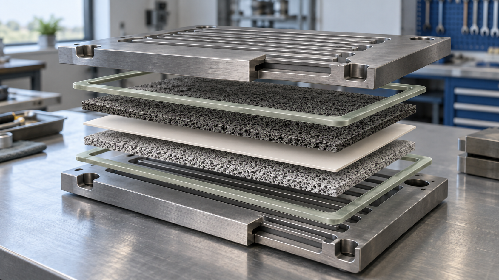
View the original SVG schematic with technical details
- Electrolyte: ORNL says zirconia-based compositions are commonly applied as SOFC electrolytesSourced. The standard example is yttria-stabilised zirconia (YSZ). For materials in general, see also Jacobson's review "Materials for Solid Oxide Fuel Cells" [Ref. 8]
- Anode: a nickel-YSZ composite (Ni-YSZ, made from NiO-YSZ) is the standardSourced (Redox Power Systems report)
- Cathode: the most common materials are the perovskites La-Sr-Co-Fe oxide (LSCF) and La-Sr-Mn oxide (LSM)Sourced (review by Harrison et al.)
- Interconnect: the part that links cells. Ferritic stainless steel is used, sometimes with a zirconia or alumina coating on its surfaceSourced (ORNL)
3. Our calculation: the heating-value basis, and household efficiency
Osaka Gas's household SOFC "ENE-FARM Type S" (announced 2020) has a rated electric efficiency of 55% (LHV), and 49.6% when the same product is expressed on a higher heating value (HHV) basis. Overall efficiency is 87% (LHV) and 78.5% (HHV). Output is 50-700 W, fuel is city gas 13A or LP gas, and the power generation unit's service life was extended from 10 to 12 yearsSourced (manufacturer's stated values).
- Converting the basis: 49.6 / 55 = 0.90. On a higher-heating-value basis the figure is about 10% smaller (the difference is whether the condensation heat of water vapour is counted)
- Fuel input (assuming a rated output of 700 W): 700 / 0.55 = about 1.27 kW (LHV)
- Recovered heat: at an overall efficiency of 87%, useful heat plus electricity is 1.27 × 0.87 = about 1.11 kW, so heat is 1.11 − 0.70 = about 0.41 kW
Assumptions and limits: the 700 W rated output is an assumption (the specification says 50-700 W). The 55% electric efficiency was observed in continuous, stable rated operation for three hours or more; otherwise the rated figure is 54% (overall 87%)Sourced. To compare efficiencies, the basis (LHV or HHV) and the operating conditions must be matched.
4. A materials engineer's view (1): the anode — nickel is the catalyst and also the weak point
In the Ni-YSZ anode, nickel acts as the catalyst for oxidising hydrogen and as the electron path, while YSZ gives the skeleton and the ion path. It avoids precious metals, but if the metal is exposed to air and re-oxidised, the volume change breaks the structure. The Redox Power Systems report says that of all the reliability issues for SOFCs, the main limitation for Ni-based cermet anodes (such as NiO-YSZ) is poor stability during reduction-oxidation (redox) cyclingSourced. Faes et al. likewise say state-of-the-art nickel-based anode-supported cells are highly sensitive to re-oxidation of the metal phase at the temperature of useSourced.
In other words, an operating accident such as a fuel cut-off or air ingress becomes direct damage to the material (this article's commentary).
- Degradation mechanisms (anode): the Redox Power Systems report lists, as mechanisms originating in cell components, coarsening of the microstructure, decomposition of materials, chemical reaction of electrode materials with the electrolyte at the interface, delamination, and for the anode coking and sulfur poisoningSourced
- A countermeasure: the project behind that report developed ceramic-anode cells based on the redox-stable conductive perovskite SrFe0.2Co0.4Mo0.4O3 (SFCM). It made 10 cm by 10 cm cells with a maximum power density of 0.9 W/cm² at 600 °C, assembled and demonstrated a 10-cell stack that performed similarly on reformed pipeline natural gas and hydrogen, and redox-cycled a 3-cell stack 40 times at about 600 °C without degradationSourced (laboratory and small-scale demonstration)
- Another approach: Faes et al. tested redox-stable Ni-YSZ anode-supported cells; a 55 cm² cell was mounted in a stack repeat element and tested over 40 full redox cyclesSourced
5. Cathode, interconnect and chromium poisoning
The cathode turns oxygen into oxide ions. The most common materials are LSCF and LSMSourced.
The cathode has a degradation of its own: chromium poisoning. According to the review by Harrison et al., chromium-containing species released from stack and system materials migrate to the cathode and react with the cathode material to form new phases. Those phases diminish catalytic and conductive performance and can even block the pathways through which oxygen must diffuse. Environmental factors such as temperature and humidity also affect the rate of degradationSourced.
The source is the interconnect's ferritic stainless steel. ORNL notes that zirconia or alumina coatings are applied to the steel's surfaceSourced. In addition, electrical contact layers sit between the interconnect and the electrodes to lower contact resistance. The review by Zhu et al. sorts the materials for the cathode-side layer into noble metals, conductive ceramics (perovskites, spinels and others) and compositesSourced.
6. A materials engineer's view (2): the seal — how glass ages over 40,000 hours
A planar SOFC stack needs seals to keep fuel and air from mixing. The ORNL report lists these requirements for seal materialsSourced.
- Electrically insulating
- Thermo-chemically stable in both fuel and oxidising environments
- Thermal expansion compatible with the other parts, such as electrodes, electrolyte and current collectors
- Durability on the scale of the stack's life, up to 40,000 hours
Typical seals are glass-ceramics that provide a rigid bond between components. Crystallisation-resistant glasses are leading candidates because they are self-healing and can relax thermal stresses by viscous flow at operating temperatureSourced.
ORNL deposited two commercial barium alkali silicate glasses (SCN and G6) on YSZ and alumina substrates and tested them at 800 °C in air and in steam + hydrogen + nitrogen for up to 40,000 hoursSourced.
- At the start: thermal expansion was in the range desired for an SOFC with a YSZ electrolyte and ferritic stainless steel interconnects, and both glasses wetted YSZ and alumina
- Interface reactions: at the SCN-YSZ interface a thin crystalline Ca-Ba-Si-O reaction layer appeared after 10,000 hours or longer; it grew slowly and acted as a barrier to interaction between glass and substrate. At the G6-YSZ interface a much thicker interdiffusion region formed, with a cubic-to-tetragonal-to-monoclinic ZrO2 transformation in the YSZ at the interface
- Crystallisation (devitrification): G6 resisted it much better than SCN. The steam + hydrogen + nitrogen environment led to less devitrification than air
- Pore coarsening: larger pores grew at the expense of smaller ones, and in the extreme case merged into a single pore that could threaten the seal's integrity. It was faster in the steam + hydrogen environment and on the alumina substrate
The report concludes that the glasses could provide adequate sealing for long-term operation, but that designers should account for the changes in properties that accompany microstructural changes after prolonged exposureSourced.
- 40,000 hours / 8,760 hours per year = about 4.6 years (continuous operation)
- The ORNL report also gives an expected SOFC service life of 10 to 15 years. 10-15 years is 87,600-131,400 calendar hours, so 40,000 hours is about 30-46% of that
Commentary: 40,000 hours is a measure of operating time, not of calendar years. How start/stop and idle time are counted changes the correspondence (this article's commentary).
7. Thermal cycling — start/stop damages materials
A high-temperature device swings widely in temperature at each start and stop. The ORNL report says seals must withstand temperature fluctuations between 800 °C and room temperature during on-off cyclesSourced. DOE says SOFCs start slowly and need thermal shielding to protect personnel, which may be acceptable for utility applications but not for transportationSourced.
Shin et al. studied the effect of ramp rate by cycling NiO-YSZ anode-supported cells between 400 and 700 °C (simulating periods, such as at night or in an emergency shutdown, when power is not needed). With ramp rates of 1, 2 and 5 °C/min, the voltage loss after 1,000 hours was 8.8% (82 µV per hour) at 1 °C/min and 19.1% (187 µV per hour) at 5 °C/min. The loss was mainly due to electrode degradation (increased polarisation resistance); the ohmic resistance did not change. With fast cycling there was severe agglomeration and depletion of nickel particles in the anode, the mean cathode particle size grew from 0.104 to 0.201 µm, and Sr-enriched regions were more prominentSourced (laboratory single cells).
- 82 µV/h × 1,000 h = 82 mV. If that is 8.8%, the initial voltage is 0.082 / 0.088 = about 0.93 V
- 187 µV/h × 1,000 h = 187 mV. If that is 19.1%, the initial voltage is 0.187 / 0.191 = about 0.98 V
Limit: the two values differ by rounding and by test conditions. These are laboratory single-cell results and do not give the degradation rate of a stack or a real system.
8. Stationary and data center use — what official sources confirm
SOFC products are used for household cogeneration and for commercial stationary power. This section sets out what official sources (company announcements and a U.S. annual report) confirm. All figures are companies' stated values, on different conditions, and none ranks any product or company.
| Product / company | What is published (company's stated values) | Conditions and date | Source |
|---|---|---|---|
| Osaka Gas ENE-FARM Type S (household) | Rated electric efficiency 55% (LHV) / 49.6% (HHV); overall 87% (LHV) / 78.5% (HHV). Output 50-700 W. Fuel city gas 13A or LP gas. Power unit life extended from 10 to 12 years. Width reduced from 780 mm to 600 mm and installation area cut by about 20%. Osaka Gas's cumulative sales of ENE-FARM units (all models, including Type S) reached 200,000 on 5 April 2024 | Announced 25 February 2020 (on sale April 2020). Electric efficiency was observed in continuous, stable rated operation for 3 hours or more; otherwise rated 54% (overall 87%) | [Refs. 10, 11] |
| Bloom Energy (commercial stationary power) | The Energy Server is a proprietary high-temperature solid oxide fuel cell that converts natural gas, biogas and hydrogen into electricity without combustion. Deployed at about 1,100 sites in 9 countries. A supply agreement under which AEP is expected to procure up to 1 GW of solid oxide fuel cells for uses such as AI data centers (announced November 2024; initial order 100 MW). A partnership with Oracle (October 2025) to provide on-site power for AI data centers. A financing framework with Brookfield of up to US$5.0 billion over five years (August 2025) | Form 10-K for the fiscal year ended 31 December 2025, filed 9 February 2026. Expansion of the AEP agreement (to 1 GW): Not yet confirmed | [Ref. 12] |
All Sourced (each company's official material). They are company statements; this article did not confirm independent verification.
Bloom Energy's 2025 Form 10-K describes a US$4.2 million increase in product performance guarantee costs as "reflecting the effects of fleet degradation"Sourced. The filing also lists as a risk that business and results could be harmed if estimates of the useful life of products are inaccurate or performance warranties and guaranties are not metSourced.
In other words, material degradation such as anode agglomeration, chromium poisoning and seal ageing shows up directly in the accounts as warranty and replacement costs (this article's commentary).
9. What is still hard, and what could not be confirmed
- The actual operating temperature and cell or stack materials of each company's products: not confirmed in the official material from Osaka Gas or Bloom Energy. The materials in Fig. 1 are representative examples named in the sources
- Degradation rates (per 1,000 hours) and lifetimes of real systems: measured product values could not be confirmed. ORNL's "40,000 hours" and a service life of 10-15 years are test and expected values
- Specific values of YSZ conductivity and the optimum yttria content: not given, because values with stated conditions could not be confirmed in the primary sources consulted
- Efficiency and life figures in Bloom Energy's 10-K: within the 10-K consulted, specific values for electrical efficiency or life could not be confirmed
- Track record of hydrogen-only SOFC operation: the 10-K lists hydrogen as a fuel, but performance and experience on hydrogen alone were not confirmed
- Commercial and industrial SOFCs in Japan (other than the household Type S): not covered here
- Specific glass compositions and thermal expansion values for seals: the ORNL report speaks of a "desired range", but numbers are not given here
(1) Do not carry laboratory results over to real-system lifetimes
The voltage loss of Shin et al., the redox tests of Faes et al., the ceramic anode of Redox Power Systems and ORNL's glass tests are all laboratory results under set conditions. Real systems involve fuel impurities, temperature distribution and assembly stress.
(2) "High efficiency" changes meaning with the basis and the operating conditions
Beyond the LHV/HHV difference (Fig. 4), efficiency changes with whether it is at rated or part load, and with whether it is continuous operation or includes start/stop.
- A SOFC is a high-temperature fuel cell with a dense ceramic electrolyte. According to DOE it is about 60% efficient, over 85% with cogeneration, and needs no precious-metal catalystSourced
- Lifetime is set by the "thermal compatibility" of materials. Nickel agglomeration and redox damage at the anode, chromium poisoning at the cathode, and ageing of the glass seal are the main degradation modesSourced
- ORNL tested glass seals at 800 °C for up to 40,000 hours and reported interface reaction layers, crystallisation and pore coarseningSourced
- Faster heating and cooling does more damage. In laboratory single cells, voltage loss after 1,000 hours was 8.8% (1 °C/min) and 19.1% (5 °C/min)Sourced
- A household unit's rated efficiency of 55% (LHV) is 49.6% (HHV); the basis alone shifts the number by about 10%Our calculation
10. Glossary
- SOFC (solid oxide fuel cell)
- A high-temperature fuel cell (hundreds of degrees up to about 1,000 °C) whose electrolyte is a ceramic that passes oxide ions.
- YSZ (yttria-stabilised zirconia)
- Zirconia with yttria added to stabilise the cubic phase. The standard SOFC electrolyte.
- Ni-YSZ
- A composite (cermet) of nickel and YSZ. The standard anode.
- LSM / LSCF
- Perovskites used as cathodes: La-Sr-Mn oxide and La-Sr-Co-Fe oxide.
- Interconnect
- The part that links cells in series and separates fuel from air. Ferritic stainless steel and similar materials are used.
- Chromium poisoning
- Chromium released from steel migrates to the cathode, reacts, and degrades performance.
- Redox (reduction-oxidation)
- Oxidation of the anode's nickel, for example when fuel is cut off, followed by reduction again. It damages the structure.
- Coking
- Deposition of carbon on the anode, which degrades performance.
- Glass-ceramic seal
- A sealing material based on glass. It flows at high temperature to relieve stress, but changes through crystallisation and reactions.
- Devitrification
- Crystals forming in glass at high temperature, changing its properties.
- LHV / HHV
- Lower / higher heating value: without / with the condensation heat of water vapour.
- Cogeneration (CHP)
- Using waste heat, for hot water for example, while generating electricity.
11. References
- U.S. Department of Energy (DOE) "Types of Fuel Cells" — https://www.energy.gov/eere/fuelcells/types-fuel-cells
- R. Trejo et al. (ORNL) "Reliability of Materials and Components for Solid Oxide Fuel Cells", ORNL/LTR-2023/3073, March 2024 — https://www.osti.gov/biblio/2429858
- B. Blackburn, S. Deaconu et al. (Redox Power Systems) "Red-Ox Robust SOFC Stacks for Affordable, Reliable Distributed Generation Power Systems", 2022 (final report of a DOE project) — https://www.osti.gov/biblio/1882509
- Faes et al. "Redox stable Ni-YSZ anode support in solid oxide fuel cell stack configuration", Journal of Power Sources, 196, 3553-3558, 2011 — https://doi.org/10.1016/j.jpowsour.2010.11.047
- Harrison, Slater and Steinberger-Wilckens "A review of Solid Oxide Fuel Cell cathode materials with respect to their resistance to the effects of chromium poisoning", Solid State Ionics, 354, 115410, 2020 — https://doi.org/10.1016/j.ssi.2020.115410
- J. H. Zhu and H. Ghezel-Ayagh "Cathode-side electrical contact and contact materials for solid oxide fuel cell stacking: A review", International Journal of Hydrogen Energy, 2017 — https://www.osti.gov/biblio/1533888
- Shin, Saqib, Jo, Park, Park and Ahn "Degradation Mechanisms of Solid Oxide Fuel Cells under Various Thermal Cycling Conditions", ACS Applied Materials & Interfaces, 13, 49868-49878, 2021 — https://doi.org/10.1021/acsami.1c13779
- A. J. Jacobson "Materials for Solid Oxide Fuel Cells", Chemistry of Materials, 22, 660-674, 2010 — https://doi.org/10.1021/cm902640j
- Gong et al. "Materials system for intermediate temperature (600-800 °C) solid oxide fuel cells based on doped lanthanum-gallate electrolyte", ECS Proceedings Volumes, 2005 — https://doi.org/10.1149/200507.0419pv
- Osaka Gas "Osaka Gas to Release a New Product of ENE-FARM Type S, Household Fuel Cells Characterized by the Highest Power Generation Efficiency in the World and Improved Installation due to Significant Downsizing", 25 February 2020 (PDF) — https://www.osakagas.co.jp/en/whatsnew/__icsFiles/afieldfile/2020/03/03/20200225.pdf
- Osaka Gas "Osaka Gas Sold a Total of 200,000 Units of the Ene-Farm Fuel Cell System for Residential Use", 10 April 2024 (PDF) — https://www.osakagas.co.jp/en/whatsnew/__icsFiles/afieldfile/2024/05/10/240410.pdf
- Bloom Energy Corporation Form 10-K for the fiscal year ended 31 December 2025, filed 9 February 2026 (SEC EDGAR) — https://www.sec.gov/Archives/edgar/data/1664703/000162828026006516/be-20251231.htm
12. Claim-to-source audit
| Claim in the text | Basis | Category |
|---|---|---|
| That the SOFC uses a hard, dense ceramic electrolyte; efficiency of about 60% and over 85% in cogeneration; operation at up to about 1,000 °C; no need for a precious-metal catalyst; internal reforming of fuel; sulfur tolerance; no CO poisoning and CO usable as fuel; slow start-up and the need for thermal shielding; that low-cost durable materials are the key challenge; and that SOFCs at or below 700 °C are being explored | DOE, "Types of Fuel Cells"Reference 1 https://www.energy.gov/eere/fuelcells/types-fuel-cells | Sourced |
| That zirconia-based compositions are used as electrolytes and that zirconia and alumina coatings go on ferritic stainless steel interconnects; the requirements for seals (insulating, stable in fuel and oxidising environments, expansion compatibility, 40,000 hours); glass-ceramics and crystallisation-resistant glasses; the results of the 800 °C tests up to 40,000 hours on glasses SCN and G6 (expansion in range, Ca-Ba-Si-O reaction layer, G6/YSZ interdiffusion and ZrO2 phase change, devitrification, pore coarsening); temperature fluctuations between 800 °C and room temperature; and the expected service life of 10-15 years | ORNL report (ORNL/LTR-2023/3073, March 2024)Reference 2 https://www.osti.gov/biblio/2429858 | Sourced |
| NiO-YSZ as an example anode; redox stability as the main limitation of Ni-based cermet anodes; degradation mechanisms of cell components (coarsening, decomposition, interface reactions, delamination, coking, sulfur poisoning); the SFCM ceramic anode: 10 cm by 10 cm cells, maximum power density of 0.9 W/cm² at 600 °C, a 10-cell stack, and 40 redox cycles of a 3-cell stack without degradation | Redox Power Systems (final report of a DOE project, 2022)Reference 3 https://www.osti.gov/biblio/1882509 | Sourced |
| That state-of-the-art nickel-based anode-supported cells are highly sensitive to re-oxidation; and the testing of redox-stable Ni-YSZ anode-supported cells over 40 redox cycles with a 55 cm² cell | Faes et al. (J. Power Sources, 2011)Reference 4 https://doi.org/10.1016/j.jpowsour.2010.11.047 | Sourced |
| That LSCF and LSM are the most common cathode materials; chromium poisoning (chromium species migrating to the cathode, forming new phases, reducing catalytic and conductive performance, blocking oxygen pathways); and the effects of temperature and humidity | Harrison et al. (Solid State Ionics, 2020)Reference 5 https://doi.org/10.1016/j.ssi.2020.115410 | Sourced |
| The materials for the cathode-side electrical contact layer (noble metals, conductive ceramics, composites) | Zhu and Ghezel-Ayagh (IJHE, 2017)Reference 6 https://www.osti.gov/biblio/1533888 | Sourced |
| The thermal cycling tests of NiO-YSZ anode-supported cells between 400 and 700 °C (1, 2 and 5 °C/min, 1,000 hours): voltage losses of 8.8% (82 µV/h) and 19.1% (187 µV/h), electrode degradation as the main cause, nickel agglomeration and depletion, cathode particle size from 0.104 to 0.201 µm, and Sr-enriched regions | Shin et al. (ACS Appl. Mater. Interfaces, 2021)Reference 7 https://doi.org/10.1021/acsami.1c13779 | Sourced |
| A review of materials for SOFCs (title only referenced); a study of a materials system for intermediate-temperature (600-800 °C) SOFCs (title only referenced) | Jacobson (2010), Gong et al. (2005)Reference 8 https://doi.org/10.1021/cm902640jReference 9 https://doi.org/10.1149/200507.0419pv | Sourced |
| ENE-FARM Type S: rated electric efficiency 55% (LHV) / 49.6% (HHV), overall 87% (LHV) / 78.5% (HHV), output 50-700 W, life 10 to 12 years, width 780 to 600 mm, about 20% less installation area, fuels (city gas 13A, LP gas), the efficiency conditions (3 hours or more of continuous, stable rated operation; otherwise 54%, overall 87%), and Osaka Gas's cumulative ENE-FARM sales of 200,000 units (5 April 2024) | Osaka Gas news releases (25 February 2020, 10 April 2024)Reference 10 https://www.osakagas.co.jp/en/whatsnew/__icsFiles/afieldfile/2020/03/03/20200225.pdfReference 11 https://www.osakagas.co.jp/en/whatsnew/__icsFiles/afieldfile/2024/05/10/240410.pdf | Sourced |
| Bloom Energy's high-temperature solid oxide fuel cell, its fuels (natural gas, biogas, hydrogen), about 1,100 sites in 9 countries; the AEP agreement for up to 1 GW with an initial 100 MW; the Oracle partnership (October 2025) and the Brookfield framework of up to US$5.0 billion (August 2025); the US$4.2 million increase in performance guarantee costs reflecting fleet degradation; and the risk language on useful life and warranties | Bloom Energy Form 10-K (FY2025)Reference 12 https://www.sec.gov/Archives/edgar/data/1664703/000162828026006516/be-20251231.htm | Sourced |
| 49.6 / 55 = 0.90; a fuel input of about 1.27 kW (LHV) at an assumed 700 W rating; recovered heat of about 0.41 kW; 40,000 h / 8,760 = about 4.6 years, and 30-46% of 87,600-131,400 calendar hours; and the initial voltages read from the loss ratios (about 0.93 V and 0.98 V) | Our calculation. Assumptions: rated output 700 W (the specification says 50-700 W), overall efficiency 87% (LHV), continuous operation, and that the loss ratio and the hourly loss refer to the same reference voltage in the same test. Not values for a real system | Our calculation |
| The expansion of the AEP agreement to 1 GW (the initial order is 100 MW) | A company announcement, not a result; an outlookReference 12 https://www.sec.gov/Archives/edgar/data/1664703/000162828026006516/be-20251231.htm | Not yet confirmed |
| The actual operating temperature and cell/stack materials of each company's products, degradation rates and lifetimes of real systems, YSZ conductivity values, efficiency and life figures in the 10-K, the track record on hydrogen alone, commercial and industrial SOFCs in Japan, and specific glass compositions and expansion values | Could not be confirmed in primary sources within the scope of this article, so not described. This article's commentary | Commentary |
| The reading that thermal compatibility between ceramics and metals sets lifetime; that operating accidents at the anode become material damage; that the seal glass flows and changes at 800 °C; the caution that 40,000 hours is not calendar years; and the reading that material degradation shows up as warranty and replacement cost | This article's summary and commentary based on published content. Not views stated by the institutions concerned | Commentary |
| That Figs. 1 to 4 are explanatory drawings rather than real cross-sections, micrographs or test records, and that Fig. 5 and the hero image are AI-generated images | Our note | Commentary |
Last updated 8 October 2026. Sources are limited to primary material (government and national laboratory reports, official company announcements and annual reports, and peer-reviewed papers). Company values are labelled as the company's stated values. Because the article includes structural readings and materials-design interpretations, those are marked as Commentary and kept separate from sourced fact. The actual operating temperature and materials of each company's products, degradation rates and lifetimes of real systems, YSZ conductivity values and a record of hydrogen-only operation are not stated here because no primary source could be confirmed. Laboratory single-cell results do not give the degradation rate of a stack or a real system. The handling of hydrogen and flammable gases is governed by law and standards. This article is an explanation, not advice on design, operation or handling. All figures are explanatory concept graphics. Figs. 1 to 4 are vector drawings; Fig. 5 and the hero image are AI-generated images, and none of them shows a real cross-section, micrograph or physical equipment.