TECHNOLOGY EXPLAINER
Solid Oxide Electrolysis Cells (SOEC)
— ceramics at 800 °C that let heat stand in for part of the electricity
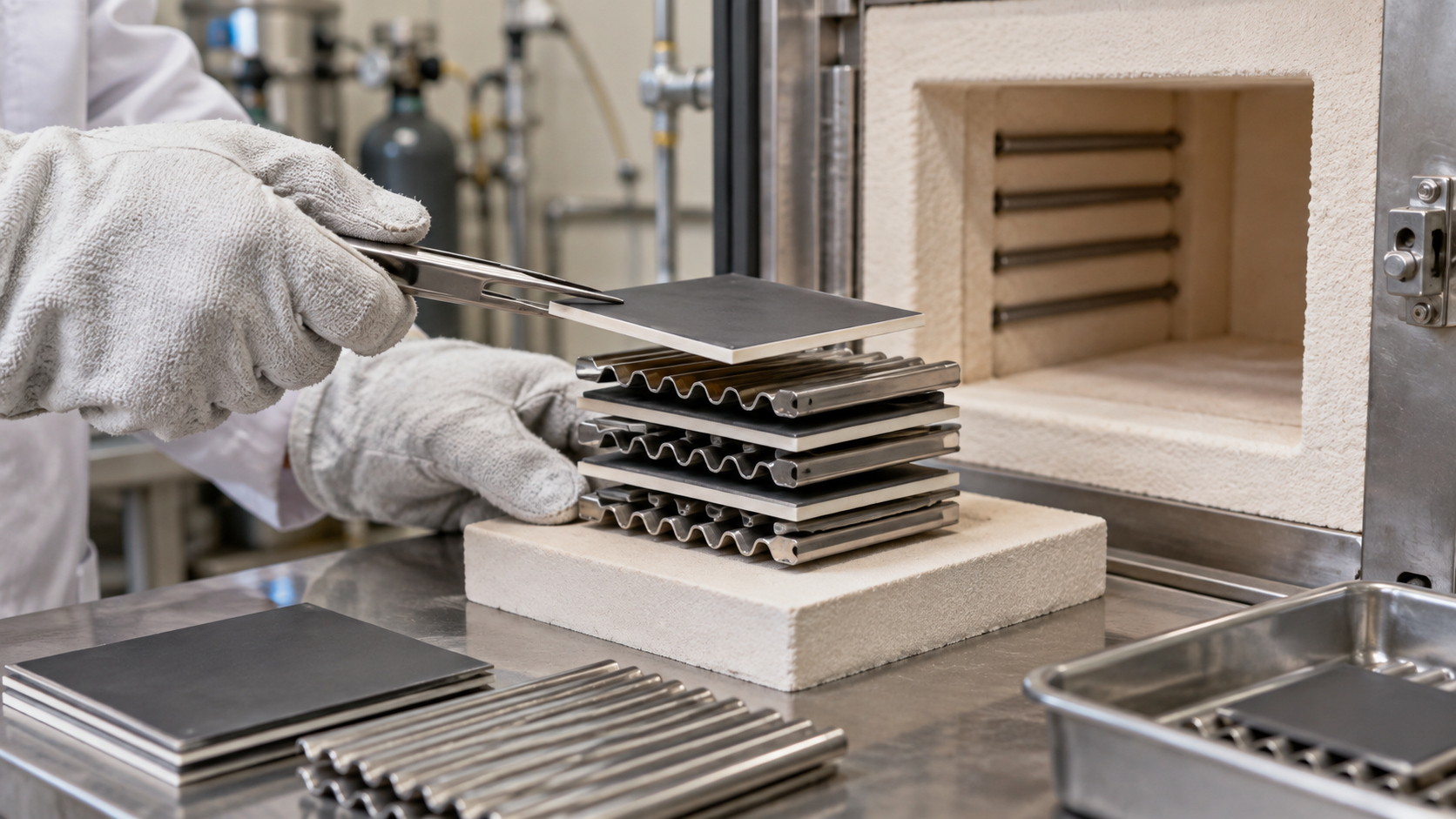
A solid oxide electrolysis cell (SOEC) splits steam at about 700–850 °C. It uses a ceramic electrolyte such as YSZ (yttria-stabilised zirconia), and the faster kinetics and favourable thermodynamics at high temperature can cut electricity use. But how its efficiency reads depends on where the heat comes from, and life depends on whether the parts survive repeated heating and cooling (thermal cycling and seals). This article lays out the materials and how to read the numbers.
- What a solid oxide electrolysis cell is (the short version)
- Reactions and cell structure
- What high temperature buys — heat covering part of the electricity
- A materials engineer’s view (1): the YSZ electrolyte — a ceramic that passes oxide ions
- Electrodes and parts in combination — nickel, perovskites, chromium
- A materials engineer’s view (2): thermal cycling and seals
- Reading efficiency — the link to the heat source
- Track record — separating demonstration, products and plans
- Reading the numbers, evaluation and standards
- Challenges and limits / Glossary / Primary sources / Claim-to-source audit
Sourced = a value or statement in published material (link given)
Our calculation = a figure this article derived, with the assumptions spelled out
Not yet confirmed = a plan, target or expected value with no confirmed result
Structural readings and materials-design interpretations are marked separately as Commentary.
Performance figures are given together with the level they apply to (single cell, stack or system; temperature; current density; treatment of heat) and their status (laboratory, demonstration, commercial or target). Manufacturers’ values are marked as the manufacturer’s.
Hydrogen is a flammable gas, and its handling is governed by laws and standards. This article explains materials, principles, evaluation and policy; it is not advice on handling or operating hydrogen or high-temperature equipment. It does not rank any product, company or country.
1. What a solid oxide electrolysis cell is (the short version)
SOEC stands for solid oxide electrolysis cell. It is a way of electrolysing high-temperature steam through a ceramic electrolyte that passes oxide ions (O²⁻).
- It works hot: in IRENA’s 2020 table the operating temperature is 700–850 °C at about 1 barSourced. Brauns and Turek describe SOEL (solid oxide electrolysis) as splitting steam into hydrogen and oxygen at 700–900 °CSourced
- It may use less electricity: the review by Hauch et al. (Science, 2020) says the high operating temperature of SOECs brings favourable thermodynamics and reaction kinetics and enables conversion efficiencies not matched by other electrolysis technologiesSourced. IRENA likewise says electricity demand falls and part of the separation energy is supplied as heat, so that apparent efficiency based on electricity alone can exceed 100%Sourced
- The price: IRENA says that, because of the high temperature, thermal cycling (especially in shutdown and ramping) speeds degradation and shortens life. In 2020 it described SOECs as deployed only at kW scale, with some demonstrations reaching 1 MWSourced
An SOEC’s “high efficiency” is a figure for electricity only. The heat to make steam and to hold 800 °C is needed separately, and where it comes from (waste heat or electricity) changes the apparent advantage a great deal. Always check whether heat has been counted (our commentary; Chapter 7).
How SOEC differs from PEM, alkaline and AEM is covered in our explainers on PEM, alkaline and AEM water electrolysis. The solid oxide fuel cell has its own explainer; for the sintering and grain-boundary problems of ceramic electrolytes, our explainer on oxide solid electrolytes in the all-solid-state battery series is also relevant.
2. Reactions and cell structure
At the fuel electrode steam splits into hydrogen and oxide ions; the oxide ions cross the electrolyte to the air electrode, where they become oxygen (the reactions are textbook material, our commentary). In electrolysis the SOEC’s fuel electrode is the cathode, but we use the fuel-cell name, “fuel electrode”, common to both modes.
| Part | Example material | Role | Materials difficulty |
|---|---|---|---|
| Electrolyte | YSZ (yttria-stabilised zirconia) | Passes O²⁻, blocks gas and electrons | Must be dense; conduction is too low unless hot |
| Fuel electrode (hydrogen electrode) | Ni/YSZ (a nickel–YSZ cermet) | Splits steam | Nickel coarsening and migration; expansion on oxidation |
| Air electrode (oxygen electrode) | Perovskite-type oxides (LSCF, LSM and others) | Turns O²⁻ into oxygen | Reaction with the electrolyte (insulating phases); chromium poisoning |
| Interconnect | Stainless steel (example: Crofer 22 APU with a cobalt-containing protective coating) | Joins cells and separates the gases | Chromium evaporation; oxide-scale growth |
| Seals | Glass-based ceramic (IRENA’s “Ceramic glass”) | Keep gas in | Differential pressure, thermal cycling, silica contamination |
All Sourced (IRENA [Source 1] Table 1, review by Dragan [Source 3]). The “Role” column is our commentary. IRENA notes that for AEM and solid oxide, conditions and components vary significantly between companies and research institutes.
3. What high temperature buys — heat covering part of the electricity
The total energy needed to split water is the sum of electricity and heat. The higher the temperature, the faster the reaction, the less electricity has to be supplied and the more is supplied as heat. IRENA lists the advantages of high temperature as favourable kinetics that allow relatively cheap nickel electrodes, lower electricity demand with part of the separation energy supplied as heat (waste heat included), the potential for reversible operation as a fuel cell, and co-electrolysis of CO₂ and water to produce syngasSourced. Brauns and Turek say that stack efficiencies near 100% are theoretically possible, but that the extra heat demand needs a waste-heat source from the chemical, metallurgical or thermal power industrySourced.
DOE’s table for high-temperature electrolyzer stacks sets its performance reference at 1.28 V per cell and gives an electrical efficiency of 34 kWh/kg (98% LHV)Sourced. Applying the conversion in our explainer on PEM water electrolysis (kWh/kg = cell voltage × 26.59), 1.28 × 26.59 = 34.0 kWh/kg, and 33.3 ÷ 34.0 = about 97.9% on an LHV basisOur calculation, consistent with DOE.
Assumptions and limits: 100% current efficiency and a lower heating value of 33.3 kWh/kg are assumptions set by this article. 1.28 V can be read as a voltage near the “thermoneutral” point for splitting steam electrically (our commentary). This is an electrical stack figure; it excludes the heat to make steam and system losses. The basis differs from low-temperature electrolysis, where 1.48 V is the thermoneutral voltage for PEM.
4. A materials engineer’s view (1): the YSZ electrolyte — a ceramic that passes oxide ions
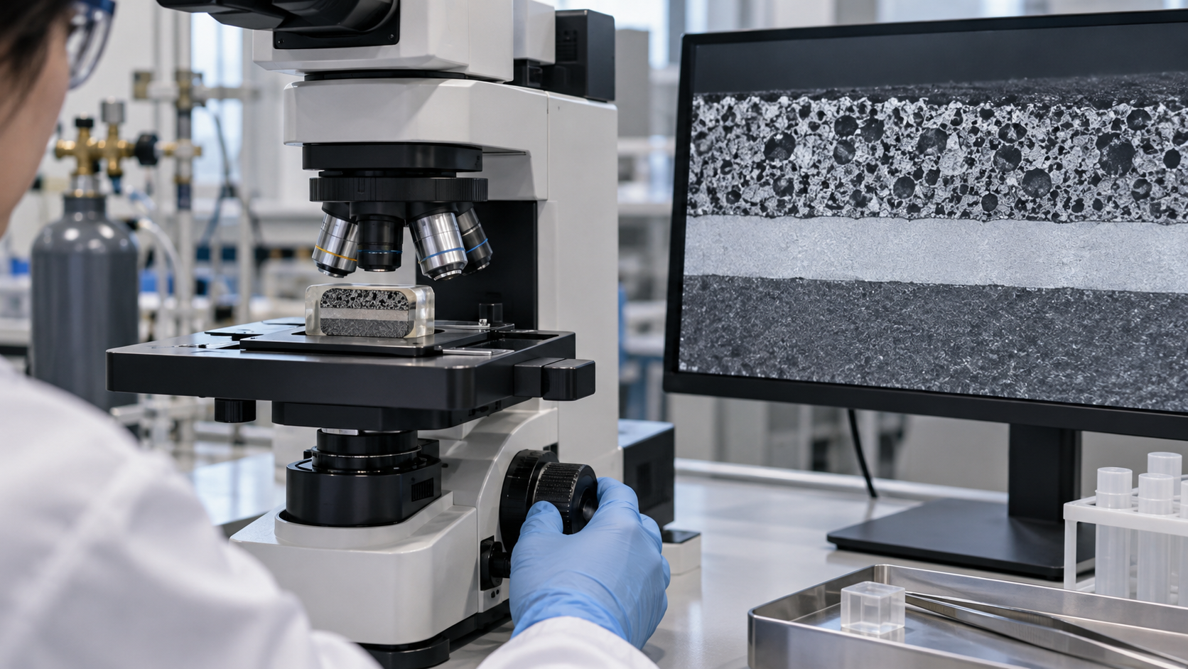
The standard SOEC electrolyte is YSZ: zirconia (ZrO₂) stabilised with yttria (Y₂O₃) and the like. The review by Dragan describes the Zr–Y pairing as the staple of zirconia electrolytes, with yttrium, scandium or magnesium added to stabilise the structure and raise conductivity, and notes growing interest in ceria-based materials such as gadolinium-doped ceria (GDC), which offer higher ionic conductivity at intermediate temperaturesSourced.
- The ion: the LLZO and similar materials in our explainer on oxide solid electrolytes pass lithium ions; YSZ passes oxide ions (the explanation that YSZ conducts through oxygen vacancies is our commentary).
- Phase stability: zirconia can transform from cubic to tetragonal, which depends strongly on the Y₂O₃ concentration, says the same reviewSourced. The amount added is a trade between conductivity and phase stability (our commentary).
- A shared difficulty: as that oxide-electrolyte explainer shows, the heart of ceramic-electrolyte design is sintering powder to density and keeping grain-boundary resistance down. In an SOEC too, an electrolyte that is not dense lets the gases mix (our commentary).
- What the temperature means: since YSZ needs high temperature for useful conduction, the 700–850 °C operating range follows (our reading of the operating temperature IRENA gives and the use of YSZ).
5. Electrodes and parts in combination — nickel, perovskites, chromium
IRENA’s table gives the fuel electrode as Ni/YSZ and the air electrode as a perovskite type (LSCF, LSM)Sourced. The review by Dragan says that the LSM/YSZ air electrode is reliable, technologically compatible with other components and effective above 850 °C, whereas LSCF, an iron-substituted La₁₋ₓSrₓCoO₃ (La₀.₆Sr₀.₄Co₀.₂Fe₀.₈O₃₋δ), is regarded as a material for the next generation of lower-temperature cellsSourced.
In the combination of materials, reactions between parts and volatile elements decide life.
- Interface reactions: chemical reactions between the electrolyte and the air electrode form insulating secondary phases in LSCF/YSZ, GDC/YSZ and LSCF/GDC combinations, says the review. Ni-YSZ on the fuel side, it adds, does not have problems with YSZSourced
- Changes in nickel: in Ni fuel electrodes the main microstructural changes are coarsening, migration and depletion of nickel, and coarsening is regarded as the most harmful degradation mechanism. In a comparison of two nominally identical cells run for 1000 h, only the cell in electrolysis mode showed significant nickel migration away from the electrolyte interface, the review reportsSourced
- Oxidation of nickel: if oxygen gets into the fuel electrode through a system leak or poorly controlled fuel utilisation, the nickel expands irreversibly, which starts cracking and delaminationSourced
- Chromium evaporation: chromium vapour from LaCrO₃-type interconnects contaminates the air electrode, blocking reaction sites and sharply lowering conductivity; and once chromium in the interconnect itself falls too low, oxidation runs awaySourced. In IRENA’s example the interconnect is Crofer 22 APU with a cobalt-containing protective coatingSourced
6. A materials engineer’s view (2): thermal cycling and seals
An SOEC stacks ceramics, cermet, metal and glass, each with a different coefficient of thermal expansion. The review by Dragan says that electrolyte, electrodes and interconnects must expand and contract at similar rates through heating and cooling, and that a mismatch in thermal expansion leads to mechanical failure by cracking and delaminationSourced. IRENA writes that SOECs can reach lifetimes of 20,000 hours under constant power and well-defined operating conditions (not coupled to variable renewable energy), but that the main degradation mechanism is thermal cycling, because the stack must be cooled in dynamic operationSourced.
- Time to cool and reheat: in IRENA’s 2020 summary, a cold start to nominal load takes over 600 minutes (target under 300)Sourced.
- Reversible operation: IRENA says reversible operation (electrolysis plus fuel cell) could help by increasing hours of operation and keeping the system at temperature. A footnote at the same place says that reversible operation also compromises durabilitySourced.
- Larger cells: IRENA writes that deploying SOEC at large scale needs larger cells (from about 300 cm² to over 1,000 cm²), which are more prone to failureSourced.
- Seals: IRENA lists sealing at higher differential pressure, electrode contamination by silica used in sealants, and other contaminant sources from piping, interconnects and sealingSourced.
An SOEC thus suits uses where it can run steadily at constant output without being stopped (a site with usable waste heat, continuous operation); for following variable renewable power, the materials challenges come to the fore (our commentary). Sunfire’s latest-generation product page states an operating range of “50–100% and 10%/min” (manufacturer’s stated value; see below).
7. Reading efficiency — the link to the heat source
DOE’s technical-target table lists three kinds of efficiency for SOEC separatelySourced.
- Stack electrical efficiency: 34 kWh/kg (98% LHV), the same for the 2022 status and the targets (at 1.28 V)
- System electrical efficiency: 38 (88%) in 2022, 36 (93%) as the 2026 target and 35 (95%) kWh/kg as the ultimate target
- Energy efficiency: 47 (71%) in 2022, then 44 (76%) and 42 (79%) kWh/kg
The gap between “system electrical efficiency” and “energy efficiency” is 9 kWh/kg in the 2022 status, 8 for the 2026 target and 7 for the ultimate targetOur calculation. We have not confirmed an explicit definition of heat in the DOE table, but the gap can be read as energy other than electricity, such as the heat to make steam (our reading).
By comparison, in the same DOE tables the system electricity of PEM and alkaline is 55 kWh/kg in 2022. On electricity alone SOEC (38) uses about 31% less than PEM ((55 − 38) ÷ 55). Adding the heat (9) to reach 47, the saving shrinks to about 15% ((55 − 47) ÷ 55)Our calculation. If heat is nearly free waste heat the first figure applies; if it is supplied by electric heaters, the second comes closer (our commentary).
For SOEC the choice of numerator and denominator differs between sources. Check three things.
- Electricity only, or heat as well: Sunfire’s and Salzgitter’s “84% LHV, AC” is an efficiency against AC electricity, with steam raised from the steelworks’ waste heat (Sunfire’s page: “Steam generated by off-heat enables highest efficiency”)Sourced. Without that heat source the same number would not apply (our commentary).
- Which level: stack, system (with rectifier and steam generation) or plant.
- At what point in life: beginning or end of life. DOE defines end of life as a 10% voltage increaseSourced. Sunfire says efficiency and capacity are guaranteed through a long-term service agreement that includes stack replacementsSourced (manufacturer’s statement).
8. Track record — separating demonstration, products and plans
| Level | What is published | Source |
|---|---|---|
| Demonstration | GrInHy2.0 (Salzgitter, Germany; steelworks): Sunfire-HyLink SOEC, 720 kW, up to 18 kg/h of hydrogen, commissioned in 2020. In April 2022 it was announced that the unit produced 200 Nm³/h of hydrogen for the first time and showed an electrical efficiency of 84% (el, LHV). Operating temperature 850 °C, using waste heat from the steelworks. Salzgitter compares this with “around 60% (el, LHV)” for alkaline or PEM | Salzgitter AG (2022) [Source 8]; Sunfire case page [Source 9] (statements by the operator and manufacturer) |
| Commercial specification | Sunfire “HyLink SOEC” third generation (GEN 3): 10 MW module, net production rate 291 kg/h, operating range 50–100% (10%/min), hydrogen purity to ISO 14687 Grade B, and an efficiency of “89% LHV, AC” listed as an expected value (the 84% is noted as proven with GEN 1 in GrInHy2.0). Dated “As of 10 2024” and subject to change without notice. The company says SOEC is “25–30 %pt higher efficiency than low-temperature electrolysis” | Sunfire product page [Source 10] (manufacturer’s stated value, viewed 8 October 2026). The 89% is an expected valueNot yet confirmed |
| Overall scale | IRENA (2020) described SOEC as deployed only at kW scale, with some demonstrations reaching 1 MW. Brauns and Turek gave SOEL stack capacity in 2020 as below 10 kW (against 6 MW for AEL and 2 MW for PEMEL) | IRENA [Source 1], Brauns and Turek [Source 2] |
All Sourced (but statements by companies and operators). The 89% is the product page’s expected value; the demonstrated value is 84% (GEN 1, using waste heat). Measured degradation rates and lifetimes could not be confirmed from primary sources within the scope of this article.
Our calculation
- GrInHy2.0: 200 Nm³/h × 0.08988 kg/Nm³ = 18.0 kg/h (matches “up to 18 kg/h” on the case page). From 84% LHV, 33.3 ÷ 0.84 = about 39.6 kWh/kg (AC). 18 kg/h × 39.6 = about 713 kW, consistent with the stated 720 kW
- HyLink SOEC GEN 3: from 89% LHV, 33.3 ÷ 0.89 = about 37.4 kWh/kg. 291 kg/h × 37.4 = about 10.9 MW, some 9% above the “10 MW module”. The page does not let us tell whether 10 MW is a nominal designation or the operating point differs
Assumptions and limits: a hydrogen density of 0.08988 kg/Nm³ (0 °C, 1 atm) and an LHV of 33.3 kWh/kg are assumptions set by this article. Whether “84%” and “89%” are values at rated operation, and how the heat for steam is treated, are limited to what the sources let us confirm.
9. Reading the numbers, evaluation and standards
| Item | DOE high-temperature electrolysis (2022 status → 2026 target → ultimate target) | IRENA summary (December 2020) | Sunfire and Salzgitter (demonstration; manufacturer’s statements) |
|---|---|---|---|
| What the number is | A status and targets for stack and system. Targets must be met together; electricity at or below 0.03 $/kWh and availability above 90% assumed | A summary of the 2020 situation | The result of the demonstration (720 kW) and a product-page specification |
| Current density and voltage | 0.6 → 1.2 → 2.0 A/cm² at 1.28 V | Nominal current density 0.3–1 A/cm², voltage range 1.0–1.5 V | Not stated |
| Electricity use and efficiency | Stack 34 kWh/kg (98% LHV). System electrical 38 → 36 → 35, energy 47 → 44 → 42 kWh/kg | Stack 35–50, system 40–50 kWh/kg, voltage efficiency (LHV) 75–85% | 84% LHV, AC (demonstration, using waste heat); 89% LHV, AC (expected for GEN 3) |
| Degradation and life | Degradation 6.4 → 3.2 → 1.6 mV/kh. Lifetime 20,000 → 40,000 → 80,000 h (end of life = 10% voltage increase) | Stack lifetime under 20,000 h; cold start over 600 min | Not stated (a long-term service agreement is cited as the guarantee) |
| Operating conditions | Not stated (a targets table) | 700–850 °C, pressure 1 bar, load range 30–125%, hydrogen purity 99.9% | 850 °C (GrInHy2.0). Operating range 50–100% (GEN 3) |
| Capital cost | Stack 300 → 125 → 50 $/kW; system (uninstalled) 2,500 → 500 → 200 $/kW | Stack over 2,000 $/kW (from 1 MW) | Not stated |
All Sourced (DOE [Source 4], IRENA [Source 1], Salzgitter and Sunfire [Sources 8–10]). Numbers differing in level, scope and treatment of heat are set side by side; this is not a ranking.
- A test standard for solid oxide cells: IEC 62282-8-101:2020, “Fuel cell technologies — Part 8-101: Energy storage systems using fuel cell modules in reverse mode — Test procedures for the performance of solid oxide single cells and stacks, including reversible operation” (published 18 February 2020, edition 1), covers performance tests of solid oxide cells and stacks in fuel cell mode, electrolysis mode and reversible operationSourced (IEC, checked 6 October 2026; the text is paid)
- The safety standard for electrolysers: ISO 22734:2019 has been withdrawn and replaced by ISO 22734-1:2025 (Part 1: Safety), published in July 2025. The old edition’s list of scopes (aqueous bases, aqueous acids, PEM, AEM) did not include solid oxideSourced (ISO, checked 5 October 2026). We have not checked how the new edition applies to solid oxide, as the text is paid
- Test protocols for low-temperature electrolysis: the JRC harmonised protocols (EUR 30752 EN, 2021) cover low-temperature electrolysis (PEM, AEM, alkaline) and do not include SOECSourced
10. Challenges and limits
(1) Measured degradation rates and lifetimes could not be confirmed
DOE’s table (a 2022 status of 6.4 mV/kh and 20,000 h) and IRENA’s summary (under 20,000 h) are both summaries and targets. Measured degradation rates and lifetimes of products could not be confirmed from primary sources within the scope of this article, so none is given.
(2) The treatment of heat differs between sources
Numbers such as 84% and 89% assume the heat for steam comes from waste heat. We could not confirm from the sources used here the efficiency when the heat is supplied by electricity. Nor have we confirmed the detailed definition of “energy efficiency” in the DOE table.
(3) Other companies’ products and plans are not covered
This article uses published material from Sunfire and Salzgitter as examples. Products and factories of Topsoe, Bloom Energy, Ceres Power, Chinese companies and others were not checked. No ranking of companies or products is made.
(4) What is not covered
Co-electrolysis with CO₂ (syngas), details of reversible operation, cell manufacturing (tape casting, sintering conditions), cost comparison, resource questions such as rare earths and zirconium, and the handling of hydrogen and high-temperature equipment are not covered.
- An SOEC electrolyses steam at about 700–850 °C through a ceramic YSZ electrolyteSourced
- At high temperature heat can cover part of the electricity, so apparent efficiency is high. DOE’s stack reference is 1.28 V and 34 kWh/kg (98% LHV)SourcedOur calculation
- Check whether heat is counted. In DOE’s 2022 table SOEC uses about 31% less than PEM on electricity alone, but about 15% less once heat is addedOur calculation
- The keys to life are thermal cycling, seals and interface reactions. IRENA gives 20,000 h for constant output under defined conditionsSourced
- The demonstration was 84% at 720 kW (using waste heat). The “89%” for the 10 MW module is an expected value on a product page.Not yet confirmed
11. Glossary
- SOEC / SOEL
- Solid oxide electrolysis cell / solid oxide electrolysis (high-temperature electrolysis).
- YSZ
- Yttria-stabilised zirconia: a ceramic electrolyte that passes oxide ions.
- Cermet
- A composite of ceramic and metal. Ni/YSZ is the standard example.
- Perovskite type
- The ABO₃ crystal structure to which air-electrode oxides such as LSCF and LSM belong.
- LSM / LSCF
- Lanthanum strontium manganite / an oxide containing cobalt and iron. Air-electrode materials.
- GDC
- Gadolinium-doped ceria: a ceria-based oxide-ion conductor.
- Interconnect
- A metal plate that joins cells and separates the fuel and air sides.
- Thermal cycling
- Repeated heating and cooling. Parts are damaged by differences in thermal expansion.
- Thermal expansion coefficient
- How much a material expands with temperature. The closer between layers, the less cracking.
- LHV
- Lower heating value: about 33.3 kWh per kg of hydrogen.
- ISO 14687
- The quality standard for hydrogen fuel, with grades such as Grade B.
- mV/kh
- Rise in cell voltage per 1000 hours: the unit of degradation rate.
12. Primary sources
- IRENA “Green hydrogen cost reduction: Scaling up electrolysers to meet the 1.5°C climate goal”, December 2020 (PDF) — irena.org
- Brauns J, Turek T “Alkaline Water Electrolysis Powered by Renewable Energy: A Review”, Processes 8(2), 248 (2020, peer-reviewed; cited here for its description of SOEL) — doi.org/10.3390/pr8020248
- Dragan M “Closing the Loop: Solid Oxide Fuel and Electrolysis Cells Materials for a Net-Zero Economy”, Materials 17(24), 6113 (2024, peer-reviewed review) — doi.org/10.3390/ma17246113
- U.S. Department of Energy (DOE) “Technical Targets for High Temperature Electrolyzer Stacks and Systems” (viewed 8 October 2026) — energy.gov
- U.S. Department of Energy (DOE) “Technical Targets for Proton Exchange Membrane Electrolysis” (viewed 5 October 2026) — energy.gov
- U.S. Department of Energy (DOE) “Technical Targets for Liquid Alkaline Electrolysis” (viewed 5 October 2026) — energy.gov
- Hauch A et al. “Recent advances in solid oxide cell technology for electrolysis”, Science 370(6513), eaba6118 (2020, peer-reviewed; abstract consulted) — doi.org/10.1126/science.aba6118
- Salzgitter AG “World’s Largest High-Temperature Electrolyzer Achieves Record Efficiency”, 19 April 2022 — salzgitter-ag.com
- Sunfire “Salzgitter – World Record Efficiency of Sunfire’s High-Temperature Electrolyzer” case page (viewed 8 October 2026) — sunfire.de
- Sunfire “HyLink SOEC” product page (viewed 8 October 2026; the page is dated “As of 10 2024”) — sunfire.de
- IEC “IEC 62282-8-101:2020 Fuel cell technologies — Part 8-101: Energy storage systems using fuel cell modules in reverse mode — Test procedures for the performance of solid oxide single cells and stacks, including reversible operation” — webstore.iec.ch
- ISO “ISO 22734-1:2025 Hydrogen generators using water electrolysis — Part 1: Safety” — iso.org
- ISO “ISO 22734:2019 Hydrogen generators using water electrolysis — Industrial, commercial, and residential applications” (withdrawn) — iso.org
- European Commission JRC Tsotridis G, Pilenga A, “EU harmonised protocols for testing of low temperature water electrolysers”, EUR 30752 EN (2021) — publications.jrc.ec.europa.eu
13. Claim-to-source audit
| Claim in the text | Basis | Label |
|---|---|---|
| That SOEC operates at 700–850 °C and about 1 bar. The table materials (YSZ electrolyte, perovskite-type LSCF and LSM on the oxygen side, Ni/YSZ on the hydrogen side, an interconnect of Crofer 22 APU with a cobalt-containing protective coating, glass-based ceramic seals). The note that AEM and solid oxide entries vary widely between companies. The advantages of high temperature (fast kinetics allowing cheap nickel electrodes, lower electricity demand with part of the separation energy supplied as heat so that electricity-based apparent efficiency can exceed 100%, reversible operation, co-electrolysis). That thermal cycling is the main degradation and speeds it in shutdown and ramping. The sealing issues (higher differential pressure, silica contamination of electrodes, other contaminant sources such as piping). That lifetimes of 20,000 h are possible under constant power and defined conditions, the footnote that reversible operation compromises durability, that moving from about 300 cm² to over 1,000 cm² cells makes failure more likely, and that SOECs were deployed at kW scale with some demonstrations at 1 MW. The 2020 summary values (nominal current density 0.3–1 A/cm², voltage 1.0–1.5 V, load range 30–125%, hydrogen purity 99.9%, voltage efficiency (LHV) 75–85%, stack 35–50 and system 40–50 kWh/kg, lifetime under 20,000 h, cold start over 600 min, stack capital cost over 2,000 $/kW) | IRENA (December 2020)[Source 1] https://www.irena.org/-/media/Files/IRENA/Agency/Publication/2020/Dec/IRENA_Green_hydrogen_cost_2020.pdf | Sourced |
| That SOEL is a method splitting steam at 700–900 °C, that stack efficiencies near 100% are theoretically possible but a waste-heat source from the chemical, metallurgical or thermal power industry is needed for the extra heat demand, and that SOEL stack capacity in 2020 was below 10 kW (against 6 MW for AEL and 2 MW for PEMEL) | Brauns and Turek (2020, peer-reviewed)[Source 2] https://doi.org/10.3390/pr8020248 | Sourced |
| That material choice is governed by thermal expansion coefficient, mechanical stability, oxygen-ion conduction and chemical stability, and that a thermal expansion mismatch causes cracking and delamination. That yttrium, scandium or magnesium are added to zirconia to stabilise it and raise conductivity and that ceria-based materials such as GDC attract interest for higher conductivity at intermediate temperatures. That the cubic-to-tetragonal transformation depends on Y₂O₃ concentration. The reliability of the LSM/YSZ air electrode and its effectiveness above 850 °C, and LSCF (La₀.₆Sr₀.₄Co₀.₂Fe₀.₈O₃₋δ) as a candidate for the next generation of lower-temperature cells. That reactions between electrolyte and air electrode form insulating secondary phases in LSCF/YSZ, GDC/YSZ and LSCF/GDC, while Ni-YSZ has no problem with YSZ. Nickel coarsening, migration and depletion; the 1000 h comparison of two cells in which only the electrolysis-mode cell showed nickel migration from the electrolyte interface; irreversible nickel expansion when oxygen enters the fuel electrode, and the resulting cracking and delamination. Poisoning of the air electrode by chromium vapour, the loss of conductivity, and runaway oxidation as interconnect chromium is depleted | Review by Dragan (2024, Materials)[Source 3] https://doi.org/10.3390/ma17246113 | Sourced |
| Every item in DOE’s high-temperature electrolysis table (stack 0.6/1.2/2.0 A/cm² at 1.28 V, 34 kWh/kg (98% LHV), degradation 6.4/3.2/1.6 mV/kh, lifetime 20,000/40,000/80,000 h, stack 300/125/50 $/kW, system electrical 38/36/35 kWh/kg (88/93/95% LHV), energy 47/44/42 kWh/kg (71/76/79%), system 2,500/500/200 $/kW) and the conditions that targets be met together, electricity at or below 0.03 $/kWh, availability above 90% and end of life at a 10% voltage increase | U.S. DOE (viewed 8 October 2026)[Source 4] https://www.energy.gov/eere/fuelcells/technical-targets-high-temperature-electrolysis | Sourced |
| DOE’s PEM system electricity (55 kWh/kg in 2022, 51 in 2026, 46 ultimate) | U.S. DOE (viewed 5 October 2026)[Source 5] https://www.energy.gov/eere/fuelcells/technical-targets-proton-exchange-membrane-electrolysis | Sourced |
| DOE’s alkaline system electricity (55 kWh/kg in 2022, 52 in 2026, 48 ultimate) | U.S. DOE (viewed 5 October 2026)[Source 6] https://www.energy.gov/eere/fuelcells/technical-targets-liquid-alkaline-electrolysis | Sourced |
| That the high operating temperature of SOECs brings favourable thermodynamics and reaction kinetics and enables conversion efficiencies not matched by other electrolysis technologies, and that thermal integration with downstream chemical synthesis is possible | Hauch et al. (2020, Science, abstract)[Source 7] https://doi.org/10.1126/science.aba6118 | Sourced |
| GrInHy2.0: the announcement of 19 April 2022, 200 Nm³/h of hydrogen produced for the first time, electrical efficiency of 84% (el, LHV), operating temperature of 850 °C, use of waste heat from the steelworks, the comparison with about 60% (el, LHV) for alkaline or PEM, and EU funding (FCH 2 JU, grant agreement 826350) | Salzgitter AG press release (19 April 2022)[Source 8] https://www.salzgitter-ag.com/en/newsroom/press-releases/details/worlds-largest-high-temperature-electrolyzer-achieves-record-efficiency-19500.html | Sourced |
| Sunfire-HyLink SOEC 720 kW, up to 18 kg/h, commissioned in 2020, Salzgitter, “84% LHV/AC” as a world-record efficiency, and that steam generated from waste heat enables the highest efficiency | Sunfire case page (manufacturer’s statement, viewed 8 October 2026)[Source 9] https://sunfire.de/en/cases/salzgitter-world-record-efficiency-of-sunfires-high-temperature-electrolyzer/ | Sourced |
| HyLink SOEC GEN 3: a 10 MW module, a net production rate of 291 kg/h, an operating range of 50–100% at 10%/min, hydrogen purity to ISO 14687 Grade B, 89% LHV, AC as an expected value with 84% noted as proven with GEN 1 in GrInHy2.0, dated October 2024 and subject to change, efficiency and capacity guaranteed through a long-term service agreement including stack replacements, steam above 150 °C and operation at about 800 °C, and 25–30 percentage points higher efficiency than low-temperature electrolysis | Sunfire product page (manufacturer’s stated value, viewed 8 October 2026). The 89% is an expected value[Source 10] https://sunfire.de/en/products/sunfire-hylink-soec/ | Not yet confirmed |
| That IEC 62282-8-101:2020 covers performance tests of solid oxide cells and stacks in fuel cell mode, electrolysis mode and reversible operation, published on 18 February 2020 as edition 1 | IEC page (checked 6 October 2026)[Source 11] https://webstore.iec.ch/en/publication/33278 | Sourced |
| That ISO 22734:2019 was withdrawn and replaced by ISO 22734-1:2025 (Part 1: Safety, July 2025), and that the old edition’s list of scopes (aqueous bases, aqueous acids, PEM, AEM) did not include solid oxide | ISO pages (checked 5 October 2026)[Source 12] https://www.iso.org/standard/82766.html [Source 13] https://www.iso.org/standard/69212.html | Sourced |
| That the JRC report (EUR 30752 EN, 2021) covers low-temperature water electrolysis (PEM, AEM, alkaline) | JRC Publications Repository[Source 14] https://publications.jrc.ec.europa.eu/repository/handle/JRC122565 | Sourced |
| 1.28 × 26.59 = 34.0 kWh/kg and 33.3 ÷ 34.0 = about 97.9%. The gaps between electricity and energy (47 − 38 = 9, 44 − 36 = 8, 42 − 35 = 7 kWh/kg), (55 − 38) ÷ 55 = about 31%, (55 − 47) ÷ 55 = about 15%. 200 Nm³/h × 0.08988 = 18.0 kg/h, 33.3 ÷ 0.84 = about 39.6 kWh/kg, 18 kg/h × 39.6 = about 713 kW. 33.3 ÷ 0.89 = about 37.4 kWh/kg, 291 kg/h × 37.4 = about 10.9 MW (about 9% above the 10 MW module) | Our calculation. 100% current efficiency, an LHV of 33.3 kWh/kg and a hydrogen density of 0.08988 kg/Nm³ (0 °C, 1 atm) are assumptions set by this article. We have not confirmed an explicit definition of heat in the DOE table; reading the gap as heat is our interpretation | Our calculation |
| Measured degradation rates and lifetimes of products, efficiency when heat is supplied by electricity, the detailed definition of “energy efficiency” in DOE’s table, products and factories of other companies (Topsoe, Bloom Energy, Ceres Power and others), and how ISO 22734-1:2025 applies to solid oxide | Could not be confirmed from primary sources within the scope of this article, so none is stated | Commentary |
| The reactions. The drawing that heat covers part of the electricity at high temperature, reading 1.28 V as near thermoneutral, the difference in ion and the oxygen-vacancy explanation between YSZ and LLZO, the reading of YSZ and operating temperature, the framing “how many times it was cooled rather than how many hours”, the reading that SOEC suits constant-output operation, and the framing that the apparent advantage changes with whether heat is waste heat or electricity | Our summary and commentary based on published content. Not views expressed by any of the institutions | Commentary |
| That Fig. 2, Fig. 6, Fig. 5 and Fig. 3 are explanatory drawings rather than real design or measurement diagrams, and that Fig. 1 and Fig. 4 are AI-generated images | Our note | Commentary |
Last updated 8 October 2026. Sources are limited to primary material (official documents of international bodies, governments, standards bodies, manufacturers and operators, and peer-reviewed papers). Because the article includes structural readings and materials-design interpretations, those are marked as Commentary and kept separate from sourced fact. Measured degradation rates and lifetimes of products, efficiency when heat is supplied by electricity, and other companies’ products and factories could not be confirmed and are not stated. The table in Chapter 9 and Fig. 6 set side by side numbers of different level, scope and treatment of heat and are not a ranking. Fig. 2, Fig. 6, Fig. 5 and Fig. 3 are vector drawings and Fig. 1 and Fig. 4 are AI-generated images; none of them shows a real cross-section, equipment or product.