TECHNOLOGY EXPLAINER
Fuel Cell Vehicles and PEM Fuel Cells
— four materials (membrane, catalyst, diffusion layer, plate) tested by degradation and sub-zero temperatures
The heart of a fuel cell vehicle is a stack of polymer electrolyte fuel cells (PEFCs) that make electricity from hydrogen and air. Toyota's MIRAI uses a stack of 330 cells in series with a maximum output of 128 kW (manufacturer's stated value). It runs at only about 80 °C, but in return needs a platinum catalyst and a fluorinated polymer membrane. In DOE's 2020 record, system durability was an estimated 4,100 hours against a 5,000-hour target, and cost about US$50/kW against a US$40/kW target.
- What fuel cell vehicles and PEFCs are (the short version)
- The single cell — membrane, catalyst layers, diffusion layers, plates
- Our calculation: waste heat grows as cell voltage falls
- A materials engineer's view (1): the membrane — a fluorinated polymer that passes only protons
- Catalyst layers, diffusion layers and plates
- Degradation — catalyst dissolution and chemical attack on the membrane
- A materials engineer's view (2): start/stop and sub-zero temperatures hurt materials most
- Published specifications — manufacturers' stated values and conditions
- DOE targets and the distance to them
- The link to fluoropolymers and PFAS
- What is still hard, and what could not be confirmed
- Glossary / References / Claim-to-source audit
Sourced = a statement in published material (link given)
Our calculation = a figure this article derived, with the assumptions spelled out
Not yet confirmed = a plan or target with no confirmed record of delivery
Structural readings and materials-design interpretations are marked separately as Commentary.
Hydrogen is a flammable gas and its handling is governed by law and standards. This article explains materials, principles, evaluation and policy. It is not advice on the design, operation or handling of any vehicle or facility, and it does not rank any model or company.
1. What fuel cell vehicles and PEFCs are (the short version)
A fuel cell converts hydrogen's chemical energy directly into electricity by an electrochemical reaction, without burning it. A fuel cell electric vehicle (FCEV) sends hydrogen from its high-pressure tank and oxygen from the air to an onboard fuel cell stack, which generates power to turn the motor.
- How it works: DOE explains that a fuel cell has two electrodes around an electrolyte. At the anode a catalyst splits hydrogen molecules into protons and electrons; the electrons go through an external circuit and the protons through the electrolyte to the cathode, where they combine with oxygen and the electrons to form water and heatSourced
- What marks the PEFC: DOE says PEM fuel cells run at around 80 °C, which allows quick start and less wear on components, but need a noble-metal catalyst (typically platinum), which adds cost. They are used mainly for transport and suit cars, buses and heavy-duty trucksSourced
- In a real vehicle: the fuel cell stack of Toyota's MIRAI (model FCB130) is a polymer electrolyte type with 330 cells connected in series and a maximum output of 128 kW (manufacturer's stated value). Hydrogen is stored in three 70 MPa tanks (141 L in total)Sourced
A PEFC's performance is decided less while it runs than when it is stopped, frozen or exposed to high potential. The catalyst dissolves as potential rises, the membrane thins chemically, and below freezing the product water turns to ice. For a materials engineer, the PEFC is a durability problem: can four materials survive cycles of humidity, potential and temperature?
2. The single cell — membrane, catalyst layers, diffusion layers, plates
A PEFC single cell is a stack of several materials. DOE describes its core as the membrane electrode assembly (MEA): the membrane, catalyst layers and gas diffusion layers (GDLs). The parts that fit the MEA into a stack are the bipolar plates and the gasketsSourced.
A single cell gives under 1 V, so cells are stacked and connected in series to reach a usable voltage. According to DOE, a typical stack consists of hundreds of cellsSourced. From the MIRAI's 330 cells and maximum output of 128 kW (manufacturer's stated value), the average maximum output per cell is about 390 WOur calculation (128,000 / 330 = 388).
3. Our calculation: waste heat grows as cell voltage falls
A fuel cell turns part of hydrogen's energy into electricity and the rest into heat. The higher the cell voltage, the higher the efficiency; the lower the voltage, the more heat. DOE defines the stack's heat-rejection metric, Q/ΔT, with a formula that uses a reference voltage of 1.25 VSourced.
- Assumption: DOE's formula (reference voltage 1.25 V). On a lower-heating-value basis, cell efficiency = cell voltage / 1.25, and waste heat / electric power = (1.25 − voltage) / voltage
- Running at 0.8 V: efficiency 0.8/1.25 = 64%; waste heat (1.25−0.8)/0.8 = 0.56 times the electric power
- Running at 0.6 V: efficiency 0.6/1.25 = 48%; waste heat (1.25−0.6)/0.6 = 1.08 times the electric power
- Reproducing DOE's example: a 90 kW stack at 0.6 V with coolant leaving at 80 °C and ambient 40 °C gives Q/ΔT = 90 × 1.083 / 40 = about 2.4 kW/°C, matching the value in DOE's record (2.4)
Limit: an idealised calculation, not the efficiency or heat of a real system. What it shows is that the lower the cell voltage (the higher the output), the more sharply the heat the radiator must handle grows (this article's commentary).
- Assumptions: maximum output 128 kW (manufacturer's stated value) and 330 cells. Cell voltage is assumed to be 0.6 V (the rated-point voltage DOE used when assessing the 2017 MIRAI; not the actual value for the current FCB130)
- Stack voltage = 330 × 0.6 = 198 V; current = 128,000 / 198 = about 646 A
- Waste heat = 128 × 1.083 = about 139 kW (comparable to the electric output)
Limit: the values change a great deal if the rated-point voltage differs. The rated-point voltage, cell area and current density of the current MIRAI could not be confirmed in published material, so these are assumed numbers.
4. A materials engineer's view (1): the membrane — a fluorinated polymer that passes only protons
DOE describes the membrane as the key to the technology: it conducts only positively charged ions and blocks electrons, and other substances passing through would disrupt the reactionSourced. For vehicles the membrane is very thin, in some cases under 20 micronsSourced.
- To pass protons it needs water (the membrane must be moist). It should not pass gases (hydrogen and oxygen crossover must be low).
- Thinner lowers resistance but makes gas passage easier and the membrane mechanically weaker (this article's commentary).
- It swells and shrinks with every change in humidity, which causes mechanical fatigue, and at the same time is attacked chemically by radicals formed in operation.
That DOE's membrane targets split proton resistance, crossover, mechanical durability and chemical durability into separate metrics reflects these conflicts (this article's commentary).
The review by Kusoglu and Weber says perfluorinated sulfonic-acid (PFSA) ionomers, although studied for decades, show complex behaviour that keeps posing scientific challenges, and covers the link between physical and transport properties and structure, composite membranes, degradation and thin filmsSourced.
| Metric (membrane) | Unit | 2015 status (laboratory tests) | 2020 target |
|---|---|---|---|
| Proton resistance (80 °C, water partial pressure 25 kPa) | ohm cm² | 0.027 | 0.02 |
| Proton resistance (max operating temperature 120 °C, 40 kPa) | ohm cm² | 0.072 | 0.02 |
| Hydrogen crossover (maximum) | mA/cm² | 1.1 | 2 |
| Mechanical durability (cycles until H₂ crossover exceeds 15 mA/cm²) | cycles | 23,000 | 20,000 |
| Chemical durability (hours until crossover or 20% OCV loss) | hours | 742 | over 500 |
| Cost (500,000 systems a year) | US$/m² | 17 | 20 |
All Sourced (DOE, "Technical Targets for PEM Fuel Cell Components" [Ref. 4]). The status values rest on a 2015 report for a reinforced, chemically stabilised membrane from 3M (perfluoro imide acid, PFIA, type) and are laboratory values, not vehicle results. Proton resistance rises at lower water partial pressure and at higher temperature.
5. Catalyst layers, diffusion layers and plates
(1) The catalyst layer — the amount of platinum is a cost and resource issue
DOE's electrocatalyst target for the total platinum-group-metal (PGM) content is 0.125 g or less per kW of rated (gross) power. The 2015 status was 0.16 g/kW (a 3M report). The target for oxygen-reduction mass activity (0.9 V, iR-free) is 0.44 A/mg-PGM, against a 2015 status of over 0.5 A/mg. For PGM-free catalysts the status is 0.016 A/cm² at 0.9 V against a target of over 0.044 A/cm²Sourced.
DOE's 2020 record puts the PGM content of the 2017 MIRAI stack at about 0.3 g/kW (DOE's statement, citing a Toyota paper)Sourced.
- Assumption: a stack of 90 kW gross (the size DOE says is needed for 80 kW net). g/kW is per rated (gross) power
- 0.3 g/kW (the value DOE gives for the 2017 MIRAI) × 90 kW = about 27 g
- 0.16 g/kW (DOE's 2015 status) × 90 kW = about 14 g
- 0.125 g/kW (DOE's 2020 target) × 90 kW = about 11 g
- The MIRAI figure is 2.4 times the target (0.3 / 0.125)
Limit: a calculation that sets numbers from different years and conditions side by side; it does not rank anything. PGM loadings for the current MIRAI or other makers could not be confirmed in published material within this article's scope.
(2) The gas diffusion layer — "shed water, but do not dry out the membrane"
The diffusion layer is carbon-fibre paper whose fibres are partly coated with PTFE. The PTFE repels water and keeps the pores open so that water does not build up. A thin layer of carbon and PTFE (the microporous layer) is often coated on the inside, and it balances water retention to keep the membrane conductive against water release to keep pores openSourced (DOE). For the link between the diffusion layer and PTFE, see also our explainer on fluoropolymers and PFAS.
(3) Plates and gaskets
Plates are metal, carbon or composite, and provide electrical connection between cells, mechanical strength for the stack, and channels for gas and coolant. Gaskets are rubbery polymers that seal the edgesSourced (DOE).
| Metric (plates) | Unit | 2015 status | 2020 target |
|---|---|---|---|
| Cost (500,000 systems a year) | US$/kW (net) | 7 | 3 |
| Electrical conductivity | S/cm | over 100 | over 100 |
| Flexural strength (carbon plate) | MPa | over 34 | over 25 |
| Forming elongation (metal plate) | % | 20-40 | 40 |
All Sourced (DOE [Ref. 4]). The environment DOE uses to assess corrosion is a solution at pH 3 with 0.1 ppm hydrogen fluoride at 80 °C. Values assume volume production of 500,000 systems a year, and the status values rest on laboratory and manufacturer reports.
6. Degradation — catalyst dissolution and chemical attack on the membrane
PEFCs degrade at the catalyst, the support and the membrane separately, driven by cycles of potential, humidity and temperature.
(1) Dissolution of the catalyst (platinum) and corrosion of the carbon support
Ettingshausen et al. studied dissolution and migration of platinum in commercial membrane electrode assemblies subjected to repeated start/stop cycling and to high potential, under conditions close to automotive operation. In the start/stop tests, the dynamic interplay of repeated start-up and normal operation (cycles of platinum oxidation and reduction) caused strongly enhanced platinum dissolution, and large platinum precipitates in the membrane were found. Carbon corrosion was also seen, but did not markedly reduce porosity or platinum dispersion. By contrast, a sample held at a high constant potential showed severe damage to the three-dimensional cathode structure by carbon corrosion, with no pronounced platinum dissolution and few precipitates in the membraneSourced.
(2) Chemical degradation of the membrane
The review by Zaton, Rozière and Jones lays out the phenomena of PFSA membrane degradation, the mitigation strategies and future research prioritiesSourced. Slides from Los Alamos National Laboratory (LANL; Agarwal et al.) describe adding radical scavengers such as cerium to extend membrane life and the problem that once cerium migrates out of the membrane, degradation proceeds (cerium depletion = failure). They present strategies to fix cerium in place (crown ethers, phosphonic acids)Sourced.
- Accelerated test conditions: open-circuit voltage (OCV), 90 °C, 30% relative humidity, 25 cm² single cell, membrane of about 30 microns
- Results (laboratory): membranes with a crown ether (CRE) had a fluoride emission rate 24% lower and a lifetime 1.8 times that of the baseline membrane (baseline 310 hours, CRE 550 hours). A figure on a chemical durability test of membranes with phosphonic acids (5 cm² single cell, 90 °C, 30% RH) also carries the note "fluoride emission down 58%, lifetime 4 times" (a note in the slides' figure; the baseline for comparison was not checked in this article)
Caution: these are LANL presentation slides, not necessarily peer reviewed. The "lifetime" in an accelerated test does not map directly onto hours of real driving.
High potential dissolves platinum and corrodes carbon. Low humidity with high temperature damages the membrane chemically. These tie directly to how the vehicle is used (idling, frequent starts and stops, high load) (this article's commentary). So system control (limiting the upper voltage, handling start and stop) shapes the life of the materials. DOE's record defines system durability as the time to a 10% voltage loss at rated power over an automotive drive cycleSourced.
7. A materials engineer's view (2): start/stop and sub-zero temperatures hurt materials most
A PEFC makes water at the cathode. Below freezing, that water can turn to ice in the pores of the catalyst and diffusion layers and block the gas path (this article's commentary). As system targets DOE lists unassisted start from low temperature (-30 °C) and the time from -20 °C to 50% of rated power (target 30 seconds), and requires that an eight-hour soak at that temperature must not impair later achievement of the targetsSourced.
| Metric (system) | Status (DOE 2020 record) | 2025 target |
|---|---|---|
| From -20 °C to 50% of rated power | 20 s (average of values reported at the 2010 SAE congress) | 30 s |
| From +20 °C to 50% of rated power | under 10 s | 5 s |
| Unassisted start from low temperature | -30 °C (2006 and 2008 announcements) | -30 °C |
| Start/stop durability | (no status value) | 5,000 cycles (2015 target table) |
All Sourced (DOE [Refs. 2, 3]). The status values come from past press releases and papers; those systems did not necessarily meet the other targets too (DOE's note).
Lin et al. studied the cold start of a PEFC stack used in real vehicle conditions, in constant-voltage mode. The stack had an advantage over a single cell in cold start, and could start rapidly from -15 °C in 95 seconds. After a failed start, however, the cells' performance was poorly uniform, and the performance loss decreased from cells near the gas inlet to those far from itSourced.
For its new NEXO, Hyundai says it improved low-temperature operability, adopted a more durable membrane structure and more uniform cell performance, and added a "Wake Up" stack anti-freezing function (manufacturer's statement; specific operating conditions could not be confirmed in published material)Sourced.
8. Published specifications — manufacturers' stated values and conditions
Here is what the official material from Toyota, Hyundai and Honda confirms. All numbers are manufacturers' stated values, with different test methods, vehicle conditions and dates. Numbers measured under different conditions cannot be lined up to rank anything.
| Vehicle / system | What is published (manufacturer's stated values) | Conditions and date | Source |
|---|---|---|---|
| Toyota MIRAI (current) | Fuel cell stack (model FCB130): polymer electrolyte type, maximum output 128 kW (174 PS), 330 cells in series. Hydrogen: compressed, three high-pressure tanks (front 64 L + middle 52 L + rear 25 L = 141 L), nominal working pressure 70 MPa. Fuel consumption 146-152 km/kg (varies by grade) | Specification sheet (March 2026 edition). Fuel consumption is the Ministry of Land, Infrastructure, Transport and Tourism's examination value (WLTC mode). The sheet does not say whether stack output is gross or net | [Ref. 1] |
| Toyota 3rd-generation FC system | Durability up to twice the previous generation, fuel efficiency 1.2 times (20% more cruising range), and a significant cost reduction through innovations in cell design and manufacturing. For passenger cars, heavy-duty commercial vehicles and stationary use. Introduction after 2026 at the earliest. About 28,000 MIRAI sold in over 30 countries and territories since the 2014 launch; since 2019 more than 2,700 FC systems supplied to more than 100 customers for buses, rail, stationary power and other uses | Announced 14 February 2025. The conditions for the "previous generation" comparison are not in the release. Introduction: Not yet confirmed | [Ref. 7] |
| Hyundai NEXO (new) | Stack maximum output 110 kW (gross); system net output 94 kW (previous generation 95 kW and 85 kW). Three hydrogen tanks, 162.6 L (54.2 L x 3), usable hydrogen up to 6.69 kg (previous generation 6.33 kg). Projected range 826 km (WLTP, 18-inch wheels, European model); hydrogen consumption 0.81 kg/100 km (18-inch) and 0.89 kg/100 km (19-inch). Improved low-temperature operability, a more durable membrane structure, more uniform cells, and a "Wake Up" anti-freezing function | Press release of 11 November 2025. The range is a projected value and differs by region and tyres | [Refs. 8, 9] |
| Honda CR-V e:FCEV | Fuel cell system co-developed with GM; durability doubled and cost reduced by two-thirds compared with the fuel cell system of the previous Clarity Fuel Cell. EPA driving range 270 miles. Up to 29 miles of EV driving with plug-in charging. Two hydrogen tanks | Announced 5 June 2024 (start of production in Ohio, U.S.). The basis of comparison is not in the release | [Ref. 10] |
All Sourced (each company's official material). They are manufacturers' stated values; this article did not confirm independent verification.
- NEXO: 826 km / 6.69 kg = about 123.5 km/kg, which matches the reciprocal of 0.81 kg/100 km (100 / 0.81 = 123.5 km/kg). The hydrogen density is 6.69 kg / 162.6 L = about 41.1 g/L
- MIRAI: applying the DOE value from our explainer on high-pressure hydrogen tanks (about 40.2 g/L at 70 MPa and 15 °C) to the 141 L of tanks gives 141 × 0.0402 = about 5.7 kg
Limit: the NEXO's 41.1 g/L is a little above DOE's 40.2 g/L, but whether this stems from the definition of "maximum usable hydrogen", temperature or fill level could not be confirmed in published material. The MIRAI's 5.7 kg is a calculation using DOE's density, not the manufacturer's stated value.
9. DOE targets and the distance to them
DOE publishes the "status" and "targets" of automotive fuel cell systems and stacks. A target and the status are different quantities. The 2020 record notes that the status values listed were not necessarily reached by the same systemSourced.
| Metric | Unit | Status | 2025 target | Ultimate target | Basis of status (DOE's notes) |
|---|---|---|---|---|---|
| System: peak efficiency | % | 64 | 65 | 70 | Assessment of the 2017 MIRAI (Argonne) |
| System: power density | W/L | 640 | 650 | 850 | Hyundai's 2012 presentation |
| System: specific power | W/kg | 860 | 650 | 900 | Model estimate from component masses (80 kW net) |
| System: cost (100,000 units a year) | US$/kW (net) | 50 | 40 | 30 | Strategic Analysis model calculation (2018) |
| System: durability | hours | 4,130 | 5,000 | 8,000 | Average projected time to 10% voltage loss for the most durable fleet (2015 evaluation) |
| Stack: power density | W/L (gross) | 3,100 | 3,000 | 3,000 | Toyota MIRAI stack (PGM about 0.3 g/kW) |
| Stack: specific power | W/kg (gross) | 2,000 | 2,700 | 2,700 | Assessment of the 2017 MIRAI stack |
| Stack: heat-rejection metric Q/ΔT | kW/°C | 2.4 | 1.45 | 1.45 | Assessment of the MIRAI stack (90 kW, 0.6 V, coolant out 80 °C) |
All Sourced (DOE Program Record 20005 [Ref. 2]). Lower is better for the heat-rejection metric and for cost.
DOE's "status" takes efficiency from the MIRAI, power density from Hyundai, specific power from a model calculation and durability from another fleet's evaluation: values from different sources stitched together. Even where some metrics come close to target, DOE's note says that no product has yet been shown to meet all of them at onceSourced.
The heat-rejection metric (2.4 kW/°C, about 1.7 times the 1.45 target) reflects the same circumstance as Fig. 2: aiming for high power density lowers cell voltage and raises heatOur calculation (2.4 / 1.45 = 1.66). Not only material performance but thermal design becomes a constraint (this article's commentary).
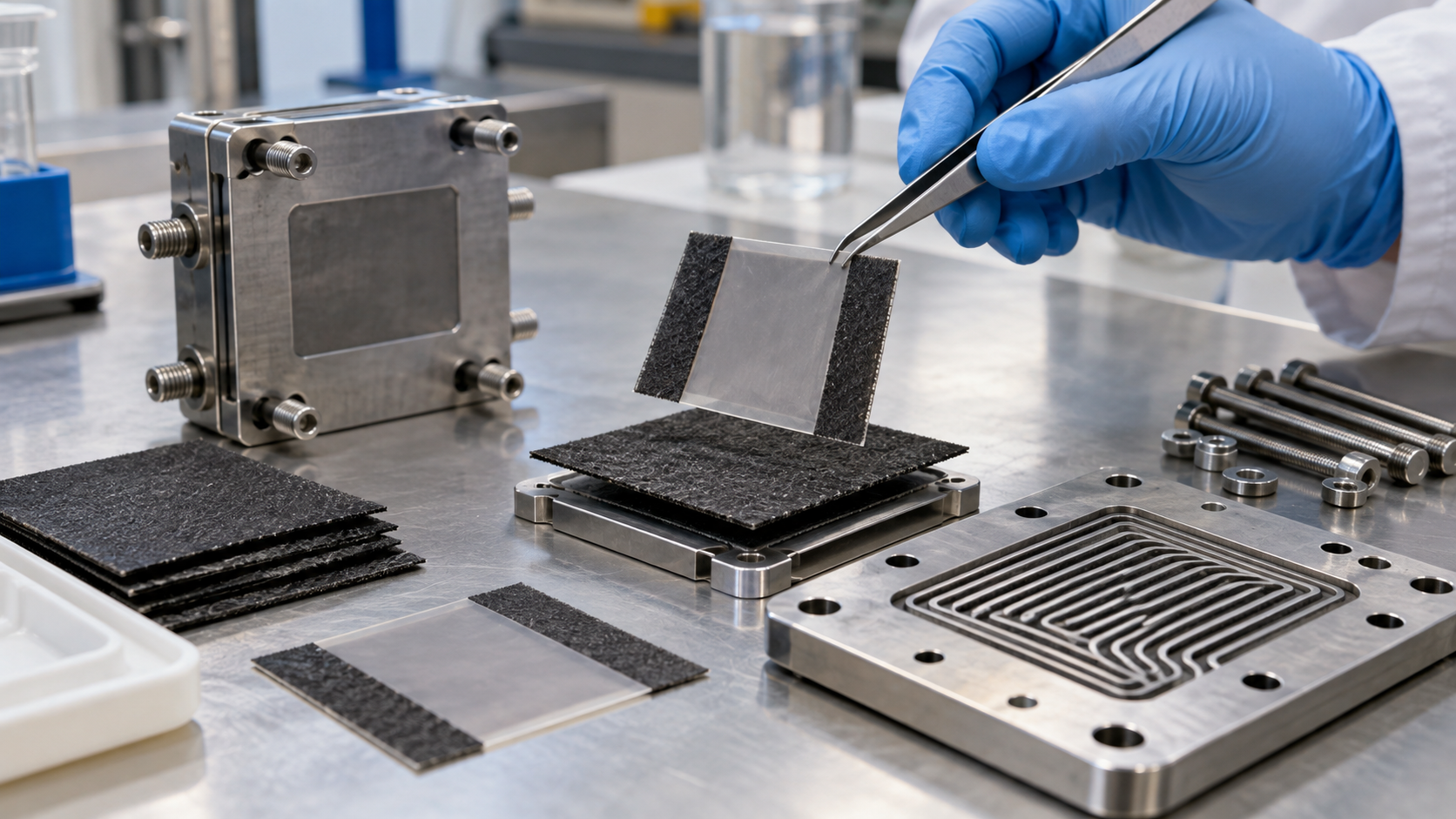
10. The link to fluoropolymers and PFAS
A PEFC uses fluorinated polymers in two places: the electrolyte membrane and the ionomer (PFSA and the like), and the PTFE in the diffusion layer (DOE's description). The status values in DOE's membrane targets are also for a fluorinated membrane (3M's PFIA type)Sourced.
As our explainer on fluoropolymers and PFAS lays out, the OECD (2021) definition of PFAS broadly covers substances with at least one fully fluorinated methyl or methylene carbon. PFSA side chains and backbones, and PTFE, contain such carbons, so they can fall within the definition (this article's commentary).
However, how PEFC membranes and ionomers are treated under regional PFAS rules (use exemptions, stage of proposals and so on) could not be confirmed in the official material this article consulted. The latest position has to be checked in official sources, case by case Not yet confirmed.
11. What is still hard, and what could not be confirmed
- Internal specifications of the current MIRAI, NEXO and CR-V e:FCEV: membrane thickness, platinum loading, cell area, rated-point voltage and current density could not be confirmed in published material
- Durability data from real driving: the comparison conditions and test methods behind the manufacturers' announced durability gains (up to twice and so on) are not public. DOE's durability value is a projection from a 2015 evaluation
- How PFAS rules treat PFSA: the position of regional rules on PEFC membranes and ionomers could not be confirmed
- PGM-free catalysts, hydrocarbon membranes, anion-exchange membranes: their adoption in production vehicles was not checked within the scope of this article
- Hydrogen purity and impurities (ISO 14687 and others): DOE says the platinum catalyst is sensitive to carbon monoxide (Sourced), but the link between vehicle hydrogen purity standards and degradation is not covered here
- Stacks for heavy-duty and commercial vehicles: the announcement of the 3rd-generation system was confirmed, but specification details could not be
- The status of the LANL slides: the cerium-immobilisation numbers are from presentation slides prepared for a meeting; they were not confirmed as peer-reviewed results
(1) How to read "manufacturer's stated value"
Range changes meaning with the test method (WLTP, EPA, Japan's WLTC), output with whether it is gross or net, and durability with test conditions. Numbers in one table are not necessarily on the same conditions.
(2) Material life depends on how the cell is operated
Catalyst dissolution, radical attack on the membrane and freeze damage all depend on the history of start/stop, potential, humidity and temperature. The life from a laboratory accelerated test is not the same thing as hours of real driving.
- A PEFC is hundreds of single cells in series, each a stack of membrane, catalyst layers, diffusion layers and plates. The MIRAI has 330 cells and a maximum output of 128 kW (manufacturer's stated value)Sourced
- When cell voltage falls from 0.8 V to 0.6 V, efficiency drops from 64% to 48% and waste heat rises from 0.56 to 1.08 times the electric outputOur calculation
- In DOE's 2020 record the 2017 MIRAI stack has about 0.3 g/kW of platinum-group metal against a target of 0.125 g/kW. For 90 kW, that is about 27 g against about 11 gOur calculation
- Degradation advances with start/stop, high potential, low humidity and sub-zero temperatures. The main modes are platinum dissolution and deposition in the membrane, carbon corrosion, and radical attack on the membraneSourced
- DOE's "status" is a patchwork of values, and no product has yet been shown to meet all targets at onceSourced
12. Glossary
- PEFC (polymer electrolyte fuel cell)
- A fuel cell with a polymer membrane as the electrolyte; also PEMFC. Operates at about 80 °C.
- MEA (membrane electrode assembly)
- The membrane, catalyst layers and gas diffusion layers stacked together: the power-producing core.
- PFSA
- Perfluorosulfonic acid. A fluorinated polymer with sulfonic-acid side chains, used for membranes and ionomers.
- Ionomer
- A polymer that conducts ions. Mixed into the catalyst layer as a path for protons.
- GDL (gas diffusion layer)
- The carbon-fibre paper outside the catalyst layer. It helps transport gases and remove water.
- Bipolar plate
- The plate that separates cells, connects them in series and carries gas and coolant channels.
- Crossover
- Leakage of hydrogen or oxygen through the membrane to the other side.
- OCV (open-circuit voltage)
- The voltage when no current is drawn. At high potential, membrane and catalyst degradation advances more easily.
- PGM (platinum group metals)
- Noble metals such as platinum. The amount in the catalyst is expressed in g/kW.
- Mass activity
- The oxygen-reduction current per milligram of platinum-group metal in the catalyst.
- Q/ΔT
- The stack's waste heat divided by the difference between coolant and ambient temperatures. Smaller means easier cooling.
- WLTP / WLTC / EPA
- Test methods for range and fuel economy. Conditions differ by region.
13. References
- Toyota Motor Corporation "MIRAI Main Specifications", March 2026 edition (PDF, in Japanese) — https://toyota.jp/pages/contents/mirai/002_p_001/pdf/mirai_spec_202603.pdf
- U.S. Department of Energy (DOE) Hydrogen and Fuel Cells Program Record 20005, "Automotive Fuel Cell Targets and Status", 31 August 2020 (PDF) — https://www.hydrogen.energy.gov/docs/hydrogenprogramlibraries/pdfs/20005-automotive-fuel-cell-targets-status.pdf
- U.S. Department of Energy (DOE) "DOE Technical Targets for Fuel Cell Systems and Stacks for Transportation Applications" — https://www.energy.gov/eere/fuelcells/doe-technical-targets-fuel-cell-systems-and-stacks-transportation-applications
- U.S. Department of Energy (DOE) "DOE Technical Targets for Polymer Electrolyte Membrane Fuel Cell Components" — https://www.energy.gov/eere/fuelcells/doe-technical-targets-polymer-electrolyte-membrane-fuel-cell-components
- U.S. Department of Energy (DOE) "Types of Fuel Cells" — https://www.energy.gov/eere/fuelcells/types-fuel-cells
- U.S. Department of Energy (DOE) "Parts of a Fuel Cell" — https://www.energy.gov/eere/fuelcells/parts-fuel-cell
- Toyota Motor Corporation "Toyota Develops New Fuel Cell System", news release, 14 February 2025 — https://global.toyota/en/newsroom/corporate/42218558.html
- Hyundai Motor Company "Hyundai Motor's All-New NEXO Sets New Standards in Hydrogen Technology and Electrified Mobility", 11 November 2025 — https://www.hyundai.com/worldwide/en/newsroom/detail/0000001056
- Hyundai Motor Company "Hyundai Motor Unveils 'the all-new NEXO' FCEV with Bold New Design and ...", 2 April 2025 — https://www.hyundai.com/worldwide/en/newsroom/detail/0000000927
- Honda "Honda Advances Hydrogen Strategy with Production Launch of Fuel Cell Electric Vehicle in Ohio", 6 June 2024 — https://global.honda/en/newsroom/news/2024/4240606eng.html
- Ettingshausen et al. "Dissolution and Migration of Platinum in PEMFCs Investigated for Start/Stop Cycling and High Potential Degradation", Fuel Cells, 11, 238-245, 2011 — https://doi.org/10.1002/fuce.201000051
- Agarwal, Komini Babu and Borup (LANL) "Cerium Immobilization Strategies", LA-UR-24-31241, 17 October 2024 (presentation slides for a meeting) — https://www.osti.gov/biblio/2472567
- Zaton, Rozière and Jones "Current understanding of chemical degradation mechanisms of perfluorosulfonic acid membranes and their mitigation strategies: a review", Sustainable Energy & Fuels, 1, 409-438, 2017 — https://doi.org/10.1039/c7se00038c
- Lin, Zhu et al. "Consistency analysis of polymer electrolyte membrane fuel cell stack during cold start", Applied Energy, 241, 2019 — https://doi.org/10.1016/j.apenergy.2019.03.091
- Kusoglu and Weber "New Insights into Perfluorinated Sulfonic-Acid Ionomers", Chemical Reviews, 117, 987-1104, 2017 — https://doi.org/10.1021/acs.chemrev.6b00159
14. Claim-to-source audit
| Claim in the text | Basis | Category |
|---|---|---|
| That the MIRAI's FC stack (model FCB130) is a polymer electrolyte type with a maximum output of 128 kW (174 PS) and 330 cells in series; three high-pressure tanks (64 + 52 + 25 = 141 L) at 70 MPa; fuel consumption of 146 and 152 km/kg (ministry examination value); and the specifications (March 2026 edition) | Toyota MIRAI main specificationsReference 1 https://toyota.jp/pages/contents/mirai/002_p_001/pdf/mirai_spec_202603.pdf | Sourced |
| The 2020 record: status and 2025 and ultimate targets for systems and stacks (efficiency 64, 65, 70%; power density 640, 650, 850 W/L; specific power 860, 650, 900 W/kg; cost 50, 40, 30 US$/kW; durability 4,130, 5,000, 8,000 hours; stack 3,100 W/L, 2,000 W/kg, Q/ΔT 2.4 kW/°C, US$22/kW and so on). The basis of each status value (Argonne assessment of the 2017 MIRAI, Hyundai 2012, model estimates, the 2015 fleet evaluation). The note that status values were not reached together. The MIRAI stack's PGM of about 0.3 g/kW. The Q/ΔT formula (reference voltage 1.25 V) and the 90 kW, 0.6 V, 80 °C example. Cold start (20 s at -20 °C; unassisted start at -30 °C) and the eight-hour soak | DOE Program Record 20005 (31 August 2020)Reference 2 https://www.hydrogen.energy.gov/docs/hydrogenprogramlibraries/pdfs/20005-automotive-fuel-cell-targets-status.pdf | Sourced |
| The 2015 status and 2020 and ultimate targets for systems and stacks, including start/stop durability (5,000 cycles), unassisted low-temperature start (-30 °C) and start-up energy | DOE technical targets for fuel cell systems and stacksReference 3 https://www.energy.gov/eere/fuelcells/doe-technical-targets-fuel-cell-systems-and-stacks-transportation-applications | Sourced |
| The 2015 status and 2020 targets for membranes, catalysts, MEAs and plates: proton resistance, crossover, mechanical and chemical durability and cost of the membrane (status based on a 3M PFIA-type membrane); PGM of 0.16 g/kW (target 0.125), mass activity, PGM-free catalyst at 0.016 A/cm² (target over 0.044); plate cost of US$7/kW (target 3), flexural strength, forming elongation, and the corrosion test environment (pH 3, 0.1 ppm HF, 80 °C) | DOE technical targets for PEM fuel cell componentsReference 4 https://www.energy.gov/eere/fuelcells/doe-technical-targets-polymer-electrolyte-membrane-fuel-cell-components | Sourced |
| That PEM fuel cells run at about 80 °C, start quickly and need a noble-metal catalyst, and are used mainly for transport | DOE, "Types of Fuel Cells"Reference 5 https://www.energy.gov/eere/fuelcells/types-fuel-cells | Sourced |
| How a fuel cell works (anode, cathode, electrolyte); the MEA (membrane, catalyst layers, diffusion layers); that the membrane for vehicles can be under 20 microns; platinum on carbon with ionomer; the diffusion layer as PTFE-coated carbon-fibre paper with a microporous layer; plates (metal, carbon, composite) and gaskets (rubbery polymer); and that a stack has hundreds of cells | DOE, "Parts of a Fuel Cell" and related pagesReference 6 https://www.energy.gov/eere/fuelcells/parts-fuel-cell | Sourced |
| The features of Toyota's 3rd-generation FC system (durability up to twice, fuel efficiency 1.2 times, 20% more range, large cost reduction); introduction after 2026 at the earliest; about 28,000 MIRAI in over 30 countries; more than 2,700 FC systems to more than 100 customers | Toyota news release (14 February 2025)Reference 7 https://global.toyota/en/newsroom/corporate/42218558.html | Sourced |
| The NEXO's stack maximum output of 110 kW (gross), net 94 kW (previous 95 and 85 kW), three tanks of 162.6 L, usable hydrogen up to 6.69 kg (previous 6.33 kg), range of 826 km (WLTP, 18-inch, European model), 0.81 and 0.89 kg/100 km, low-temperature operability, membrane structure, cell uniformity and the Wake Up anti-freezing function | Hyundai press releases (11 November 2025 and 2 April 2025)Reference 8 https://www.hyundai.com/worldwide/en/newsroom/detail/0000001056Reference 9 https://www.hyundai.com/worldwide/en/newsroom/detail/0000000927 | Sourced |
| The start of CR-V e:FCEV production (5 June 2024); the fuel cell system co-developed with GM, with durability doubled and cost cut by two-thirds against the previous Clarity Fuel Cell; EPA range of 270 miles; up to 29 miles of EV driving with plug-in charging; two hydrogen tanks | Honda news release (June 2024)Reference 10 https://global.honda/en/newsroom/news/2024/4240606eng.html | Sourced |
| Platinum dissolution and deposition in the membrane in start/stop and high-potential tests, and carbon corrosion (the main effect at high constant potential) | Ettingshausen et al. (Fuel Cells, 2011)Reference 11 https://doi.org/10.1002/fuce.201000051 | Sourced |
| That cerium depletion in cerium-doped membranes means failure; the immobilisation strategies (crown ethers, phosphonic acids); the accelerated test (OCV, 90 °C, 30% RH, 25 cm², about 30 microns) with fluoride emission down 24% and lifetime 1.8 times (310 and 550 hours); and the note of fluoride emission down 58% and lifetime 4 times for phosphonic acids | LANL slides LA-UR-24-31241 (2024)Reference 12 https://www.osti.gov/biblio/2472567 | Sourced |
| That the review arranges the mechanisms and mitigation of chemical degradation of PFSA membranes | Zaton et al. (Sustainable Energy & Fuels, 2017)Reference 13 https://doi.org/10.1039/c7se00038c | Sourced |
| That a stack under real-vehicle conditions started from -15 °C in 95 seconds, and the distribution of performance loss after a failed start | Lin et al. (Applied Energy, 2019)Reference 14 https://doi.org/10.1016/j.apenergy.2019.03.091 | Sourced |
| The complex behaviour of PFSA ionomers, the link between properties and structure, composite membranes, degradation and thin films | Kusoglu and Weber (Chemical Reviews, 2017)Reference 15 https://doi.org/10.1021/acs.chemrev.6b00159 | Sourced |
| Maximum output per cell (128 kW / 330 = about 388 W); the relation of cell voltage to efficiency and heat (64% and 0.56 times at 0.8 V; 48% and 1.08 times at 0.6 V); reproduction of DOE's example (about 2.4 kW/°C); the assumed calculation for the MIRAI (198 V, about 646 A, heat about 139 kW at 0.6 V); the amount of platinum-group metal (27 g, 14 g, 11 g, 2.4 times); the NEXO's 826 / 6.69 = 123.5 km/kg and 41.1 g/L; the MIRAI's 141 L x 40.2 g/L = about 5.7 kg; and the heat-rejection ratio (2.4 / 1.45 = 1.66) | Our calculation. Assumptions: DOE's formula (reference voltage 1.25 V), 90 kW gross, cell voltage of 0.6 V (the value DOE used for assessing the MIRAI, not the actual value for the current model), and DOE's density (40.2 g/L at 70 MPa and 15 °C). Idealised calculations, not values for real systems | Our calculation |
| Introduction of Toyota's 3rd-generation FC system (after 2026 at the earliest), and the treatment of PEFC membranes and ionomers under PFAS rules | Plans and unconfirmed items, not results; they are outlooksReference 7 https://global.toyota/en/newsroom/corporate/42218558.html | Not yet confirmed |
| Membrane thickness, platinum loading, cell area, rated-point voltage and current density of the current MIRAI, NEXO and CR-V e:FCEV; the basis of each maker's durability gains; the treatment of PEFCs under PFAS rules; the adoption of PGM-free catalysts, hydrocarbon membranes and anion-exchange membranes in vehicles; the link of hydrogen purity standards to degradation; and details of heavy-duty stacks | Could not be confirmed in primary sources within the scope of this article, so not described. This article's commentary | Commentary |
| The reading that membrane requirements conflict; that degradation depends on how the cell is operated (potential, humidity, temperature history); the explanation that product water can freeze and block pores below 0 °C; the reading that DOE's status is a patchwork and no product has been shown to meet all targets at once; that PFSA and PTFE can fall within the PFAS definition; and that waste heat becomes a thermal-design constraint | This article's summary and commentary based on published content. Not views stated by the institutions concerned | Commentary |
| That Figs. 1 to 4 are explanatory drawings rather than real cross-sections, micrographs or test records, and that Fig. 5 and the hero image are AI-generated images | Our note | Commentary |
Last updated 8 October 2026. Sources are limited to primary material (government and national laboratory records, official material from manufacturers, and peer-reviewed papers). Manufacturers' values are labelled as the manufacturer's stated values. Because the article includes structural readings and materials-design interpretations, those are marked as Commentary and kept separate from sourced fact. Membrane thickness, platinum loading and rated-point voltage of current vehicles, the basis of each maker's durability gains, the treatment of PEFCs under PFAS rules and real-world durability data are not stated here because no primary source could be confirmed. DOE's "status" is a patchwork of values from different sources, not a record of a product that met all targets at once. Hydrogen is a flammable gas and its handling is governed by law and standards. This article is an explanation, not advice on design, operation or handling. All figures are explanatory concept graphics. Figs. 1 to 4 are vector drawings; Fig. 5 and the hero image are AI-generated images, and none of them shows a real cross-section, micrograph or vehicle.