TECHNOLOGY EXPLAINER
High-Pressure Hydrogen Tanks
— a polymer liner inside a carbon-fibre shell holds hydrogen at 70 MPa
Fuel cell vehicles carry hydrogen compressed to a nominal working pressure of up to 70 MPa (700 bar). In DOE's April 2025 record (a 2023 projection), a system holding 5.6 kg of usable hydrogen weighs about 109 kg; hydrogen is about 5% of that, and about two-thirds (about 73 kg) is carbon-fibre composite. Hydrogen permeates the wall, rapid decompression damages the liner, and fire attacks the composite, so materials and tests are set out in detail in regulations and standards.
- What a high-pressure hydrogen tank is (the short version)
- 35 MPa and 70 MPa — what "nominal working pressure" means
- Types 1 to 5 — wall construction
- Our calculation: density of compressed hydrogen, and the mass and volume breakdown of a system
- A materials engineer's view (1): the wall is not set by hoop winding alone
- The liner and hydrogen permeation
- Rapid decompression and liner damage
- A materials engineer's view (2): hydrogen compatibility of metal parts (boss, valves, aluminium)
- Qualification tests — what is checked
- Fire and the pressure relief device (TPRD)
- Fatigue and service life — designing to leak before burst
- Standards and regulation
- What is still hard, and what could not be confirmed
- Glossary / References / Claim-to-source audit
Sourced = a statement in published material (link given)
Our calculation = a figure this article derived, with the assumptions spelled out
Not yet confirmed = a plan or target with no confirmed record of delivery
Structural readings and materials-design interpretations are marked separately as Commentary.
Hydrogen is a flammable gas, and high-pressure gas containers are subject to law and standards (in Japan, the High Pressure Gas Safety Act, among others). This article explains materials, principles, evaluation and regulation. It is not advice on the design, use or handling of any container.
1. What a high-pressure hydrogen tank is (the short version)
A high-pressure hydrogen tank is a vessel that squeezes hydrogen gas into a small volume at high pressure. Hydrogen is so light that, without high pressure, a car cannot carry enough of it.
- The current mainstream: DOE names compressed-gas tanks with nominal working pressures of 350 bar and 700 bar as the near-term technology for onboard storage, and calls physical storage the most mature hydrogen storage technologySourced
- Construction: the 700 bar Type IV that DOE uses for its projections consists of a polymer liner, metal bosses (end fittings), carbon-fibre composite, and polyurethane foam caps for impact protectionSourced
- What is hard: according to DOE, compressed-gas storage still falls short of targets mainly on hydrogen per unit weight, per unit volume, and on costSourced. Cost is dominated by the carbon-fibre compositeSourced
A high-pressure hydrogen tank splits "a shell that bears the pressure" and "a lining that keeps hydrogen in" into two different materials. The shell (carbon-fibre composite) takes the pressure; the lining (polymer liner) contains the hydrogen. The materials worries are hydrogen slowly seeping through the lining, the lining being damaged when pressure is released fast, and the shell being weak against heat.
2. 35 MPa and 70 MPa — what "nominal working pressure" means
Tank pressure is described by the nominal working pressure (NWP). UN GTR No. 13, the global technical regulation for hydrogen and fuel cell vehicles, defines NWP as the settled pressure of compressed gas in a fully fuelled container at a uniform temperature of 15 °CSourced. The maximum pressure during fuelling (maximum fuelling pressure) is 125% of NWPSourced.
The regulation covers systems with NWP up to 70 MPa. Phase 2 (2023) states that all new compressed hydrogen storage systems produced for on-road vehicle service shall have an NWP of 70 MPa or lessSourced.
| Item | NWP 35 MPa | NWP 70 MPa | Basis |
|---|---|---|---|
| Maximum fuelling pressure (125% of NWP) | 43.75 MPa | 87.5 MPa | Definition in GTR 13 [Ref. 1]. Values are Our calculation |
| Minimum burst pressure (200% of NWP) | 70 MPa | 140 MPa | GTR 13 Phase 2, 5.1.1.1 [Ref. 2]. Values are Our calculation |
| Same (225% of NWP) | 78.75 MPa | 157.5 MPa | The Phase 1 minimum. In Phase 2 a Contracting Party may apply 225% at its discretion for containers of 35 MPa or less [Refs. 1, 2]. Values are Our calculation |
The NWP definition, 125%, and 200%/225% are all Sourced (UN GTR No. 13 Phase 1 [Ref. 1], Amendment 1 [Ref. 2]). The pressure values in the table were converted from those percentages by this article.
3. Types 1 to 5 — wall construction
Pressure vessels are grouped into "types" by wall construction. ISO 11119 defines the types of composite-reinforced vessels as followsSourced.
- Type 2: a metal liner with composite (or steel wire) wound on the cylindrical part only. ISO 11119-1:2020 (November 2020, third edition) [Ref. 7]
- Type 3: a load-sharing metal liner with composite wound over the cylinder and domes. ISO 11119-2:2020 [Ref. 8]
- Type 4: a non-load-sharing metallic or non-metallic liner with composite wound over the whole vessel. ISO 11119-3:2020 [Ref. 9]
- Type 5: no liner, with a test pressure under 60 bar. ISO 11119-3:2020 [Ref. 9]
Each part of ISO 11119 covers vessels up to 450 l water capacity and a minimum design life of 15 years. The composite reinforcement is carbon, aramid or glass fibre, or a mixtureSourced. Japan's Container Safety Regulation defines a "hoop-wrapped container" as one wound with resin-impregnated continuous fibre by hoop winding (fibre wound roughly perpendicular to the axis) on the liner's cylindrical part only, and a "full-wrapped container" as one wound by helical or in-plane winding over the cylinder and the dome ("mirror") partsSourced.
Under the Regulation (Article 2), vehicle hydrogen containers are divided into seamless containers and fibre-reinforced plastic composite containers. Separately, composite containers that conform to the global technical regulation are defined as "international compressed hydrogen vehicle fuel system containers"Sourced.
4. Our calculation: density of compressed hydrogen, and the mass and volume breakdown of a system
(1) Hydrogen at 70 MPa is thinner than an ideal gas
DOE's April 2025 record (Record 24006) assumes a 700 bar Type IV tank with an interior volume of 144.2 L, 5.8 kg of stored hydrogen (5.6 kg usable) and a hydrogen temperature of 15 °CSourced. From these numbers we can check the density of hydrogen and its departure from an ideal gas.
- Actual density: 5.8 kg / 0.1442 m³ = about 40.2 kg/m³ (40.2 g/L). The record says NIST REFPROP was used for the interior volume
- As an ideal gas: ρ = PM/RT = (70 × 10&sup6; Pa × 2.01588 × 10−³ kg/mol) / (8.3145 J/(mol K) × 288.15 K) = about 58.9 kg/m³
- Compressibility factor Z: 58.9 / 40.2 = about 1.46. At 70 MPa the repulsion between hydrogen molecules matters, and the volume is about 46% larger (the density lower) than for an ideal gas
Assumptions and limits: the hydrogen temperature is 15 °C, and the stored mass and interior volume are DOE's design assumptions. No density for 35 MPa was calculated, because no primary-source value was checked for it.
(2) The breakdown of the system
The supplementary tables of the same record let us break down the system's mass and volume.
- Per unit mass: 5.6 kg usable hydrogen / 109 kg system = about 5.1 wt% (1.71 kWh/kg in DOE's energy terms). DOE's 2025 target is 0.055 (5.5 wt%, 1.8 kWh/kg)
- Per unit volume: 5.6 kg / 215.7 L = about 26 g/L (0.86 kWh/L). DOE's 2025 target is 0.040 kg/L (40 g/L, 1.3 kWh/L)
- Mass other than hydrogen: for 5.8 kg of hydrogen there are 72.7 kg of composite, 8.0 kg of liner, 0.9 kg of boss and 22 kg of other parts. Carrying 1 kg of hydrogen takes about 12.5 kg of composite alone (72.7 / 5.8)
- Conversion: the lower heating value of hydrogen was taken as 33.33 kWh/kg (1.71 kWh/kg = 5.6 × 33.33 / 109)
Limit: DOE's figures are a projection for high-volume production (100,000 units a year), not measurements of any real vehicle's tank. The record itself shows the distance from the 2025 targets: 1.71 kWh/kg against 1.8, 0.86 kWh/L against 1.3, and US$12.7/kWh against 9Sourced.
5. A materials engineer's view (1): the wall is not set by hoop winding alone
In a thin-walled cylinder, internal pressure makes the circumferential (hoop) stress twice the axial stress. Using that formula alone, it looks as if fibre need only be wound around the circumference.
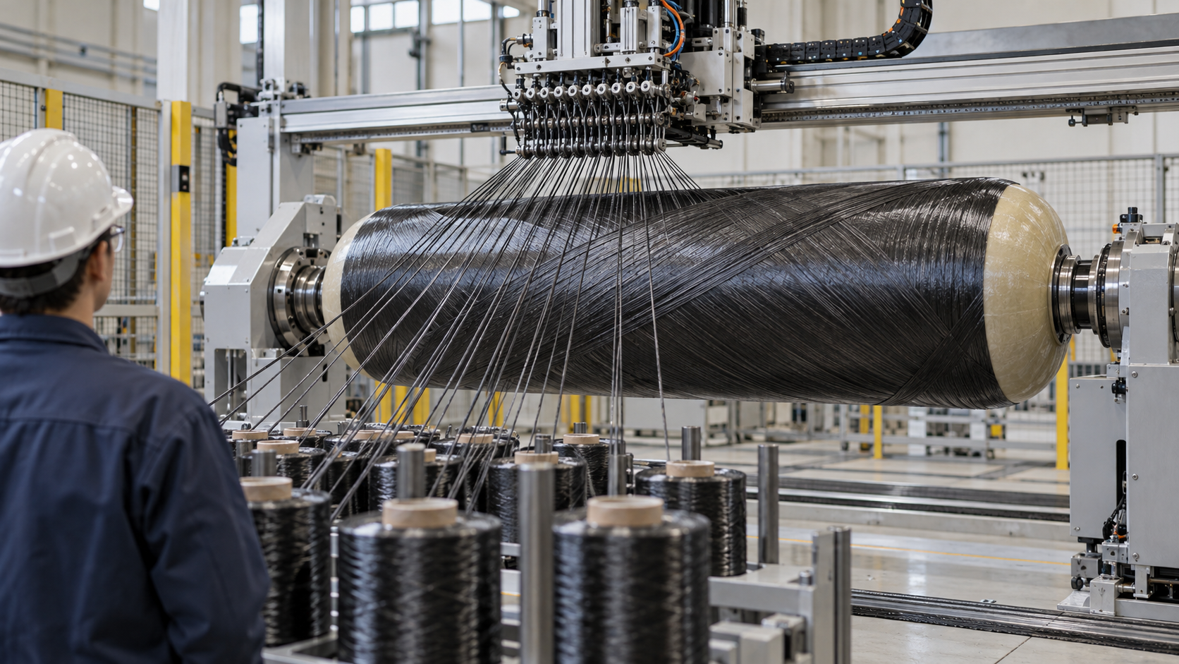
But a real tank has domes at both ends and axial loads. In DOE's model (147 L, 700 bar), of 106.6 kg of composite, 34.3 kg is hoop winding and 72.3 kg is helical windingSourced. Helical winding is about twice as heavy as hoop windingOur calculation (72.3 / 34.3 = 2.1).
- Assumptions: thin-walled cylinder. Burst pressure = 70 MPa × 2.25 = 157.5 MPa. Inner radius 19.8 cm, from the 39.6 cm inner diameter in DOE's 2025 record. Fibre tensile strength 5,123 MPa (the value the record adopts). Fibre carries all the circumferential load; resin and liner carry none
- Required fibre thickness: t = P × r / σ = 157.5 × 198 / 5,123 = about 6.1 mm
- Composite thickness: with the record's 51% fibre volume fraction, 6.1 / 0.51 = about 12 mm
This is a lower-bound estimate. Real designs are thicker once helical layers, the domes, the fraction of fibre strength that translates into load capacity (translation efficiency) and manufacturing scatter are included. DOE's record says these values are proprietary to the manufacturersSourced.
In the 2023 record the composite is 72.7 kg, lighter than 90.3 kg in 2019 (hoop-intensive winding). The fibre precursor changed from PAN-MA (a low-cost precursor) to PAN, fibre tensile strength from 4,900 MPa to 5,123 MPa, the resin from vinyl ester to epoxy, and the fibre volume fraction from 64.7% to 51%Sourced. Carbon fibre itself is covered in our explainer on CFRP and composite materials.
6. The liner and hydrogen permeation
The liner of a Type IV tank is the "lining" that keeps hydrogen in. The outer composite takes the pressure; the liner's job is to keep hydrogen from getting through. But polymers cannot stop hydrogen completely. How gases pass through a polymer (dissolving and diffusing) is covered in our explainer on barrier properties and coatings.
(1) The permeation the standard allows
UN GTR 13 sets the allowable leakage and permeation at 46 mL per hour or less per litre of water capacity of the storage system. The test fills the system with hydrogen, soaks it at 55-60 °C for at least 12 hours, and measures until the rate is steady (or for at most 500 hours)Sourced. The value is derived so that hydrogen concentration in a garage stays at or below 1% (a quarter of the 4% lower flammability limit). The regulation's explanation works through a vehicle with a total water capacity of 330 L or less in a 50 m³ garageSourced.
- Assumption: DOE's projected tank (144.2 L water capacity) permeates at exactly the limit, 46 mL/h/L
- 46 × 144.2 = 6,633 mL/h = about 6.6 L/h (about 110 mL per minute)
- For the 330 L total water capacity used in the GTR's example: 46 × 330 / 60 = 253 mL per minute (the same as the GTR's own calculation)
Caution: this applies the limit; it is not the permeation of a real tank. Actual permeation of a tank that meets the limit is normally expected to be far smaller, but this article did not confirm measured values.
(2) Liner material: from HDPE to polyamide
DOE's projection for 2019 takes a high-density polyethylene (HDPE) liner 0.5 cm thick; its 2023 projection takes polyamide (PA) 0.38 cm thickSourced. Beyond low permeation, liner materials are chosen for processability such as blow moulding, strength under cyclic pressure, and joining to the metal boss (this article's commentary).
Two published studies illustrate the materials work.
- Sun et al. evaluated polyamide 6 filled with lamellar inorganic components as a Type IV liner candidate. Hydrogen permeability measured at -10 to 85 °C and 25 to 50 MPa was 3 to 5 times lower than for polyamide 6, with tensile strength up 36%, bending strength up 17% and bending modulus up 12%. The study starts from the point that polymer liners are restricted commercially by their high hydrogen permeabilitySourced (the paper says the material meets the requirements of the hydrogen tank standard)
- Fujiwara et al. measured permeation through five polyethylenes with different free-volume fractions at up to 90 MPa of hydrogen. As pressure rose, the diffusion coefficient fell and the permeability coefficient fell with it. They explain this by free volume shrinking under hydrostatic pressureSourced
7. Rapid decompression and liner damage
Under high pressure, hydrogen dissolves into the liner. If the tank is emptied quickly, the hydrogen concentration left inside the liner sets up a pressure difference against the outside. The review by Jin et al. summarises that this rapid decompression can damage the liner, and says that understanding decompression damage is important for developing suitable liner materials and for commercialising Type IV tanksSourced.
Another damage mode is fatigue from cyclic pressure. Rondinella et al. studied an HDPE liner in a Type IV vessel for high-pressure storage that failed during a room-temperature pressure-cycling test. The failure appeared in the hemispherical head as cracks perpendicular to the liner's pinch-off line. They found no significant chemical or morphological change during manufacture (blow moulding, curing of the composite), and concluded that the most likely cause was fatigue related to the designSourced.
8. A materials engineer's view (2): hydrogen compatibility of metal parts (boss, valves, aluminium)
Even in a Type IV tank, metal parts such as the boss, shut-off valve and check valve are exposed to high-pressure hydrogen. In Types 1 and 3 the vessel body itself is metal. UN GTR 13 left material compatibility and hydrogen embrittlement to national regulations in Phase 1, and Phase 2 (2023) added requirements for fatigue testing in hydrogen and slow strain rate tensile (SSRT) testingSourced.
- Fatigue (notched specimens, option 1): at least three notched specimens with an elastic stress concentration factor of 3 or more, tested in hydrogen at 125% NWP, 293 ± 5 K, stress ratio 0.1 and 1 Hz or lower; each must exceed 105 cycles
- Fatigue (smooth specimens, option 2): smooth specimens at stress ratio -1 must exceed 2 × 10⁵ cycles. In addition, in SSRT in hydrogen at 228 ± 5 K, the yield strength must exceed 80% of that in air at the same temperature
- Test hydrogen: gas of at least 99.999% purity, with set limits on impurities
In other words, the standard uses fatigue in hydrogen and loss of ductility in tension in hydrogen as the pass/fail indicators for metal parts. This is the same kind of thinking as the evaluation of hydrogen pipelines (see our hydrogen pipeline explainer) (this article's commentary).
For aluminium alloys there is a separate test. GTR 13 says aluminium alloys have good resistance to hydrogen embrittlement and are candidate materials, but that some alloys suffer stress corrosion cracking in humid gas (HG-SCC). The cracking is driven by hydrogen atoms produced in the reaction of aluminium with water (2Al + 3H₂O → Al₂O₃ + 6H) collecting at the crack tip, and it can occur both outside and inside a vessel (water as an impurity in the hydrogen gas is the cause inside). Experts from Japan developed a test method for susceptibility to this cracking, which is included in an annex to the regulationSourced.
9. Qualification tests — what is checked
The container qualification tests of UN GTR 13 consist of tests that fix the "baseline" of new containers, "durability" tests that stack up degrading conditions in order, "on-road performance" tests with hydrogen gas, and a fire test.
What stands out is that the tests check not the strength of a new container but its strength after flaws, chemicals, heat and cycling. For example, a saw cut at least 0.75 mm deep and 200 mm long is made, pendulum impacts are applied, and sulphuric acid, sodium hydroxide, a gasoline-methanol mixture, a urea (ammonium nitrate) solution and windshield-washer fluid are held on the surface for at least 48 hours while the container is pressurised to 125% NWP or more. Pressure cycling to 80% and 125% NWP follows, then a burst, and the burst pressure must be at least 80% of the new-container median BP0Sourced.
According to the Phase 2 rationale, the burst pressure required after degradation is at least 80% of the new burst pressure and at least 180% NWP. Composites are materials whose strength can fall with flaws and chemicals, which is probably why the tests are ordered this way (this article's commentary).
10. Fire and the pressure relief device (TPRD)
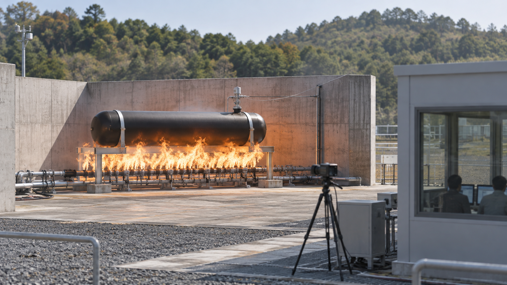
In a fire, the matrix resin of a carbon-fibre composite can soften or decompose and stop carrying pressure (this article's commentary). That is why containers carry a thermally activated pressure relief device (TPRD): a non-reclosing pressure relief device that opens on temperature and releases hydrogenSourced.
- How the test is conceived: the localized fire is applied at the point on the container farthest from the TPRD. The test assumes the worst case, in which the TPRD is not directly in the flameSourced (Phase 1 text)
- Pass criteria (Phase 2): the container must not rupture; it must vent continuously to below 1 MPa (within 1 hour for light-duty vehicles, within 2 hours for heavy-duty vehicles); and no jet flame over 0.5 m may arise except from the TPRD exhaust. If pressure has not fallen below 1 MPa in time, the system fails even without ruptureSourced
- Component tests for the TPRD: the regulation lists pressure cycling, accelerated life, temperature cycling, salt corrosion, vehicle environment, stress corrosion cracking, drop and vibration, leak, bench-top activation and flow testsSourced. The standard for the TPRD itself is ISO 19882:2025 (second edition, February 2025) [Ref. 11]
- Design changes: changing the TPRD hardware, its position or the vent lines requires the fire test to be repeatedSourced
11. Fatigue and service life — designing to leak before burst
A tank's pressure rises and falls with every fill. Repeated cycling fatigues the composite and the liner. GTR 13 guards against this with a "leak before burst" design philosophy.
| Item | Requirement | Source |
|---|---|---|
| Baseline pressure cycle test | Three new containers are hydraulically cycled to 125% NWP for up to 22,000 cycles or until a leak occurs. A leak must not occur before 7,500 or 11,000 cycles for light-duty vehicles (at the Contracting Party's discretion), or before 11,000 cycles for heavy-duty vehicles (Phase 2) | [Ref. 2] |
| Phase 1 cycle counts | The number of cycles before which no leak may occur, for a 15-year service life, is set by each Contracting Party at 5,500, 7,500 or 11,000 | [Ref. 1] |
| Service life | Phase 1 covers 15 years or less; Phase 2 covers 25 years or less. For a life over 15 and up to 25 years, the no-leak cycle count is 11,000 | [Refs. 1, 2] |
| DOE target | Operational cycle life (1/4 tank to full) of 1,500 cycles (for 2020, 2025 and ultimate) | [Ref. 5] |
All Sourced (UN GTR 13 Phase 1 [Ref. 1], Amendment 1 [Ref. 2], DOE [Ref. 5]).
- 2 per day × 365 days × 15 years = 10,950 cycles (the GTR explains its upper limit of 11,000 as a vehicle in high-usage service with 2 full fuellings a day for 15 years)
- 1 per day × 365 days × 15 years = 5,475 cycles (close to the lower figure of 5,500)
- 22,000 cycles × 350 km per fill = about 7.7 million km (the GTR says "well over 7 million" at 350-500 km per fill)
Limit: 350 km per fill is this article's choice from the low end of the range the GTR gives (350-500 km, and 320-480 km elsewhere). Real usage, such as taxis and commercial vehicles, differs by jurisdiction.
On why it stresses leaking first, the regulation says that a leak (which leads to the vehicle being stopped and repaired) should come before a rupture, which is the more severe event. Because rupture is more severe, its probability per cycle should be lower, so confirming that there is no rupture takes more cycles (22,000) than confirming that there is no leak (7,500 to 11,000)Sourced.
12. Standards and regulation
Vehicle hydrogen containers are governed by the overlap of a UN global technical regulation, ISO standards and national law. Here is what published documents confirm.
| Standard / instrument | Content | Stage (date) |
|---|---|---|
| UN GTR No. 13 Phase 1 | Global technical regulation on hydrogen and fuel cell vehicles. Sets qualification tests for compressed hydrogen storage systems (burst at 225% NWP or more, 22,000 cycles, fire test and others) | Established in the Global Registry 27 June 2013 (document dated 19 July 2013) |
| UN GTR No. 13 Amendment 1 (Phase 2) | Minimum burst pressure lowered to 200% NWP (225% at a Contracting Party's discretion for 35 MPa or less); heavy-duty vehicles added; service life up to 25 years; hydrogen material-compatibility tests (fatigue, SSRT) and the HG-SCC test for aluminium alloys added | Established in the Global Registry 21 June 2023 (document dated 17 July 2023) |
| ISO 11119-1, -2, -3:2020 | Design, construction and testing of composite gas cylinders. Part 1 covers Type 2, Part 2 Type 3, Part 3 Types 4 and 5. All cover up to 450 l and a minimum design life of 15 years | Published November 2020 |
| ISO 19881:2025 | "Gaseous hydrogen — Land vehicle fuel containers". Performance-based requirements for compressed hydrogen vehicle containers; stated to align with UN GTR 13 | Second edition, published June 2025 (the 2018 edition was replaced) |
| ISO 19882:2025 | "Gaseous hydrogen — Thermally activated pressure relief devices for compressed hydrogen vehicle fuel containers" | Second edition, published February 2025 (the 2018 edition was replaced) |
| Container Safety Regulation (Ministry of International Trade and Industry Order No. 50 of 1966, Japan) | A container regulation under the High Pressure Gas Safety Act. Article 2 defines "compressed hydrogen vehicle fuel system containers" and separately defines composite containers conforming to the global technical regulation as "international compressed hydrogen vehicle fuel system containers" | Enacted 25 May 1966 Current version in force from 12 June 2026 (as shown by e-Gov) |
| Related national and regional rules (as listed by GTR 13) | The EU General Safety Regulation (EU) 2019/2144 (hydrogen safety refers to UN Regulation No. 134); in Japan, Attachment 100 to the detailed safety standards notification (technical standard for compressed hydrogen fuel systems). Examples of standards: CSA/ANSI HGV 2:21 (vehicle containers) and SAE J2601 (fuelling protocol) | Listed by GTR 13; the revision status of each was not checked in this article |
All Sourced (UN GTR 13 [Refs. 1, 2], ISO [Refs. 7-11], e-Gov Law Search [Ref. 12]). Some standard texts are paid, so this article stays with titles, scope and public portions.
In Japan, vehicle compressed-hydrogen containers fall under the Container Safety Regulation of the High Pressure Gas Safety Act. This article has not checked the specific requirements for manufacture, inspection or use.
13. What is still hard, and what could not be confirmed
- Figures for 35 MPa tanks: hydrogen density, and the mass, volume and cost of the system, are not given because values on matched conditions could not be confirmed in primary sources
- Specifications and structure of tanks in production vehicles: the layers, hydrogen capacity and mass of tanks from Toyota, Honda, Hyundai and others are not covered here (see the explainer on fuel cell vehicles)
- Measured hydrogen permeability of liners: the GTR limit was confirmed, but representative permeability values for HDPE, polyamide and so on, by temperature and pressure on matched conditions, could not be
- Temperature rise during fuelling and pre-cooling: the heating during fast fuelling and the details of SAE J2601 were not confirmed within the scope of this article
- Heavy-duty vehicles, ships and rail, Type 5 and conformable tanks: not covered here
- Details of the standards' texts: the test conditions and pass criteria in ISO 11119, ISO 19881 and ISO 19882 are paid and were not checked
- The liner values in DOE's record: the supplementary table of the 2023 projection gives the liner as 8.0 kg and 8.4 L (a ratio of about 0.95 kg/L). Whether that can be taken as the value for polyamide was not confirmed
(1) A projection is not a real tank
DOE's records are design projections for 100,000 units a year, assuming a single tank with 5.6 kg of usable hydrogen. They differ from vehicles that carry several tanks and from low-volume tanks.
(2) Targets and current status are different quantities
Against DOE's 2025 targets (5.5 wt%, 1.8 kWh/kg, 40 g/L, US$9/kWh), the 2023 projection is 1.71 kWh/kg, 0.86 kWh/L (about 26 g/L) and US$12.7/kWh. Per unit mass it has come close to the target, but per unit volume it is about two-thirds of the targetOur calculation (26 / 40).
(3) The regulations keep changing
GTR 13 was amended in 2023, and its next phase (Phase 3) is expected to discuss requirements on material compatibility and hydrogen embrittlement Not yet confirmed. ISO 11119-2 is under revision (ISO/AWI 11119-2).
- Nominal working pressure (NWP) is the pressure at 15 °C; the maximum fuelling pressure is 125% of it, and the minimum burst pressure is 200% (Phase 2; 225% may be chosen for 35 MPa or less)Sourced
- The compressibility factor of hydrogen at 70 MPa and 15 °C is about 1.46, so its volume is about 46% larger than an ideal gas, as DOE's values implyOur calculation
- A 700 bar Type IV system weighs about 109 kg, about two-thirds composite and about 5% hydrogen (DOE's 2023 projection)Sourced
- Helical winding is heavier than hoop winding (about twice as heavy in DOE's 2015 model)Sourced
- The permeation limit is 46 mL per hour per litre of water capacity; the fire test requires no rupture and venting to below 1 MPa; and the life design is "leak before burst"Sourced
- Phase 2 added hydrogen fatigue and SSRT tests for metal partsSourced
14. Glossary
- NWP (nominal working pressure)
- The pressure of a fully fuelled container's hydrogen once settled at 15 °C.
- Maximum fuelling pressure
- The highest pressure applied during fuelling. 125% of NWP.
- Compressibility factor Z
- How many times larger a real gas's volume is than an ideal gas's. Above 1 for hydrogen at high pressure.
- Liner
- The lining on the inside of a vessel that keeps the gas in. Polymer or metal.
- Boss
- The metal fitting at the end of a vessel, to which valves and relief devices are attached.
- Hoop winding
- Winding fibre roughly perpendicular to the cylinder axis (circumferentially).
- Helical winding
- Winding fibre helically over the cylinder and domes. It carries axial and dome loads.
- TPRD
- Thermally activated pressure relief device. It releases hydrogen in a fire and does not reclose.
- Burst pressure (BP0)
- The median pressure at which new containers burst when hydraulically pressurised.
- SSRT
- Slow strain rate tensile test, used to assess hydrogen embrittlement.
- HG-SCC
- Stress corrosion cracking of aluminium alloys in humid gas. It can occur with water in the hydrogen gas as well.
- Global technical regulation (GTR)
- A UN regulation for harmonising vehicle safety and other requirements worldwide.
- ISO 11119
- The standard for the design, construction and testing of composite gas cylinders. It covers Types 2 to 5.
- Lower heating value
- Heat of combustion excluding the condensation heat of the water vapour formed. For hydrogen, 33.33 kWh/kg.
15. References
- UNECE Global technical regulation No. 13: Global technical regulation on hydrogen and fuel cell vehicles (ECE/TRANS/180/Add.13), established in the Global Registry 27 June 2013 (PDF) — https://documents.un.org/api/symbol/access?s=ECE/TRANS/180/Add.13&l=en&t=pdf
- UNECE UN Global Technical Regulation No. 13 Hydrogen and Fuel Cell Vehicles, Amendment 1 (ECE/TRANS/180/Add.13/Amend.1), established in the Global Registry 21 June 2023 (PDF) — https://documents.un.org/api/symbol/access?s=ECE/TRANS/180/Add.13/Amend.1&l=en&t=pdf
- U.S. Department of Energy (DOE) Hydrogen Program Record 24006, "Onboard Type IV Compressed Hydrogen Storage System - Cost and Performance Status", 28 April 2025 (PDF) — https://www.hydrogen.energy.gov/docs/hydrogenprogramlibraries/pdfs/24006-onboard-storage-cost-performance-status.pdf
- U.S. Department of Energy (DOE) Hydrogen and Fuel Cells Program Record 15013, "Onboard Type IV Compressed Hydrogen Storage System - Cost and Performance Status 2015" (PDF) — https://www.hydrogen.energy.gov/pdfs/15013_onboard_storage_performance_cost.pdf
- U.S. Department of Energy (DOE) "DOE Technical Targets for Onboard Hydrogen Storage for Light-Duty Vehicles" — https://www.energy.gov/eere/fuelcells/doe-technical-targets-onboard-hydrogen-storage-light-duty-vehicles
- U.S. Department of Energy (DOE) "Physical Hydrogen Storage" — https://www.energy.gov/eere/fuelcells/physical-hydrogen-storage
- ISO ISO 11119-1:2020 Gas cylinders - Design, construction and testing of refillable composite gas cylinders and tubes - Part 1: Hoop wrapped fibre reinforced composite gas cylinders and tubes up to 450 l — https://www.iso.org/standard/75815.html
- ISO ISO 11119-2:2020 Gas cylinders - Design, construction and testing of refillable composite gas cylinders and tubes - Part 2: Fully wrapped fibre reinforced composite gas cylinders and tubes up to 450 l with load-sharing metal liners — https://www.iso.org/standard/75816.html
- ISO ISO 11119-3:2020 Gas cylinders - Design, construction and testing of refillable composite gas cylinders and tubes - Part 3: Fully wrapped fibre reinforced composite gas cylinders and tubes up to 450 l with non-load-sharing metallic or non-metallic liners or without liners — https://www.iso.org/standard/75817.html
- ISO ISO 19881:2025 Gaseous hydrogen - Land vehicle fuel containers — https://www.iso.org/standard/19881
- ISO ISO 19882:2025 Gaseous hydrogen - Thermally activated pressure relief devices for compressed hydrogen vehicle fuel containers — https://www.iso.org/standard/82596.html
- e-Gov Law Search Container Safety Regulation (Order of the Minister of International Trade and Industry No. 50 of 1966), Japanese text (in Japanese) — https://laws.e-gov.go.jp/law/341M50000400050
- Jin et al. "Review of Decompression Damage of the Polymer Liner of the Type IV Hydrogen Storage Tank", Polymers, 15, 2258, 2023 — https://doi.org/10.3390/polym15102258
- Rondinella et al. "Study of the Failure Mechanism of a High-Density Polyethylene Liner in a Type IV High-Pressure Storage Tank", Polymers, 16, 779, 2024 — https://doi.org/10.3390/polym16060779
- Sun et al. "Research on hydrogen permeability of polyamide 6 as the liner material for type IV hydrogen storage tank", International Journal of Hydrogen Energy, 45, 24980-24990, 2020 — https://doi.org/10.1016/j.ijhydene.2020.06.174
- Fujiwara et al. "Hydrogen permeation under high pressure conditions and the destruction of exposed polyethylene", International Journal of Hydrogen Energy, 46, 11832-11848, 2021 — https://doi.org/10.1016/j.ijhydene.2020.12.223
- NIST Chemistry WebBook, "Hydrogen" (molecular weight) — https://webbook.nist.gov/cgi/cbook.cgi?ID=C1333740
- NIST Fundamental Physical Constants, molar gas constant — https://physics.nist.gov/cgi-bin/cuu/Value?r
16. Claim-to-source audit
| Claim in the text | Basis | Category |
|---|---|---|
| Definition of nominal working pressure (settled pressure at 15 °C); maximum fuelling pressure at 125% of NWP; the Phase 1 minimum burst pressure (225% NWP, over 350% for glass-fibre); the baseline cycle life (22,000 cycles at 125% NWP, no leak before 5,500, 7,500 or 11,000); the permeation limit (46 mL/h per litre of water capacity) and its rationale (50 m³ garage, 330 L, 253 mL/min); service life of 15 years or less; the TPRD definition; applying the localized fire farthest from the TPRD and the fire-test temperature table; re-testing when the TPRD changes; and the deferral of material compatibility and embrittlement to national rules in Phase 1 | UN GTR No. 13 (ECE/TRANS/180/Add.13, 2013)Reference 1 https://documents.un.org/api/symbol/access?s=ECE/TRANS/180/Add.13&l=en&t=pdf | Sourced |
| Phase 2 (Amendment 1): minimum burst pressure 200% NWP (225% at a Contracting Party's discretion for 35 MPa or less); 7,500 or 11,000 cycles for light-duty, 11,000 for heavy-duty, 11,000 for a 15-25 year life; service life of 25 years or less; NWP of 70 MPa or less; residual burst at least 80% of BP0 and at least 180% NWP at end of life; the flaw (0.75 mm deep, 200 mm long), five chemicals, 48 hours and 125% NWP or more; high-temperature hold (125% NWP, 85 °C, 1,000 hours or more); 500 hydrogen cycles and the permeation test (55-60 °C, up to 500 hours); fire-test pass criteria (vent below 1 MPa, 1 hour light-duty, 2 hours heavy-duty, no jet flame over 0.5 m, no rupture); the list of TPRD component tests; the fatigue and SSRT tests in hydrogen (notched and smooth, 125% NWP, 293 K and 228 K, 105 and 2 × 10⁵ cycles, 80% yield strength); HG-SCC of aluminium alloys; the Phase 3 agenda; the rationale for cycle counts (2 per day for 15 years, distance, leak before burst); and the two-layer description of liner and outer layer | UN GTR No. 13 Amendment 1 (2023)Reference 2 https://documents.un.org/api/symbol/access?s=ECE/TRANS/180/Add.13/Amend.1&l=en&t=pdf | Sourced |
| The projection for a 700 bar Type IV system: interior volume 144.2 L, 5.8 kg stored (5.6 kg usable), 15 °C, design safety factor 2.25, inner diameter 39.6 cm, liner from HDPE to PA and from 0.5 cm to 0.38 cm, changes in fibre precursor, tensile strength, resin and volume fraction, composite mass (90.3 kg in 2019, 72.7 kg in 2023), the mass and volume breakdown, polyurethane foam caps, 1.71 kWh/kg, 0.86 kWh/L, US$12.7/kWh (2020 dollars, 100,000 units a year), and the comparison with the 2025 targets | DOE Program Record 24006 (28 April 2025)Reference 3 https://www.hydrogen.energy.gov/docs/hydrogenprogramlibraries/pdfs/24006-onboard-storage-cost-performance-status.pdf | Sourced |
| The model calculation for a 147 L, 700 bar Type IV tank (5.9 kg stored): composite mass (91.0 kg in 2013, 106.6 kg in 2015, 99.6 kg and 97.0 kg with low-cost resin) and the hoop/helical split, the layer counts (46 hoop, 32 helical) and thicknesses (15.64 mm, 21.76 mm), the safety factor of 2.25 (burst at 1,575 bar or more), and calibration against burst tests of 35 L tanks | DOE Program Record 15013 (2015)Reference 4 https://www.hydrogen.energy.gov/pdfs/15013_onboard_storage_performance_cost.pdf | Sourced |
| DOE technical targets (2020, 2025, ultimate: per mass, per volume, cost, operational cycle life of 1,500 and others) | DOE technical targets pageReference 5 https://www.energy.gov/eere/fuelcells/doe-technical-targets-onboard-hydrogen-storage-light-duty-vehicles | Sourced |
| That onboard physical storage is 350 bar and 700 bar compressed-gas tanks; that physical storage is the most mature technology and needs improvement in hydrogen per mass and volume and in cost; and that cost is dominated by the carbon-fibre composite | DOE, "Physical Hydrogen Storage"Reference 6 https://www.energy.gov/eere/fuelcells/physical-hydrogen-storage | Sourced |
| The definition of Type 2 (metal liner, composite or steel wire on the cylinder only), up to 450 l, minimum design life of 15 years, published November 2020 (third edition) | ISO 11119-1:2020Reference 7 https://www.iso.org/standard/75815.html | Sourced |
| The definition of Type 3 (load-sharing metal liner, full wrap) and that a new edition is under development (ISO/AWI 11119-2) | ISO 11119-2:2020Reference 8 https://www.iso.org/standard/75816.html | Sourced |
| The definitions of Type 4 (non-load-sharing liner, full wrap) and Type 5 (no liner, test pressure under 60 bar); up to 450 l; minimum design life of 15 years; carbon, aramid and glass fibre; published November 2020 | ISO 11119-3:2020Reference 9 https://www.iso.org/standard/75817.html | Sourced |
| That ISO 19881:2025 is the second edition (June 2025), sets performance-based requirements for compressed hydrogen containers and states alignment with UN GTR 13 | ISO 19881:2025Reference 10 https://www.iso.org/standard/19881 | Sourced |
| That ISO 19882:2025 is the second edition (February 2025), and its title | ISO 19882:2025Reference 11 https://www.iso.org/standard/82596.html | Sourced |
| Article 2 of the Container Safety Regulation (No. 50 of 1966): definitions of hoop-wrapped container, full-wrapped container, compressed hydrogen vehicle fuel system container and international compressed hydrogen vehicle fuel system container (composite containers conforming to the global technical regulation); the enactment date (25 May 1966) and the date the current version took effect (12 June 2026) | e-Gov Law SearchReference 12 https://laws.e-gov.go.jp/law/341M50000400050 | Sourced |
| That hydrogen dissolves into the liner under high pressure and that rapid decompression can damage the liner through the pressure difference caused by internal hydrogen concentration; and that understanding decompression damage matters for liner materials and commercialising Type IV tanks | Jin et al. (Polymers, 2023)Reference 13 https://doi.org/10.3390/polym15102258 | Sourced |
| That an HDPE liner of a Type IV vessel for high-pressure storage failed in a room-temperature cycling test, the cracks in the hemispherical head, no significant change in manufacture, and design-related fatigue as the most likely cause | Rondinella et al. (Polymers, 2024)Reference 14 https://doi.org/10.3390/polym16060779 | Sourced |
| The evaluation of polyamide 6 filled with lamellar inorganic components at -10, 25 and 85 °C and 25, 35 and 50 MPa: permeability 3 to 5 times lower, tensile strength up 36%, bending strength up 17%, bending modulus up 12%, and the starting point that polymer liners are restricted by high permeability | Sun et al. (IJHE, 2020)Reference 15 https://doi.org/10.1016/j.ijhydene.2020.06.174 | Sourced |
| That five polyethylenes were evaluated at up to 90 MPa of hydrogen, and that the diffusion and permeability coefficients fell as pressure rose, explained by shrinking free volume | Fujiwara et al. (IJHE, 2021)Reference 16 https://doi.org/10.1016/j.ijhydene.2020.12.223 | Sourced |
| The molar mass of hydrogen (2.01588 g/mol) and the gas constant (8.3145 J/(mol K)), used for the ideal-gas density | NISTReference 17 https://webbook.nist.gov/cgi/cbook.cgi?ID=C1333740Reference 18 https://physics.nist.gov/cgi-bin/cuu/Value?r | Sourced |
| Hydrogen density at 70 MPa and 15 °C of about 40.2 kg/m³ (5.8 kg / 0.1442 m³) against about 58.9 kg/m³ for an ideal gas, and a compressibility factor of about 1.46; the converted values of NWP, maximum fuelling pressure and burst pressure (43.75, 87.5, 70, 140, 78.75, 157.5 MPa); the mass and volume shares (hydrogen 5%, composite 67%, liner 7%, boss 1%, other parts 20%; by volume 67% for the vessel interior and so on); about 5.1 wt% and about 26 g/L; about 12.5 kg of composite per kg of hydrogen; helical winding about 2.1 times the mass of hoop winding; the lower-bound fibre thickness from hoop loading (about 6.1 mm, about 12 mm of composite); applying the GTR permeation limit (about 6.6 L/h for 144.2 L, 253 mL/min for 330 L); the cycle-count conversions (10,950, 5,475, about 7.7 million km); and the ratio to the target (26 / 40) | Our calculation. Assumptions: ideal gas and 15 °C, DOE's design assumptions (interior volume, masses, inner diameter, fibre strength and volume fraction), the thin-wall formula, and a lower heating value of hydrogen of 33.33 kWh/kg. DOE's projections are not measurements of real tanks, and the hoop-only formula is a lower bound, not a design value | Our calculation |
| The distance of DOE's 2025 targets from the projection, and that GTR 13 Phase 3 is expected to take up material compatibility and hydrogen embrittlement | Plans or discussions in progress, not results; they are outlooksReference 2 https://documents.un.org/api/symbol/access?s=ECE/TRANS/180/Add.13/Amend.1&l=en&t=pdfReference 5 https://www.energy.gov/eere/fuelcells/doe-technical-targets-onboard-hydrogen-storage-light-duty-vehicles | Not yet confirmed |
| Figures for 35 MPa tanks, the structure and specifications of tanks in production vehicles (Toyota, Honda, Hyundai and others), representative measured hydrogen permeability, the temperature rise during fuelling and the details of SAE J2601, heavy-duty, ship and rail use, Type 5 and conformable tanks, the test conditions in the ISO standards, and how to treat the liner mass-to-volume ratio in the DOE record (about 0.95 kg/L) | Could not be confirmed in primary sources within the scope of this article, so not described. This article's commentary | Commentary |
| The reading from helical winding being heavier that hoop stress alone does not set the wall weight; that liner materials are chosen on more than low permeability (processability, fatigue, joining to the boss); that metal parts pass or fail on fatigue in hydrogen and loss of ductility; the reading that the test order reflects composites losing strength to flaws and chemicals; and the explanation that the matrix resin of a carbon-fibre composite can soften or decompose in fire and stop carrying pressure | This article's summary and commentary based on published content. Not views stated by the institutions concerned | Commentary |
| That Figs. 1 to 6 are explanatory drawings rather than real observations, design drawings or test records, and that Fig. 7 and the hero image are AI-generated images | Our note | Commentary |
Last updated 6 October 2026. Sources are limited to primary material (UN regulations, standards bodies, government and national laboratory records, law and peer-reviewed papers). Because the article includes structural readings and materials-design interpretations, those are marked as Commentary and kept separate from sourced fact. Figures for 35 MPa tanks, specifications of production-vehicle tanks, representative measured hydrogen permeability, temperature rise during fuelling and the test conditions in the standards' texts are not stated here because no primary source could be confirmed. DOE's figures are design projections for high-volume production, not measurements of real tanks. Hydrogen is a flammable gas and handling of containers is governed by law and standards. This article is an explanation, not advice on design, use or handling. All figures are explanatory concept graphics. Figs. 1 to 6 are vector drawings; Fig. 7 and the hero image are AI-generated images, and none of them shows a real cross-section, micrograph or physical facility.