TECHNOLOGY EXPLAINER
Supercapacitors
— what does storing energy by lining up ions on a surface do well, and what can it not do?
A supercapacitor (electric double-layer capacitor) does not store energy through a chemical reaction as a battery does; it lines up ions at the boundary between electrode and electrolyte. That makes it strong in power and lifetime, but its energy density is smaller than a battery's by orders of magnitude. This article covers the double-layer principle, electrode materials (activated carbon, graphene, CNTs, MXene), pseudocapacitance, electrolytes and voltage, how to read a Ragone plot, and applications and limits, drawing on peer-reviewed papers, manufacturers' datasheets and the official pages of international standards, from a materials engineer's point of view. It is not design, purchasing or safety advice.
- What a supercapacitor is, in three points
- The electric double layer: aligned ions, not a reaction
- Our calculation: reproducing datasheet numbers from formulas
- A materials engineer's view (1): capacitance is set by the pores ions can enter, not by surface area
- Electrode material families: activated carbon, graphene, CNTs, MXene, oxides
- A materials engineer's view (2): pitfalls in reading “F/g” in papers
- Electrolytes and voltage: energy scales with the square of voltage
- Energy density and power density: reading a Ragone plot with its conditions
- Applications and limits
- Strengths, weaknesses and open issues
- Glossary / References / Claim-to-source audit
Sourced = stated in published material (link given)
Our calculation = a value this article derived from assumptions it states
Not yet confirmed = a plan or target with no confirmed track record
Structural readings and materials-design interpretations are marked separately as Commentary. An Inference is shown in bold.
Manufacturers' figures are manufacturer's stated values, given with their test conditions and edition. Paper values are as stated in the abstracts; because conditions differ from paper to paper, they are not ranked against each other.
1. What a supercapacitor is, in three points
A supercapacitor (also called an ultracapacitor or electrochemical capacitor) is an energy-storage device that sits between a battery and a capacitor.
- Two ways of storing charge: a review sorts supercapacitors into those that store charge by ion adsorption (electrochemical double-layer capacitors) and those that use fast surface redox reactions (pseudocapacitors) Sourced [Reference 1].
- Strengths: Nippon Chemi-Con explains that, because the device uses no chemical reaction and stores energy solely by the physical movement of ions to the surface of activated carbon, it degrades little and withstands multimillion charge-discharge cycles Sourced (the manufacturer's explanation) [Reference 17]. The Skeleton Technologies datasheet lists an equivalent series resistance (ESR) of 0.12 mΩ and a cycle life of 1,000,000 cycles (with conditions) [Reference 15].
- Limit: the specific energy in the same datasheet is 8.27 Wh/kg. That is about one-fortieth to one-fiftieth of the lithium-ion cell datasheets (Amprius, 340–400 Wh/kg [Reference 21]) Our calculation (a rough figure from values with different conditions, not a ranking; Section 8).
A supercapacitor is not a “small battery”: it is a storage device that can move very large currents in and out, and whose contents shrink with the square of the voltage. The stored energy is proportional to voltage squared, and the voltage falls as it discharges. Both its strengths and its limits follow from that one property.
2. The electric double layer: aligned ions, not a reaction
An ordinary capacitor stores charge with a dielectric between two electrodes. An electric double-layer capacitor (EDLC) puts the charge instead at the boundary between electrode and electrolyte. Nippon Chemi-Con calls this boundary the “electric double layer” and explains that applying a voltage aligns ions on the electrode surface Sourced [Reference 17].
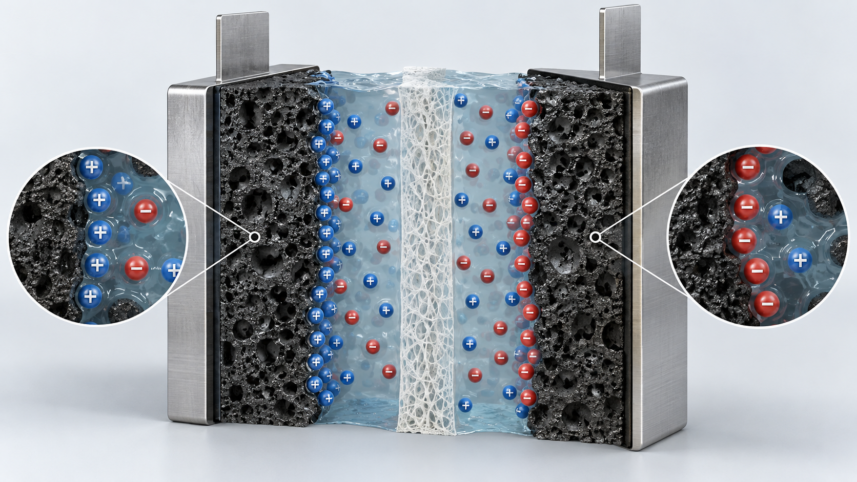
Shapes, colors and dimensions are illustrative. Consult the original schematic below for exact values and label correspondence.
View the original SVG schematic and exact annotations
Reading guide and original schematic labels: An electric double-layer capacitor in the charged state (concept) / + / + / + / + / - / - / - / - / - / + / + / - / Negative electrode / (porous carbon) / Positive electrode / (porous carbon) / Separator / Electrolyte (contains ions) / Current collector (aluminium foil) / Current collector / When charged / - Charge lines up at the / electrode/electrolyte boundary / - Cations are drawn to the negative, / anions to the positive surface / - Ions also enter the pores of the / carbon and line up on its walls / Note: wound cells roll foil coated with electrode material together with a separator [17]; simplified cross-section. / Note: ion sizes, pore shapes and counts are not realistic; solvation shells are omitted.
Nippon Chemi-Con explains that its device uses no chemical reaction and stores energy only by the physical movement of ions to the surface of activated carbon Sourced (the manufacturer's explanation) [Reference 17]. A review, on the other hand, treats pseudocapacitors, which store charge by fast surface redox reactions, as a separate type [Reference 1]. Where “physical adsorption” ends and “reaction” begins changes continuously with the material, the electrolyte and the voltage range (Section 6).
For materials, what matters is that the design goals for the two mechanisms are opposite: adsorption is governed by surface area and pore size, pseudocapacitance by reactive surface sites and the paths for electrons and ions (Commentary).
3. Our calculation: reproducing datasheet numbers from formulas
The datasheet for Skeleton Technologies' SCF3400 cell lists a rated voltage of 3.0 V, a rated capacitance of 3,400 F, a DC 10 ms ESR of 0.12 mΩ, a mass of 0.514 kg and a volume of 0.39 L Sourced (manufacturer's stated values) [Reference 15]. We check whether the stored-energy and power values in the same table can be reproduced with simple formulas.
The formulas are stored energy E = ½ C V² and matched-load maximum power P = V² ÷ (4R), where R is the ESR Our calculation.
- Stored energy: ½ × 3,400 F × (3.0 V)² = 15,300 J = 4.25 Wh (datasheet: 4.25 Wh)
- Specific energy and energy density: 4.25 ÷ 0.514 kg = 8.27 Wh/kg, and 4.25 ÷ 0.39 L = 10.9 Wh/L (datasheet: 8.27 Wh/kg, 10.9 Wh/L)
- Matched-load power: 3.0² ÷ (4 × 0.00012 Ω) = 18.75 kW (datasheet: 18.75 kW). Divided by 0.514 kg, 36.48 kW/kg (datasheet: 36.48 kW/kg)
- Using VR down to VR/2: at 1.5 V, ½ × 3,400 × 1.5² = 3,825 J = 1.06 Wh. What can be drawn is 4.25 − 1.06 = 3.19 Wh (75% of the stored energy). The datasheet's cycle-life condition is also VR to VR/2.
- Raising the rated voltage from 2.7 V to 3.0 V: for the same capacitance, (3.0 ÷ 2.7)² = 1.235, i.e. about 23% more stored energy (the effect on ageing is a separate matter; Section 7).
Assumptions and limits: matched-load power is the theoretical maximum when the load resistance equals the internal resistance, at which point as much power is lost as heat as is delivered (an explanation from circuit theory). It is not an operating point. The 3.19 Wh figure is our estimate assuming capacitance is independent of voltage.
4. A materials engineer's view (1): capacitance is set by the pores ions can enter, not by surface area
The capacitance of a double layer is set by how many ions can line up on the electrode surface, so “large surface area” has long been the goal for materials. But one has to be careful about what a surface-area figure actually measures.
- Theory versus BET: a 2008 paper states that a single graphene sheet has a surface area of 2,630 m²/g, substantially higher than the BET (nitrogen adsorption) values for the activated carbons used in current EDLCs Sourced [Reference 4]. A 2011 paper that made a porous carbon from graphene reports a BET surface area of up to 3,100 m²/g and pore widths of 0.6–5 nm [Reference 5].
- Pores that are too small still work: Chmiola et al. varied the average pore size of carbide-derived carbon from 0.6 to 2.25 nm and measured double-layer capacitance in an organic electrolyte. The result challenged the long-held axiom that pores smaller than the solvated electrolyte ions cannot contribute to charge storage Sourced [Reference 3].
- Ions shed their solvent: a review sums this up: ion desolvation occurs in pores smaller than the solvated ions, and carbon electrodes with subnanometre pores gave higher capacitance [Reference 1].
The BET method derives area from the amount of nitrogen gas adsorbed. Ions in an electrolyte depend on the size they have with their solvent shell, on their charge, and on the shape of the pore entrance, so the surface nitrogen can reach and the surface ions can reach do not coincide. What the reports above show is that the match between pore width and ion size determines capacitance (Commentary).
This has two practical consequences. (1) Evaluate electrode material and electrolyte together: change the electrolyte and the optimum pore width may change. (2) Look at capacitance per volume (F/cm³) as well as per mass (F/g). The latter is the point made in the MXene paper: volume is at a premium in portable devices and vehicles, yet research has mainly focused on improving gravimetric performance Sourced [Reference 9].
5. Electrode material families: activated carbon, graphene, CNTs, MXene, oxides
| Material | Representative report | Reported values (as far as the abstract or document states) | This article's reading |
|---|---|---|---|
| Activated carbon | Nippon Chemi-Con DLCAP catalogue (manufacturer) [17]; Chmiola et al. 2006, Science [3] | Cells wind foil coated with electrode material and use the large surface area of activated carbon (manufacturer's explanation). Carbide-derived carbon with 0.6–2.25 nm pores was studied in an organic electrolyte, showing that pores smaller than the solvated ions also contribute | The mainstream in products. The match between pore width and ion is the key |
| Graphene-based | Stoller et al. 2008, Nano Letters [4]; Zhu et al. 2011, Science [5]; El-Kady et al. 2012, Science [6] | Chemically modified graphene: specific capacitance 135 F/g (aqueous) and 99 F/g (organic). Activated graphene: BET up to 3,100 m²/g, pore width 0.6–5 nm. Laser reduction of graphite oxide films: conductivity 1,738 S/m, specific surface area 1,520 m²/g, no binder or current collector needed | Reports on electrode materials in the laboratory, not cell-level values (Section 6) |
| CNTs | Futaba et al. 2006, Nature Materials [7] | A densely packed, aligned single-walled CNT material made using the “zipping effect” of liquids, which keeps high surface area, flexibility and conductivity and can be used as a supercapacitor electrode | The abstract gives no capacitance figure; we could not confirm one |
| MXene | Lukatskaya et al. 2013, Science [8]; Ghidiu et al. 2014, Nature [9] | Cations from aqueous solution intercalate into Ti3C2, with volumetric capacitance above 300 F/cm³. A “clay” film made with HCl + LiF (tens of micrometres thick) reaches up to 900 F/cm³ | High volumetric capacitance, but film thickness and conditions need checking (Fig. 4) |
| Metal oxides (pseudocapacitance) | Augustyn et al. 2014 [10]; Brousse et al. 2015 [11]; Gogotsi and Penner 2018 [12] | Fast redox reactions at or near the surface aim at high energy even at high charge-discharge rates. MnO2 behaves like a carbon electrode; Ni(OH)2 and cobalt oxides in KOH are classed as battery-type | Whether to call them “pseudocapacitive” is debated (Section 6) |
All Sourced (paper abstracts and the manufacturer's explanation; References 3–12, 17). Values with different conditions placed side by side; they cannot be ranked.
6. A materials engineer's view (2): pitfalls in reading “F/g” in papers
In a 2011 Science perspective, Gogotsi and Simon point out that exceptional performance claims for electrodes in batteries and electrochemical capacitors often fail to hold up when all device components are included Sourced [Reference 13] (we could confirm only the one-sentence summary and could not confirm any specific factor). Stoller and Ruoff likewise say that methods for evaluating electrode materials in the laboratory are not well standardized and that different methods give widely varying results, and they review reliable methods [Reference 14].
Before the capacitance number in a paper, check these five points (this article's organization).
- (1) What is the denominator? Active-material mass only, the whole electrode, or the whole cell? The specific energy in the datasheet (8.27 Wh/kg) is divided by the mass of the whole cell [Reference 15].
- (2) Cell configuration: a two-electrode cell, or a three-electrode (reference electrode) measurement? The abstract says results differ widely with the evaluation method [Reference 14].
- (3) Electrode thickness and density: just as the high volumetric capacitance of hydrated ruthenium oxide is limited to “thin films” [Reference 9], values from thin electrodes need not carry over to thick practical ones.
- (4) Voltage window, current, electrolyte: the window changes greatly with the electrolyte (Section 7). Specific capacitance (F/g) also changes with current and scan rate; Stoller et al. report consistently good performance over a wide range of scan rates [Reference 4].
- (5) Capacitive or battery-type? Check whether the charge-discharge curve or cyclic voltammogram has a capacitor-like shape or battery-like peaks.
What is “pseudocapacitance”? The debate over the name
Pseudocapacitance is described as a faradaic process involving surface or near-surface redox reactions that offers a means of achieving high energy density at high charge-discharge rates Sourced [Reference 10]. Brousse et al. criticize calling every electrode material that uses faradaic reactions “pseudocapacitive”: materials whose electrochemical signature (cyclic voltammogram and charge-discharge curve) resembles that of a “battery”, such as Ni(OH)2 and cobalt oxides in KOH, should not be called pseudocapacitive. Conversely, they say MnO2 is a true pseudocapacitive material because it shows behaviour typical of a capacitive carbon electrode [Reference 11].
Gogotsi and Penner note a growing number of electrode materials, among them transition-metal oxides, hydroxides, sulfides, carbides, nitrides and conducting polymers, whose electrochemical characteristics are neither purely capacitive nor purely faradaic [Reference 12]. From the materials side, “fast” and “capacitive” are different things: the former is a matter of kinetics, the latter of the thermodynamic question of whether charge varies continuously with potential (Commentary).
7. Electrolytes and voltage: energy scales with the square of voltage
Since E = ½ C V², raising the voltage helps as much as raising capacitance, or more. A review names two strategies for raising energy density: introducing pseudocapacitive materials to raise capacitance, and using new electrolytes that allow a higher cell voltage, and it discusses advances in ionic liquids and organic electrolytes Sourced [Reference 2]. The thermodynamic decomposition voltage of water is about 1.23 V, which is the background to the narrow potential window of aqueous electrolytes (an explanation from textbook values).
| Item | Nippon Chemi-Con DLCAP DKJ (85 F) | Skeleton SkelCap SCF3400 | Taiyo Yuden LIC2540R3R8207 |
|---|---|---|---|
| Type | Electric double-layer capacitor (wound) | Supercapacitor (D60, aluminium can) | Lithium-ion capacitor (cylindrical) |
| Rated voltage | 2.7 V (conditions for use at 2.5 V and 2.0 V are also listed) | 3.0 V | Maximum 3.8 (3.5) V, minimum 2.2 V |
| Capacitance | 85 F (typ.) | 3,400 F (rated) | 200 F ±20% |
| Internal resistance | 7.7 mΩ (typ.), 9.2 mΩ max (measurement conditions not confirmed) | ESR (DC 10 ms) 0.12 mΩ (rated) | Less than 0.05 Ω |
| Operating temperature | −40 to +65 °C (2.7 V) / +70 °C (2.5 V) / +85 °C (2.0 V) | −40 to +65 °C | −25 to +70 (+85) °C |
| Life criteria | After 1,500 h at 2.7 V and 65 °C: capacitance change within ±30%, internal resistance within 200% of the upper limit. The same test at 2.5 V and 70 °C for 2,000 h | End-of-life criteria: ESR at 200% of rated, capacitance at 80% of rated. Cycle life 1,000,000 cycles (room temperature, V | No life specification found in the spec sheet we consulted (October 2015 edition) |
All Sourced (manufacturers' stated values: Nippon Chemi-Con catalogue E1009N 2026 [Reference 17], Skeleton datasheet [Reference 15], Taiyo Yuden spec sheet [Reference 18]). Test methods and criteria differ, so they cannot be ranked against each other.
We estimate the energy that can be drawn over the voltage range of the lithium-ion capacitor (LIC), assuming constant capacitance Our calculation.
- LIC2540 (200 F): ½ × 200 × (3.8² − 2.2²) = ½ × 200 × 9.6 = 960 J = 0.267 Wh. Against 1,444 J stored at 3.8 V, that is about 66%.
- EDLC (VR to VR/2): what can be drawn is 75% of the stored energy (Section 3).
Assumptions and limits: in an actual LIC, the relation between voltage and capacitance is not the same as in an EDLC, so constant capacitance is only a rough estimate. Because the minimum voltage is a high 2.2 V, this example shows that the usable fraction is smaller for a similar voltage ratio; it does not rank the LIC against the EDLC. The spec sheet gives no mass, so Wh/kg is not calculated.
In Nippon Chemi-Con's catalogue, the higher the operating temperature, the lower the permitted voltage (2.7 V up to 65 °C, 2.5 V up to 70 °C, 2.0 V up to 85 °C) Sourced [Reference 17]. Raising the voltage to gain 23% more stored energy also raises the electrochemical stress on the electrolyte and the electrode surface (Commentary; the specific degradation mechanisms are not described in the documents we consulted, and we could not confirm them).
The electrolyte is a material that, as a combination of solvent and salt, sets the potential window, conductivity, temperature range and tolerance to impurities (water) at the same time. From a materials viewpoint, the match between the electrolyte and every material it touches (current collectors, sealing materials, separators) may determine life more than improving the electrode material does (Inference; the documents we consulted do not show individual degradation mechanisms).
8. Energy density and power density: reading a Ragone plot with its conditions
A Ragone plot puts specific energy (Wh/kg) on the horizontal axis and specific power (W/kg) on the vertical axis to compare devices. But placing values side by side whose axis definitions, test conditions and mass boundaries differ gives a misleading impression. Here we read a plot drawn only from datasheet values, with their conditions attached.
| Point | Specific energy | Specific power (definition) | Source and conditions |
|---|---|---|---|
| SkelCap SCF3400 | 8.27 Wh/kg (based on rated capacitance) | 36.48 kW/kg (matched load, DC 10 ms ESR) | Skeleton datasheet [15] |
| SkelCap SCX5000 | 11.1 Wh/kg | 28.4 kW/kg (matched load, 10 ms ESR, labelled “for comparison”) / 19.9 kW/kg (matched load, 1 s ESR, labelled “for engineering”) | Skeleton datasheet [15]. It lists both values and distinguishes their uses |
| Amprius SA02 (Li-ion, silicon anode) | 340 Wh/kg (1C discharge, including packaging) | about 1.73 kW/kg (max pulse 55 A, 5C, within 30 s × nominal 3.50 V ÷ 0.1112 kg) Our calculation | Amprius catalogue [21] |
| Amprius SA03 (Li-ion, silicon anode) | 400 Wh/kg (including packaging) | about 1.16 kW/kg (max pulse 34.8 A, 3C × nominal 3.40 V ÷ 0.102 kg) Our calculation | Amprius catalogue [21] |
Datasheet values are manufacturers' stated values. The definition of specific power differs from row to row.
We estimate the size of the energy-density gap from datasheet values alone Our calculation.
- Specific energy: 340 ÷ 8.27 = about 41, and 400 ÷ 8.27 = about 48. For these two products the gap is about 40 to 50 times.
- Matched-load power: the SCF3400's 36.48 kW/kg is about 31 times the SA03's pulse power of 1.16 kW/kg (our calculation), but the definitions differ (matched-load power is a theoretical maximum drawn at 50% efficiency).
Assumptions and limits: the three definitions (matched load, 1 s ESR, pulse current × nominal voltage), the discharge conditions and the mass boundary are not aligned. These ratios are rough figures to give a sense of scale; they say nothing about other companies' products or the limits of future technology.
The SCX5000 datasheet lists the same matched-load power twice: calculated from the 10 ms ESR (labelled “for comparison”) and calculated from the 1 s ESR (labelled “for engineering”) Sourced [Reference 15]. The values are 28.4 kW/kg and 19.9 kW/kg, about 30% apart.
This means that the longer the ESR measurement time (the lower the frequency), the larger the ESR: a power estimated from a short-time resistance cannot be delivered in operation that lasts seconds (Commentary; the physical cause of ESR growing with time is not described in the documents we consulted). When comparing catalogue values, always check which definition of power is used.
9. Applications and limits
The applications that official documents confirm are the following Sourced.
- Power backup: Nippon Chemi-Con lists “suitable for electricity backups” among the features of the DKJ series [Reference 17].
- Peak assist in hybrid vehicles: the international standard IEC 62576:2018 defines test methods for the electrical characteristics of electric double-layer capacitor cells used for peak power assistance in hybrid electric vehicles [Reference 20].
- Industry and infrastructure: Skeleton states on its web page that its clients are in sectors such as AI data centres, the grid, automotive, transportation and defence (the company's own description) [Reference 16].
Limits: what the datasheets show
- Energy density: as Sections 3 and 8 show, it is a few tens of times lower than that of lithium-ion cells Our calculation.
- Voltage is not constant: stored energy is proportional to V² and the voltage falls as the device discharges, so the voltage range the downstream equipment tolerates sets the usable fraction (Fig. 2). The datasheet's cycle-life condition of VR to VR/2 corresponds to this.
- Leakage current: the Skeleton SCF3400 specifies a maximum leakage current of under 8 mA after 72 hours and under 50 mA after 8 hours, at 3.0 V and 25 °C [Reference 15]. For applications that must hold charge for a long time, this value enters the specification.
- Temperature and voltage: as in the previous section, the permitted voltage falls at high temperature [Reference 17].
- Short circuit: the Skeleton datasheet lists the short-circuit current (21.5 kA) “for informational purposes” and notes that it must not be used as an operating current [Reference 15].
Standards
- IEC 62391-1: the generic specification for fixed electric double-layer capacitors for use in electric and electronic equipment. The 2015 edition (edition 2.0) was withdrawn on 20 October 2022 and replaced by the 2022 edition [Reference 19].
- IEC 62576:2018: test methods for the electrical characteristics of electric double-layer capacitors for hybrid electric vehicles (edition 2.0) [Reference 20].
The standards' full texts are paid; we checked only the titles and scope statements. The Skeleton SCX5000 datasheet includes the notation “IEC62391-1” in its ESR entry [Reference 15], but we did not check the test conditions.
10. Strengths, weaknesses and open issues
(1) Strengths
- Low ESR, so very large currents can be moved in and out (0.12 mΩ; 18.75 kW at matched load; manufacturer's stated values) Sourced [Reference 15].
- Withstands a very large number of cycles (1,000,000; room temperature, VR to VR/2; manufacturer's stated value) Sourced [Reference 15].
- Wide operating temperature range (−40 to +65 °C; manufacturers' stated values) Sourced [References 15, 17].
(2) Weaknesses and constraints
- Low specific energy (8.27 Wh/kg; manufacturer's stated value) Sourced [Reference 15].
- The usable voltage range decides how much energy can be drawn (75%, for example) Our calculation.
- The permitted voltage falls at high temperature Sourced [Reference 17].
- The high capacitances in papers are often for the electrode alone, for thin films or in specific electrolytes, which is different from device performance Sourced [References 9, 13, 14].
(3) What we could not confirm
- Representative specific capacitance and BET values of activated carbon: we could not confirm specific figures (F/g, m²/g) for the activated carbons used in products from official documents.
- Performance of commercial cells that use graphene, CNTs or MXene: within what we checked these are laboratory reports, and we could not confirm commercial cell figures. Skeleton lists a proprietary material, “Curved Graphene”, on its product page [Reference 16], but we could not confirm its structure or numbers.
- Degradation mechanisms: the documents we consulted do not describe the specific mechanisms at high voltage and high temperature.
- A quantitative comparison of self-discharge: we confirmed that leakage current is specified, but did not compare across manufacturers or technologies.
- LIC cycle life and mass: not found in the Taiyo Yuden spec sheet (October 2015 edition).
- Stored energy is ½CV². The datasheet's 4.25 Wh, 8.27 Wh/kg and 18.75 kW can be reproduced with this and V²/(4R) Our calculation
- Discharging until the voltage has halved gives 75% of the stored energy Our calculation
- Capacitance is set by “the pores ions can enter”, not by BET surface area. Pores smaller than solvated ions contribute too Sourced
- The high volumetric capacitance of MXene and the 1,000–1,500 F/cm³ of hydrated ruthenium oxide are conditional values (thickness, thin films) Sourced
- An electrode's numbers usually shrink once it is built into a device. Always check the denominator and the configuration Sourced
- Read a Ragone plot with the power definition aligned. Skeleton itself separates “for comparison” from “for engineering” Sourced
11. Glossary
- Supercapacitor
- Umbrella term for electric double-layer capacitors and pseudocapacitors. Also called ultracapacitor or electrochemical capacitor.
- Electric double layer
- A layer in which positive and negative charges face each other at the boundary between electrode and electrolyte.
- EDLC
- Electric double-layer capacitor. It stores charge by ion adsorption.
- Pseudocapacitance
- Energy storage by fast redox reactions at or near the surface; distinguished from battery-type behaviour.
- ESR
- Equivalent series resistance, an indicator of internal resistance. Its value depends on the measurement time or frequency.
- Matched-load power
- The maximum power V²/(4R) when the load resistance equals the ESR. Efficiency at that point is 50%.
- BET surface area
- Specific surface area from the amount of adsorbed nitrogen gas (Brunauer-Emmett-Teller). It does not equal the area ions can reach.
- Desolvation
- An ion shedding its surrounding solvent molecules to enter a small pore.
- MXene
- Two-dimensional layered carbides and nitrides of transition metals, such as Ti3C2.
- Ragone plot
- A chart with specific energy on one axis and specific power on the other, used to compare energy-storage devices.
- Lithium-ion capacitor (LIC)
- A hybrid that combines an electric double-layer electrode with a lithium-based electrode; its voltage range is higher.
- VR
- Rated voltage. Cycle-life conditions are often charge-discharge between VR and VR/2.
- JEITA
- Japan Electronics and Information Technology Industries Association. Its guide on transporting electric double-layer capacitors gives the method for calculating energy.
12. References
- Simon, Gogotsi"Materials for electrochemical capacitors," Nature Materials 7, 845–854 (2008) — doi.org/10.1038/nmat2297
- Béguin, Presser, Balducci et al."Carbons and Electrolytes for Advanced Supercapacitors," Advanced Materials 26, 2219–2251 (2014) — doi.org/10.1002/adma.201304137
- Chmiola et al."Anomalous Increase in Carbon Capacitance at Pore Sizes Less Than 1 Nanometer," Science 313, 1760–1763 (2006) — doi.org/10.1126/science.1132195
- Stoller et al."Graphene-Based Ultracapacitors," Nano Letters 8, 3498–3502 (2008) — doi.org/10.1021/nl802558y
- Zhu et al."Carbon-Based Supercapacitors Produced by Activation of Graphene," Science 332, 1537–1541 (2011) — doi.org/10.1126/science.1200770
- El-Kady et al."Laser Scribing of High-Performance and Flexible Graphene-Based Electrochemical Capacitors," Science 335, 1326–1330 (2012) — doi.org/10.1126/science.1216744
- Futaba, Hata et al."Shape-engineerable and highly densely packed single-walled carbon nanotubes and their application as super-capacitor electrodes," Nature Materials 5, 987–994 (2006) — doi.org/10.1038/nmat1782
- Lukatskaya et al."Cation Intercalation and High Volumetric Capacitance of Two-Dimensional Titanium Carbide," Science 341, 1502–1505 (2013) — doi.org/10.1126/science.1241488
- Ghidiu et al."Conductive two-dimensional titanium carbide 'clay' with high volumetric capacitance," Nature 516, 78–81 (2014) — doi.org/10.1038/nature13970
- Augustyn, Simon, Dunn"Pseudocapacitive oxide materials for high-rate electrochemical energy storage," Energy & Environmental Science 7, 1597 (2014) — doi.org/10.1039/c3ee44164d
- Brousse, Bélanger, Long"To Be or Not To Be Pseudocapacitive?" Journal of The Electrochemical Society 162, A5185–A5189 (2015) — doi.org/10.1149/2.0201505jes
- Gogotsi, Penner"Energy Storage in Nanomaterials – Capacitive, Pseudocapacitive, or Battery-like?" ACS Nano 12, 2081–2083 (2018) — doi.org/10.1021/acsnano.8b01914
- Gogotsi, Simon"True Performance Metrics in Electrochemical Energy Storage," Science 334, 917–918 (2011) — doi.org/10.1126/science.1213003
- Stoller, Ruoff"Best practice methods for determining an electrode material's performance for ultracapacitors," Energy & Environmental Science 3, 1294 (2010) — doi.org/10.1039/c0ee00074d
- Skeleton TechnologiesSkelCap SCF3400 / SCX5000 datasheets (PDF; file name dated 2026-04-02) — skeletontech.com
- Skeleton Technologies"Supercapacitor Energy Storage D60 Cells" (product page) — skeletontech.com
- Nippon Chemi-ConDLCAP supercapacitor catalogue (CAT. No. E1009N 2026, PDF) — chemi-con.co.jp
- Taiyo YudenCylinder Type Lithium Ion Capacitors LIC2540R3R8207 spec sheet (2 October 2015, PDF) — farnell.com (a distributor's copy of the Taiyo Yuden spec sheet)
- IECIEC 62391-1:2015 "Fixed electric double-layer capacitors for use in electric and electronic equipment – Part 1: Generic specification" (IEC Webstore) — webstore.iec.ch
- IECIEC 62576:2018 "Electric double-layer capacitors for use in hybrid electric vehicles – Test methods for electrical characteristics" (IEC Webstore) — webstore.iec.ch
- Amprius Technologies"Product Portfolio Q3 2026" (product catalogue and datasheets, PDF) — amprius.com
13. Claim-to-source audit
| Claim in the text | Basis | Label |
|---|---|---|
| Supercapacitors store charge by ion adsorption (EDLCs) or fast surface redox reactions (pseudocapacitors); ion desolvation occurs in pores smaller than the solvated ions, and carbon electrodes with subnanometre pores gave higher capacitance | Reference 1 (abstract of Simon and Gogotsi 2008) https://doi.org/10.1038/nmat2297 | Sourced |
| Strategies for raising energy density are pseudocapacitive materials and new electrolytes (ionic liquids, organic electrolytes) that raise cell voltage | Reference 2 (abstract of Béguin et al. 2014) https://doi.org/10.1002/adma.201304137 | Sourced |
| Carbide-derived carbon with 0.6–2.25 nm pores was studied in an organic electrolyte, and the result challenged the axiom that pores smaller than solvated ions do not contribute | Reference 3 (abstract of Chmiola et al. 2006) https://doi.org/10.1126/science.1132195 | Sourced |
| A single graphene sheet's surface area of 2,630 m²/g exceeds BET values for activated carbon; specific capacitance 135 F/g (aqueous) and 99 F/g (organic); consistently good performance over a wide range of scan rates | Reference 4 (abstract of Stoller et al. 2008) https://doi.org/10.1021/nl802558y | Sourced |
| Activated graphene-oxide-derived carbon with BET up to 3,100 m²/g, pore width 0.6–5 nm, and high capacitance and energy density in organic and ionic-liquid electrolytes | Reference 5 (abstract of Zhu et al. 2011) https://doi.org/10.1126/science.1200770 | Sourced |
| Laser reduction of graphite oxide films gives conductivity 1,738 S/m and specific surface area 1,520 m²/g, with no binder or current collector needed | Reference 6 (abstract of El-Kady et al. 2012) https://doi.org/10.1126/science.1216744 | Sourced |
| A densely packed single-walled CNT material made with the zipping effect of liquids can be used as a supercapacitor electrode | Reference 7 (abstract of Futaba et al. 2006) https://doi.org/10.1038/nmat1782 | Sourced |
| Cations from aqueous solution intercalate into Ti3C2 MXene, with volumetric capacitance above 300 F/cm³ (higher than porous carbons) | Reference 8 (abstract of Lukatskaya et al. 2013) https://doi.org/10.1126/science.1241488 | Sourced |
| Best carbon electrodes are about 300 F/cm³; hydrated ruthenium oxide reaches 1,000–1,500 F/cm³ only in thin films; MXene “clay” films up to 900 F/cm³; synthesis with HCl + LiF; research has focused mainly on gravimetric performance | Reference 9 (abstract of Ghidiu et al. 2014) https://doi.org/10.1038/nature13970 | Sourced |
| Pseudocapacitance is a faradaic process at or near the surface that offers high energy density at high charge-discharge rates | Reference 10 (abstract of Augustyn et al. 2014) https://doi.org/10.1039/c3ee44164d | Sourced |
| Ni(OH)2 and cobalt oxides in KOH should not be called pseudocapacitive; MnO2 is a true pseudocapacitive material with capacitor-like behaviour | Reference 11 (abstract of Brousse et al. 2015) https://doi.org/10.1149/2.0201505jes | Sourced |
| A growing number of electrode materials show characteristics that are neither purely capacitive nor purely faradaic | Reference 12 (abstract of Gogotsi and Penner 2018) https://doi.org/10.1021/acsnano.8b01914 | Sourced |
| Exceptional performance claims for electrodes often fail to hold up when all device components are included | Reference 13 (summary of Gogotsi and Simon 2011) https://doi.org/10.1126/science.1213003 | Sourced |
| Methods for evaluating electrode materials are not standardized and give widely varying results | Reference 14 (abstract of Stoller and Ruoff 2010) https://doi.org/10.1039/c0ee00074d | Sourced |
| SCF3400: rated voltage 3.0 V, rated capacitance 3,400 F, ESR (DC 10 ms) 0.12 mΩ and (DC 1 s) 0.14 mΩ, stored energy 4.25 Wh, specific energy 8.27 Wh/kg, energy density 10.9 Wh/L, matched-load power 18.75 kW and 36.48 kW/kg, mass 0.514 kg, volume 0.39 L, leakage current (under 8 mA at 72 h, under 50 mA at 8 h), end-of-life criteria (ESR 200%, capacitance 80%), cycle life 1,000,000 (room temperature, VR to VR/2), operating temperature −40 to +65 °C, short-circuit current 21.5 kA (informational). SCX5000: 11.1 Wh/kg; 28.4 kW/kg (10 ms, for comparison) and 19.9 kW/kg (1 s, for engineering); ESR 0.20 mΩ with the IEC62391-1 notation | Reference 15 (Skeleton datasheet; manufacturer's stated values) https://www.skeletontech.com/hubfs/02-DS-2026-04-02-Skeleton-SCF3400%2c%20SCX5000-D60%20supercapacitor-1M.pdf | Sourced |
| SkelCap cells are available at 2.85 V or 3.0 V; Skeleton says its clients are in AI data centres, grid, automotive, transportation and defence; the product page names “Curved Graphene” | Reference 16 (Skeleton product page; the company's description) https://www.skeletontech.com/en/skelcap-supercapacitors | Sourced |
| The explanation that DLCAP uses no chemical reaction and stores energy only by the physical movement of ions to the activated carbon surface; the wound structure of electrode on aluminium foil; DKJ series 2.7 V, 85 F, internal resistance 7.7 mΩ (typ.) and 9.2 mΩ (max), mass 25 g, energy 0.09 Wh, operating temperatures (2.7 V: −40 to +65 °C; 2.5 V: +70 °C; 2.0 V: +85 °C), life-test criteria (2.7 V, 65 °C, 1,500 h; 2.5 V, 70 °C, 2,000 h), and the feature “suitable for electricity backups” | Reference 17 (Nippon Chemi-Con DLCAP catalogue E1009N 2026; manufacturer's stated values) https://www.chemi-con.co.jp/products/relatedfiles/capacitor/catalog/dl-all-e.pdf | Sourced |
| LIC2540R3R8207: maximum 3.8 (3.5) V, minimum 2.2 V, 200 F ±20%, internal resistance under 0.05 Ω, operating temperature −25 to +70 (+85) °C; spec sheet dated 2 October 2015 | Reference 18 (Taiyo Yuden spec sheet; manufacturer's stated values) https://www.farnell.com/datasheets/1972298.pdf | Sourced |
| The title and scope of IEC 62391-1:2015, withdrawn on 20 October 2022 and replaced by the 2022 edition | Reference 19 (IEC Webstore) https://webstore.iec.ch/en/publication/23581 | Sourced |
| The title of IEC 62576:2018 and its scope: test methods for the electrical characteristics of EDLC cells used for peak power assistance in hybrid electric vehicles (edition 2.0) | Reference 20 (IEC Webstore) https://webstore.iec.ch/publication/62711 | Sourced |
| Amprius cells SA02 (340 Wh/kg, nominal 3.50 V, 111.2 g, max pulse 55 A) and SA03 (400 Wh/kg, nominal 3.40 V, 102.0 g, max pulse 34.8 A) | Reference 21 (Amprius product catalogue; manufacturer's stated values) https://amprius.com/documents/Amprius_Product_Catalog.pdf | Sourced |
| 4.25 Wh from ½CV²; 18.75 kW from V²/(4R); 3.19 Wh (75%) from VR to VR/2; about 23% more at 3.0 V than at 2.7 V; the LIC's 0.267 Wh (about 66%); specific-energy gaps of about 41 and 48 times; Amprius specific power of 1.73 and 1.16 kW/kg; a power ratio of about 31 between the SCF3400 and the SA03 | Our calculation. Constant capacitance, matched load, and nominal voltage × max pulse current ÷ mass are all assumptions made in this article. They are rough figures from values with differing definitions and do not rank products or show technology limits. | Our calculation |
| That the thermodynamic decomposition voltage of water is about 1.23 V; that the BET method rests on nitrogen adsorption; that matched-load power is a theoretical maximum at 50% efficiency | Explanations from textbook values and principles (no individual source; commentary) | Commentary |
| That we could not confirm representative specific capacitance or BET values for activated carbon, the performance of commercial cells using graphene, CNTs or MXene, degradation mechanisms at high voltage and temperature, a quantitative comparison of self-discharge, and the LIC's cycle life and mass | Not stated in the documents we opened, so this article does not state them (commentary) | Commentary |
| The reading that “no chemical reaction” is a design philosophy; that pores ions can enter, not surface area, set capacitance; the five checks for reading electrode numbers; the trade-off of voltage against temperature and life; the inference that matching the electrolyte with the materials it touches determines life; the reading of ESR time and power; the grouping of strengths and weaknesses | This article's organization, commentary and inference based on published content; not views stated by the companies or institutions | Commentary |
| That Figs. 1, 2, 3, 4 and 5 are drawings for explanation; that the hero image and Fig. 6 are AI-generated concepts | Note from this article | Commentary |
Last updated: 9 October 2026. Sources are limited to primary material (abstracts and bibliographic data of peer-reviewed papers, manufacturers' datasheets and catalogues, and the pages of IEC standards). Because the article contains structural readings and materials-design interpretations, these are labelled “Commentary” and kept separate from sourced facts. Representative specific capacitance and BET values of activated carbon, the performance of commercial cells using graphene, CNTs or MXene, degradation mechanisms at high voltage and temperature, a quantitative comparison of self-discharge, and the cycle life of LICs could not be confirmed from public primary sources and are therefore not stated. Paper values come from abstracts, and conditions differ from paper to paper. Manufacturers' figures are manufacturers' stated values; test methods differ, so they are not ranked. The calculations in Sections 3, 7 and 8 are rough figures to give a sense of scale. All figures are conceptual illustrations: Figs. 1, 2, 3, 4 and 5 are vector drawings, and the hero image and Fig. 6 are AI-generated concepts. None is an actual cross-section photograph, micrograph or product image.