TECHNOLOGY EXPLAINER
Electrode Manufacturing
— the process decides what the material can do
A lithium-ion electrode is the product of a long sequence: mix powders and polymer into a solvent, coat it thin, dry it, press it, then add liquid and bring the cell to life. Even with the same materials, how you mix, how fast you dry, how hard you press and how you carry out the first charge change the battery you get. The sequence is also uneven in what it costs: drying and solvent recovery are reported to use a large share of the energy, while formation and aging use a large share of the time and cost. To a materials engineer, a battery is a material and also a record of the process that made it.
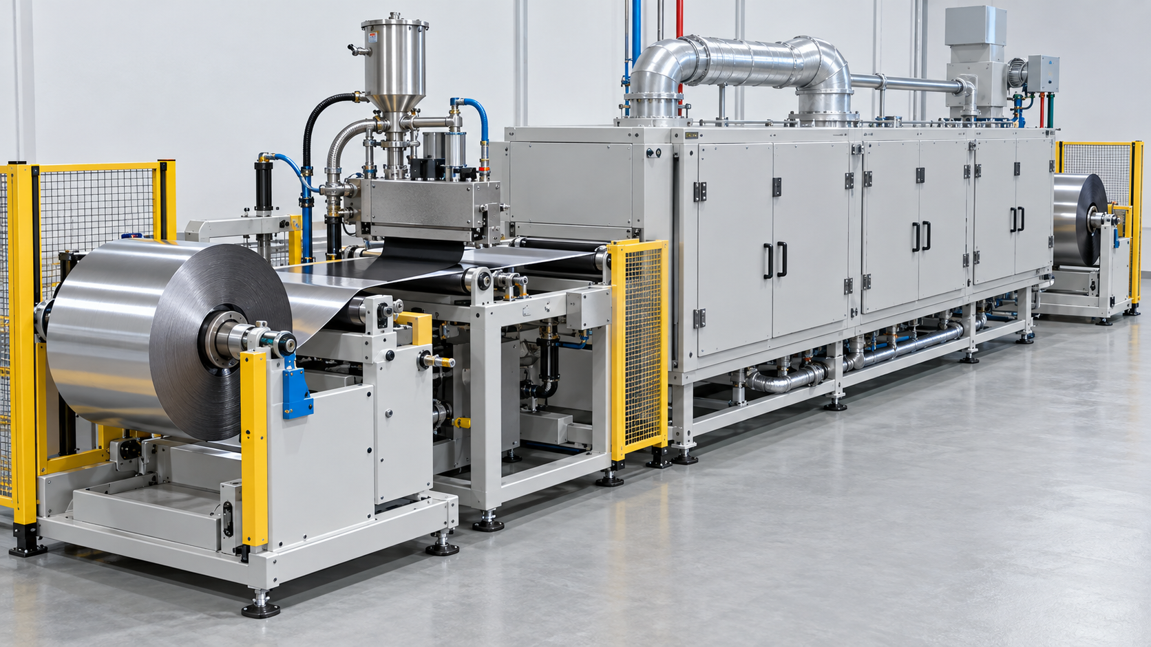
- What electrode manufacturing is (the short version)
- A map of the process — where cost and energy go
- Mixing (slurry) — A materials engineer's view (1): the order of mixing changes the electrode's skeleton
- Coating
- Drying — A materials engineer's view (2): dry fast and the binder floats to the surface
- Solvent recovery for NMP, and the regulation
- Our calculation: how much solvent is dried, and the heat to evaporate it
- Calendering — A materials engineer's view (3): more pressing is not always better
- Slitting, winding / stacking and electrolyte filling
- Formation and aging
- How dry electrodes differ
- What is still hard, and what could not be confirmed
- How to read evaluations and standards
- Glossary
- Primary sources
- Claim-to-source audit
Sourced = a statement in published material (link given)
Our calculation = a figure this article derived, with the assumptions spelled out
Not yet confirmed = a plan or schedule with no confirmed decision or record
Structural readings and materials-design interpretations are marked separately as Commentary. Where a review reports figures from other studies, we say "according to the review".
1. What electrode manufacturing is (the short version)
- How an electrode is made (the wet process): mix active material, conductive additive and binder with a solvent into a slurry, coat it on metal foil and dry it. For the cathode the binder PVdF is usually dissolved in NMP; for the anode, SBR is dispersed in water together with CMCSourced (iScience 2021 review)
- What follows: calendering raises density, slitting trims the width, the electrodes are wound or stacked into a cell, electrolyte is injected, and formation (the first charge and discharge) and aging make the battery usable
- What matters to a materials engineer: the conditions at each step act, through binder distribution, pore structure and the quality of the film (SEI), on capacity, power and life. Performance is set not only by materials but by process history (Commentary)
An electrode is not "a mix of materials" but "something that has passed through mixing, drying and pressing". With the same materials, the mixing order changes how carbon and binder attach, the drying changes how the binder is distributed, and the pressing changes the pore pathways. And within the sequence, drying and solvent recovery take the largest share of energy, and formation and aging a large part of the time and cost, as reported.
2. A map of the process — where cost and energy go
The iScience 2021 review [Source 1] divides lithium-ion cell manufacturing into three parts: electrode preparation, cell assembly and electrochemical activation. A technical column by Daikin Industries [Source 7] describes the same thing as the "front-end process" (making the electrodes) and the "back-end process" (assembling the cell into a battery).
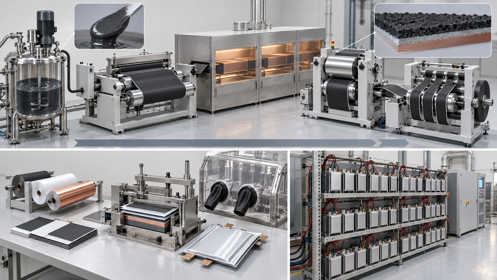
View the original SVG schematic and exact annotations
Where do cost and energy concentrate? Here are two estimates quoted in the review.
What can be read from them follows the review's wording [Source 1]Sourced.
- Cost: electrode coating, drying, cell formation and aging together make 48% of total manufacturing cost; formation and aging alone about 32.6%, the largest single step
- Energy: in measurements at a pilot-scale plant, drying and solvent recovery used about 47% and the dry room about 29%. The reason given is long-duration heating and cooling of the off-gas
- Time: coating, calendering and slitting are roll-to-roll steps running at tens to over a hundred metres a minute, but vacuum drying takes 12 to 30 hours and formation and aging 1.5 to 3 weeks
In other words, cost and energy are concentrated in the steps where you wait (drying, formation, aging) rather than the steps that flow fast and continuously (coating, calendering, slitting) (Commentary).
3. Mixing (slurry) — A materials engineer's view (1): the order of mixing changes the electrode's skeleton
The first step is to mix active material, conductive additive and binder with solvent into a slurry that can be coated. According to the reviews [Sources 1 and 2], the cathode usually uses PVdF dissolved in NMP, and the anode SBR dispersed in water with CMCSourced. Industry today uses planetary mixers to make large volumes of slurry; mixing is about 7.9% of total manufacturing cost and takes 30 minutes to 5 hoursSourced.
The iScience 2025 review [Source 2] describes mixing in two stages: premixing (powder with powder) and main mixing (the slurry). The conventional route disperses each component directly into the solvent; uniform dispersion then needs long stirring or ultrasonication, which costs energy and time, and agglomerates or phase separation may remain. Premixing and pregrinding the powders first is described as reducing reliance on long dispersion in solvent and so reducing processing time and energySourced.
The iScience 2021 review [Source 1] describes a study by Wang et al. (2020)Sourced.
- Order A: add the conductive carbon to the PVdF/NMP solution first, then the active material. → A porous carbon-and-binder network forms between active particles
- Order B: mix the carbon and active material powders first, then add that powder to the PVdF/NMP solution. → After drying, a carbon-and-binder layer coats the surface of the active material
According to the review, the better order (Order A) doubled the ionic conductivity and the 5 C rate performance of an LiNi0.33Mn0.33Co0.33O2 (NMC111) electrodeSourced (a laboratory-scale result quoted by the review, not the performance of production cells).
What this shows is that electrode performance is set by structure as well as by formulation. With an identical recipe, it matters whether conductive additive and binder form a network between particles or a shell around them, because the paths for electrons and ions differ (Commentary). The roles of conductive additives and binders are covered in our explainer on conductive additives and binders.
What happens when solids content goes up
Raising the solids content of the slurry (the mass fraction of powder and polymer excluding solvent) reduces solvent use and drying time. The review [Source 1] notes that a high-concentration slurry has a higher viscosity and may not be coated with a conventional slot die, and that extrusion under pressure has been tried. Ultrasonic mixing can handle high-concentration slurries through the micro-turbulence of collapsing bubbles and is said to use less energy than conventional mixing without external stirringSourced (the original studies were not checked). Slurry viscosity is assessed with a rheometer, measuring viscosity, elasticity and yield pointSourced [Source 2].
4. Coating
The slurry is coated on metal foil (aluminum for the cathode, copper for the anode). The iScience 2025 review [Source 2] lists slot-die, roll-to-roll and comma-bar coating as widely used in industrySourced.
- Slot die: a "pre-metered" method. The flow rate to the die is fixed in advance, which makes film thickness easier to control precisely. Industrial machines are said to run at up to about 300 ft/min (about 90 m/min). On the other hand, edges tend to be heavy, which can cause trouble at cell assembly
- Comma bar and roll-to-roll: "self-metered" methods in which the gap sets the thickness. Suited to intermittent coating
- Coating thickness: currently 50 to 300 µm, with thicker electrodes (40 to 50 mg/cm2, over 700 µm) being sought. The gap between die and foil must be widened, but too wide a gap makes liquid spill upstream and the coating uneven, so staying inside the coating window is important
- Coat weight: with simultaneous double-sided coating and similar methods, 70 to 300 g/m2 after drying can be controlled with edges sharper than 3 mm, it is said
All Sourced (iScience 2025 review [Source 2]; speeds and coat weights are from machine makers' descriptions and count as manufacturers' stated values). The Daikin column [Source 7] gives the thickness of the active-material layer made by coating as 50 to 100 µm per side.
Coating is where a variation in concentration or thickness at any point turns directly into a variation in electrode performance. The review also says that variations in the microstructure of the coating or the distribution of the slurry strongly affect cell performance, and non-uniform coating impairs Li-ion transportSourced.
5. Drying — A materials engineer's view (2): dry fast and the binder floats to the surface
The coated film passes through a long oven that drives off the solvent. According to Daikin's column [Source 7], NMP-based cathodes are dried at 120 to 130 °C, which uses a lot of energySourced. The boiling point of NMP is about 202 °C (public data aggregated by PubChem; Daikin's column gives about 204 °C)Sourced. Daikin also says that for the anode, the latent heat of evaporation of water is large, so drying energy is surprisingly large even with a water-based processSourced.
The paper by Dorn et al. (Communications Chemistry, 2026) [Source 3] explains in its introductionSourced.
- In wet drying, capillary-driven convection and solvent evaporation can carry the PVdF binder and conductive additive (together the "carbon-binder domain") toward the outer (surface) side of the electrode
- This non-uniform distribution impairs contact between particles and between particles and current collector, leading to higher electronic resistance, lower adhesion and faster capacity fade
- The solids content of the paste and the way it is dried affect how easily this movement occurs. Earlier work has linked the depth distribution of binder to the drying temperature
The paper compares two NCM622 cathode formulations and shows that a sample with pronounced binder migration and a reference sample can be told apart by the depth profile of fluorine (glow discharge sector-field mass spectrometry). It adds, however, that even the reference sample showed a detectable sign of binder moving toward the surface, reading this as meaning that some movement is unavoidable as long as solvent is evaporatedSourced.
From the materials side, this can be read as the binder's molecular size, its solubility in the solvent and its tendency to adsorb on particle surfaces being the flip side of how easily the film dries. The process wants faster drying to save energy and time; the electrode wants binder left evenly. The two collide. Binder design is also design for surviving fast drying (Commentary).
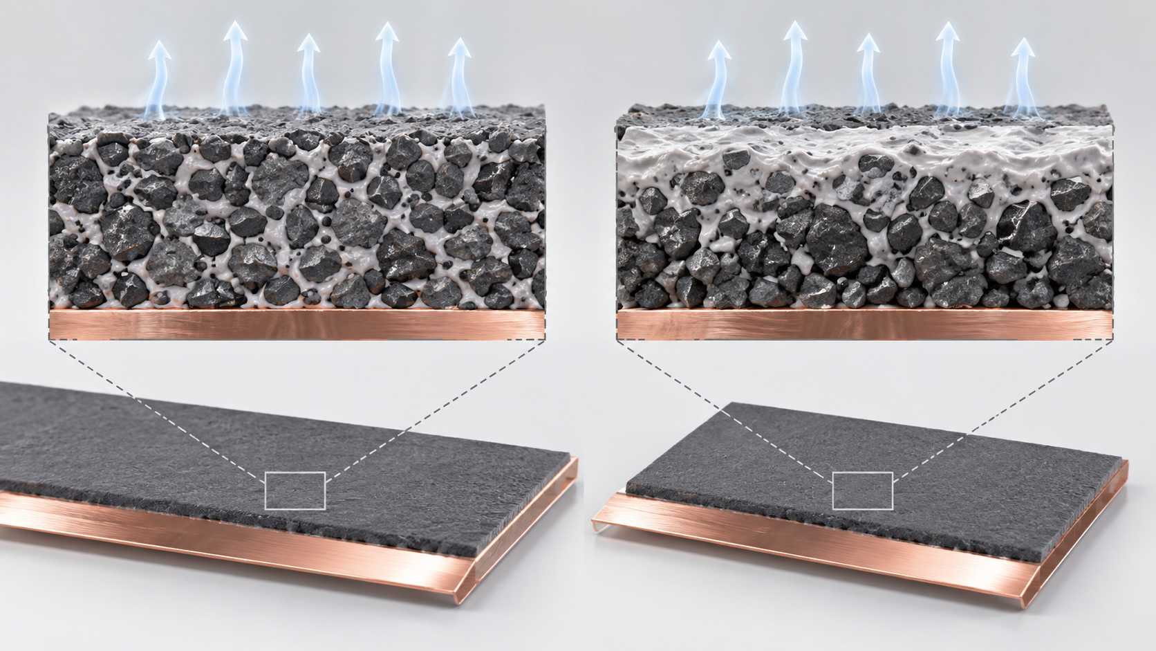
View the original SVG schematic and exact annotations
Over-drying has its own pitfall
Before the cell is assembled, electrodes are vacuum-dried to remove residual water. When LiPF6 meets water, HF forms and can damage the active material and lower performance [Source 1]Sourced. The review says vacuum drying is often done at 60 to 150 °C for 12 hours or moreSourced.
Yet "less water is better" does not always hold. In a comparison by Huttner et al. (2019) described in the review, long vacuum drying at 120 °C gave the lowest water content but the worst electrochemical performance, while a 20-minute argon purge at room temperature (20 °C) gave the highest capacity in both rate and cycling testsSourced (laboratory scale). The authors suggest that long, hot drying may weaken the bonding of PVdF and CMC/SBR and damage the electrode structure, and that a water content of about 326 ppm (after argon purging) still gave good performance, and that a little water may even help the SEI form and stay stableSourced. Drying is a step that keeps the binder in good condition as well as removing water (Commentary).
6. Solvent recovery for NMP, and the regulation
NMP, used in the wet cathode process, is flammable, so the factory building needs to be explosion-proof, and because it is costly it is not burned but must be recoveredSourced (Daikin [Source 7]). The iScience 2021 review says the NMP evaporated in drying is condensed, then distilled and reused, and cites a report (Ahmed et al., 2016) of 20 to 30% loss in this reuseSourced. The iScience 2025 review, on the other hand, describes an integrated system from a machine maker (Dürr) that it says gives 99% NMP recovery and 95% reusable solvent after distillationSourced (a manufacturer's stated value; conditions not confirmed). The two figures may differ in what they cover and how they are defined, and are not for ranking against each other.
Regulation: NMP is restricted in Europe
NMP (1-methyl-2-pyrrolidone) is restricted under the EU chemicals regulation REACH. Commission Regulation (EU) 2018/588 (18 April 2018, Official Journal L 99/3) added the following as entry 71 of Annex XVII to REACHSourced [Source 5].
- Scope: NMP on its own and in mixtures containing 0.3% or more NMP. The recitals state that mixtures with 0.3% or more NMP are classified as toxic for reproduction, category 1B under the CLP Regulation (EC) No 1272/2008
- Content: after 9 May 2020, NMP may not be placed on the market unless the chemical safety report and safety data sheet include worker-exposure derived no-effect levels (DNELs) of 14.4 mg/m3 by inhalation and 4.8 mg/kg/day dermal, and it may not be manufactured or used unless risk-management measures keep worker exposure below those DNELs
- Exception: use as a solvent or reactant in wire coating has a later start, 9 May 2024
So the regulation's stage is adopted and applyingSourced. It does not ban the use of NMP; it imposes a duty to keep worker exposure below a set level. For a battery plant that keeps using NMP, closed handling and recovery become premises of the equipment design (Commentary).
Regulation of NMP outside the EU, such as in Japan or the United States, was not checked in this article.
7. Our calculation: how much solvent is dried, and the heat to evaporate it
Let us look at the energy of drying by order of magnitude. First, find the amount of solvent from the solids content.
Assumptions Our calculation
- Slurry solids content (mass fraction excluding solvent) of 50%, 60% and 70% (our illustrative values, not real formulations)
- Latent heat of NMP: 127.3 kcal/kg = about 533 kJ/kg = about 0.148 kWh/kg (HSDB record, via PubChem [Source 6])Sourced
- The electrical energy stored by 1 kg of dry coating is about 0.57 kWh, taking 96% active material, 160 mAh/g specific capacity and 3.7 V average voltage (all our assumptions)
Calculation (per 1 kg of dry coating)
- Mass of NMP: (1 − solids) ÷ solids = 1.00 kg at 50%, 0.67 kg at 60%, 0.43 kg at 70%
- Minimum heat to evaporate it: × 0.148 kWh/kg = 0.148 / 0.099 / 0.063 kWh
- Ratio to the energy the coating stores: ÷ 0.57 kWh = about 26% / 17% / 11%
Reading: raising the solids content from 50% to 70% cuts the solvent to be dried by about 57%. The latent heat alone is on the order of one to two tenths of the electrical energy the cathode coating stores. A real oven also heats air, handles exhaust and condenses and distils the solvent, so it uses more (Commentary). Assumptions and limits: the solids content, stored energy and coating composition are all our assumptions. The calculation does not cover a real line, a real cell or drying of the (water-based) anode.
Assumptions Our calculation
- Measurements at a pilot-scale plant for a 32 Ah LMO/graphite cell, from Table 1 of the iScience 2021 review [Source 1] (citing Yuan et al., 2017). Energy consumption per cell: drying and solvent recovery 6.22 kWh, dry room 3.9 kWh, all steps together 13.28 kWhSourced
- Take the average cell voltage as 3.8 V (our assumption) → the electrical energy the cell stores is 32 Ah × 3.8 V = about 0.12 kWh
Calculation
- Total 13.28 kWh ÷ 0.12 kWh = about 110 times
- Drying and solvent recovery alone: 6.22 ÷ 0.12 = about 50 times
Reading: in the pilot-scale measurement, the electricity used to make one cell was of the order of a hundred times the energy the cell stores. Assumptions and limits: the value is quoted from a small pilot plant running at low utilisation, not a mass-production plant. Mass production is likely to be lower, but that figure could not be confirmed in this article. The units and denominators of the original paper (Yuan et al.) were not checked directly. Read it as an example for a sense of scale.
8. Calendering — A materials engineer's view (3): more pressing is not always better
The dried coating is pressed by rollers (calendering). According to the iScience 2025 review [Source 2], calendering reduces the porosity of the coating by 20 to 40%, raises density and electronic conductivity, improves adhesion to the current collector and smooths the surfaceSourced. It is a small step in cost, about 5% of the total [Source 1], but it fixes the physical character of the electrode.
The harder you press, the more active material fits in a given volume. But the pores are also where electrolyte enters and Li ions travel. The review says that over-calendering shortens diffusion paths but also cracks particles and fuses interfaces, inviting side reactions and shorter lifeSourced [Source 2]. A study combining numerical simulation and machine learning (quoted by the review) reports that tortuosity depends strongly on the initial porosity and the calendering pressureSourced [Source 1].
The binder shows up in calendering conditions too. Thermoplastic PVdF deforms elastically more readily as temperature rises, and the review says that the higher the rolling temperature, the lower the porosity and compaction resistance and the higher the adhesion strengthSourced [Source 1]. On the other hand, high-temperature calendering above 120 °C is not recommended because it can reduce capacitySourced [Source 2]. The review also mentions a prediction (discrete element simulation) that the electrode can recover elastically by up to 17% after the pressure is removedSourced [Source 1].
The limit of calendering can also be moved from the material side. A paper by Raju et al. (Energy & Environmental Science, 2026) [Source 4] exploits the ability of single-crystal LiNi0.8Mn0.1Co0.1O2 (SC-NMC811) to be calendered to higher packing density than conventional cathodes: electrodes calendered to 25% porosity were laser-drilled with holes and still averaged under 30% porosity while showing better rate performanceSourced (laboratory scale). As background, the same paper states that the commercial target for electrode porosity is 35% or lowerSourced. Polycrystalline secondary particles crack easily when pressed, whereas single crystals withstand heavy calendering — particle design and calendering conditions are decided together (Commentary).
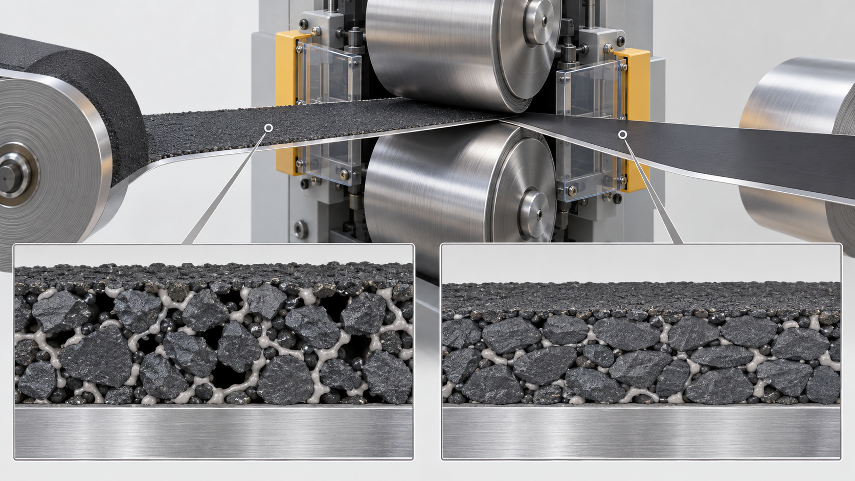
View the original SVG schematic and exact annotations
9. Slitting, winding / stacking and electrolyte filling
The calendered electrode is cut to the required width by slitting. It is a low-cost step (about 3.1% of manufacturing cost) at 80 to 150 m/min, using blades or chisels, and laser cutting is also usedSourced [Source 1]. The electrodes and separator are then wound or stacked in the dry room to form the inside of the cell, aluminum and copper tabs are welded on, and the stack is placed in its casingSourced [Source 1].
Filling — until the liquid reaches every corner
The electrolyte is injected before sealing. The iScience 2025 review [Source 2] describes this step as followsSourced.
- It typically takes 12 to 24 hours in the dry room until the electrolyte saturates every void of the anode, cathode and separator
- Wetting is defined as the ratio of electrolyte that has entered the pores to the total pore volume. To engage capillary action, pressure is varied during and after filling. Lowering the pressure in the cell below atmospheric (for example 100 mbar) is also common to shorten wetting
- If wetting is poor, the SEI may not form uniformly on the active particles in the first charge, which can lead to electrolyte decomposition, lower Coulombic efficiency and the start of lithium dendrite growth
- For large prismatic and cylindrical cells, filling is done in several doses, and the process can take up to three weeks in some cases
The Ishikawa review listed "wetting of electrodes and separator" as an important additive function (Chapter 3 of our explainer on electrolytes and separators); this is the step whose time it would shorten (Commentary). And because a calendered, lower-porosity electrode is harder for liquid to enter, calendering and filling make opposing demands on the same structure, the pores (Commentary).
10. Formation and aging
A filled cell cannot yet be used. In formation, the first charge and discharge, the SEI is built on the anode surface. The iScience 2021 review [Source 1] describes it as followsSourced.
- The potential of the graphite anode (0 to 0.25 V vs. Li/Li+) is lower than the reduction potential of the electrolyte (about 1 V), so the electrolyte decomposes during formation and aging and the SEI forms
- If the formation current or temperature is too high, only a porous SEI forms and cannot keep electrolyte from the anode. Continued decomposition consumes limited lithium and capacity fades. A dense, stable SEI usually takes several charge-discharge cycles at a low rate (for example C/20), with the rate raised gradually
- High-current formation can lead to lithium plating on the graphite surface
- The gas produced is released for safety. Aging, in which cells sit on shelves during or after formation, completes electrolyte penetration and stabilises the SEI. Aging doubles as a check on self-discharge
As seen in our explainer on electrolytes and separators, components of the electrolyte such as VC, FEC and LiFSI are material for the SEI. It is in the factory's formation step that they are actually consumed and become a film. So designing an electrolyte formulation and designing the formation conditions are one and the same job (Commentary). When the materials are merely assembled, the battery is unfinished; only after formation does it become a battery with a film made jointly by anode and electrolyte.
Formation takes time. In a BatPaC-model estimate, formation and aging account for about 32.6% of manufacturing cost and take up to 1.5 to 3 weeksSourced [Source 1]. Attempts to shorten it have been reported. Two studies described in the review point in opposite directionsSourced.
| Study (as quoted in the review) | Cell | Proposal | Result (laboratory scale) |
|---|---|---|---|
| Lee et al. (2004) | LiCoO2 / graphite | Lower the upper charge voltage from 4.2 V to 3.7 V | Formation time can be halved. SEI formation is claimed to be mostly complete by 3.7 V. No significant difference in cycling stability or Coulombic efficiency |
| Wood et al. (An et al., 2017) | NMC / graphite pouch cell | Hold that the main SEI-forming reactions occur at high states of charge, and repeat cycles in the high-SOC range of 3.9 to 4.2 V | Finished in about 14 hours, 8.5 times faster than the conventional three cycles at 0.05 C. Performance not impaired |
All Sourced (quoted by the iScience 2021 review [Source 1]; the original papers were not opened directly for this article). These are laboratory-scale results under different conditions and are not a basis for deciding which is right.
The review also mentions a report (Heimes et al., 2019) that applying a mechanical load during formation shortened it by about 20%, and another that higher temperature gave only a limited reductionSourced. What can be read from this is that the best formation conditions differ with the combination of cell materials (Commentary).
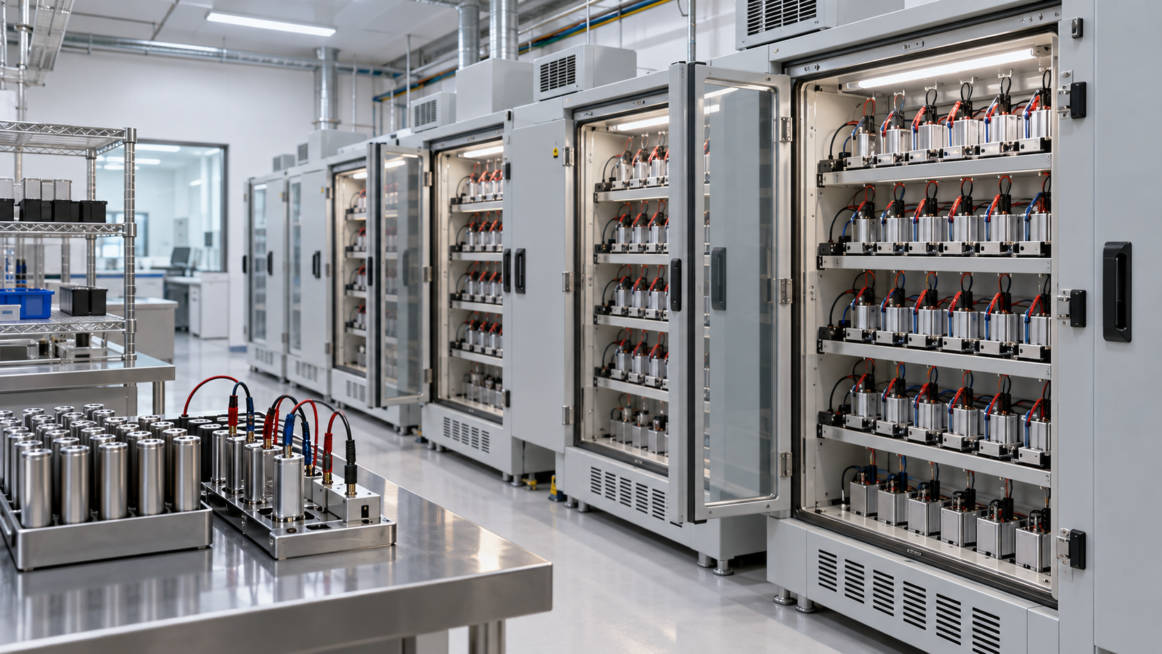
11. How dry electrodes differ
Our explainer on dry electrodes covers ways of making electrodes without solvent. Laid over the map of the process above, what the dry electrode removes is drying and solvent recovery, the step that used about 47% of the energy in the pilot-scale measurement [Source 1]. What remains, even with dry electrodes, are calendering (hot rolling and pressing), winding or stacking, filling, formation and aging. The iScience 2021 review also describes solvent-free electrodes that are hot-calendered or hot-pressed after dry depositionSourced [Source 1].
In short, dry processing replaces part of the sequence, not electrode manufacturing as a whole. In particular, the time of formation and aging (about a third of the cost) and the wetting problem at filling remain in another form (Commentary). Quantitative reductions could not be confirmed in primary sources within the scope of this article (the same as the statement in our dry-electrode explainer).
12. What is still hard, and what could not be confirmed
(1) Cost and energy by step are estimates under different assumptions and small-scale measurements
The values in Fig. 3 are two quotations with different assumptions: a BatPaC model estimate and measurements at a pilot-scale plant for 32 Ah cells. Actual figures for cost and energy by step at a mass-production plant could not be confirmed in this article.
(2) The quantitative link between drying conditions and binder migration
It was confirmed that binder migration relates to drying temperature and solids content, but how much segregation occurs at what temperature and line speed could not be confirmed within the scope of this article.
(3) NMP regulation outside the EU; water-based cathodes
NMP regulations in Japan and the United States were not checked here. Attempts to make cathodes from water-based slurries (by PPG and others) are mentioned in the review [Source 1], but details were not checked.
(4) Original papers cited by the reviews were not opened
Wang (2020), Huttner (2019), Lee (2004), Wood (2017), Yuan (2017), Nelson (2019), Ahmed (2016) and others are cited through the reviews' descriptions; the original papers were not opened directly. The figures are treated as reported by the reviews.
- An electrode carries the history of how it was mixed, dried and pressed. In one example the mixing order doubled the ionic conductivity and rate performance of an NMC111 electrode (laboratory scale)Sourced
- Drying and solvent recovery use about 47% of energy in a pilot-scale measurement. Formation and aging make about 33% of manufacturing cost in an estimateSourced
- In drying, capillary flow can carry binder toward the surface. It can cause lower adhesion and capacity lossSourced
- NMP is restricted in Europe (Regulation (EU) 2018/588, entry 71). Adopted and applying; it imposes a duty to lower worker exposureSourced
- Raising solids from 50% to 70% cuts the NMP to be dried by about 57%. The latent heat alone is one to two tenths of the energy the coating storesOur calculation
- Calendering lowers porosity by 20 to 40%, but too much cracks particles and shortens life. The commercial porosity target is 35% or lowerSourced
- Formation is where electrolyte additives become the SEI. Studies on shortening it point in opposite directionsSourced
13. How to read evaluations and standards
Before comparing which number is larger, align the basis of comparison in the following order. This is an editorial reading checklist, not a set of test conditions or acceptance limits prescribed by a standard.
- 1. What was measured?
- loading, thickness/density variation, yield and production speed. Check the units and whether the result describes a material, component or complete system.
- 2. Under which conditions?
- slurry formulation, drying, web width, line speed, calendering and inspection coverage. Treat results under different conditions as separate results before comparing them.
- 3. The comparison trap
- Do not convert pilot-line results directly into production yield or cost.
- 4. What does the standard cover?
- Check the identifier, title, edition and scope in the issuing body’s material. Distinguish test methods, safety, interoperability and management requirements. Naming a standard alone does not establish that a test, conformity assessment or certification has been completed.
Keep a comparison note containing the object, units, conditions, sample count and variation, comparator, standard edition and unresolved points. Do not invent numerical conditions or acceptance limits from a public abstract of a standard.
14. Glossary
- Slurry
- A muddy mixture of powder dispersed in a solvent. Used to coat electrodes.
- NMP
- N-methyl-2-pyrrolidone. The organic solvent that dissolves PVdF in cathode slurries. Boiling point about 202 °C.
- PVdF
- Polyvinylidene fluoride. The usual cathode binder.
- CMC / SBR
- Carboxymethyl cellulose / styrene-butadiene rubber. The usual water-based anode binders.
- Slot-die coating
- Coating by extruding slurry through a narrow slit onto the foil. A "pre-metered" method: the flow rate sets the thickness.
- Binder migration
- The movement of binder (and conductive additive) toward the surface during drying.
- Calendering
- Pressing the dried coating with rollers to adjust density and porosity.
- Porosity
- The fraction of an electrode's volume that is void. It provides the paths for ions.
- Tortuosity
- How winding the pores of an electrode are. The larger it is, the harder it is for ions to pass.
- Dry room
- A room with strictly controlled moisture. Cell assembly and filling take place here.
- Formation
- The first charge and discharge after filling. It builds the SEI on the anode surface.
- Aging
- Storing cells under set conditions after formation. It serves electrolyte penetration, SEI stabilisation and a self-discharge check.
- DNEL
- Derived no-effect level. Under REACH, a level of exposure below which no health effect is expected for workers.
15. Primary sources
- Y. Liu, R. Zhang, J. Wang, Y. Wang "Current and future lithium-ion battery manufacturing", iScience 24(4), 102332 (2021) (review) — pmc.ncbi.nlm.nih.gov
- A. Nekahi et al. "Advanced lithium-ion battery process manufacturing equipment for gigafactories: Past, present, and future perspectives", iScience 28, 112691 (2025) (review) — pmc.ncbi.nlm.nih.gov
- S. L. Dorn et al. (MEET Battery Research Center, University of Münster) "Fast method for assessing binder migration in lithium-ion battery electrodes using glow discharge-sector field-mass spectrometry", Communications Chemistry (2026) — pmc.ncbi.nlm.nih.gov
- K. Raju et al. "Enhancing power density and cycle life of NMC811 battery cathodes via combined dense calendering and laser patterning", Energy & Environmental Science (2026) (title as shown in the index record) — pmc.ncbi.nlm.nih.gov
- European Commission "Commission Regulation (EU) 2018/588 of 18 April 2018 amending Annex XVII to Regulation (EC) No 1907/2006 ... as regards 1-methyl-2-pyrrolidone" (Official Journal L 99/3, 19 April 2018) — eur-lex.europa.eu
- PubChem (U.S. National Library of Medicine) 1-Methyl-2-pyrrolidone (aggregated data including boiling point and latent heat) — pubchem.ncbi.nlm.nih.gov
- Daikin Industries "Battery materials column: dry processes for lithium-ion batteries" (in Japanese) — daikinchemicals.com
16. Claim-to-source audit
| Claim in the text | Basis | Type |
|---|---|---|
| That manufacturing divides into electrode preparation, cell assembly and electrochemical activation; that the cathode usually uses PVdF in NMP and the anode SBR dispersed in water with CMC; that coating is on both sides with a slot die (aluminum and copper foil); that evaporated NMP is condensed, distilled and reused with a 20 to 30% loss (quoting Ahmed et al.) | iScience 2021 review (Liu, Zhang, Wang)[Source 1] https://pmc.ncbi.nlm.nih.gov/articles/PMC8050716/ | Sourced |
| The division into a front-end process (making electrodes) and a back-end process (assembling the cell); that NMP-based cathode drying is at 120 to 130 °C, that NMP is flammable and needs an explosion-proof building, that NMP recovery equipment and costs are needed, that for the anode the latent heat of water makes drying energy surprisingly large; that NMP boils at about 204 °C; that the active-material layer is 50 to 100 µm per side | Daikin Industries technical column (in Japanese)[Source 7] https://www.daikinchemicals.com/jp/magazine/report-column-lithium-ion-battery-03.html | Sourced |
| That the boiling point of NMP is about 202 °C and its latent heat of vaporisation 127.3 kcal/kg (HSDB) | HSDB and ICSC records aggregated by PubChem[Source 6] https://pubchem.ncbi.nlm.nih.gov/compound/13387 | Sourced |
| That mixing is about 7.9% of total manufacturing cost and 30 minutes to 5 hours, and that planetary mixers are used in industry; that high-concentration slurries have high viscosity and may not be coated with a conventional slot die and extrusion has been tried; that ultrasonic mixing suits high-concentration slurries and uses less energy than conventional mixing (original studies not checked) | iScience 2021 review[Source 1] https://pmc.ncbi.nlm.nih.gov/articles/PMC8050716/ | Sourced |
| The study by Wang et al. (2020): adding carbon to the PVdF/NMP solution first gives a porous carbon-binder network, mixing carbon and active material first gives a carbon-binder layer on the active material, and the better order doubled the ionic conductivity and 5 C rate performance of an NMC111 electrode | iScience 2021 review (quoting Wang et al.; laboratory scale)[Source 1] https://pmc.ncbi.nlm.nih.gov/articles/PMC8050716/ | Sourced |
| The division into premixing (powder with powder) and main mixing (slurry); that direct dispersion in solvent takes long stirring or ultrasonication and may leave agglomerates or phase separation; that premixing and pregrinding are described as reducing reliance on long dispersion and so time and energy; that viscosity is measured with a rheometer (viscosity, elasticity, yield point) | iScience 2025 review (Nekahi et al.)[Source 2] https://pmc.ncbi.nlm.nih.gov/articles/PMC12268664/ | Sourced |
| That slot-die, roll-to-roll and comma-bar coating are widely used; that the slot die is pre-metered, runs at up to about 300 ft/min and tends to give heavy edges; that comma-bar and roll-to-roll are self-metered; that thickness is 50 to 300 µm with 40 to 50 mg/cm2 and over 700 µm being sought and a coating window; that coat weight of 70 to 300 g/m2 with edges under 3 mm can be controlled; that Dürr offers an integrated system with 99% NMP recovery and 95% reusable solvent (manufacturer's stated value) | iScience 2025 review[Source 2] https://pmc.ncbi.nlm.nih.gov/articles/PMC12268664/ | Sourced |
| That variation in the microstructure of the coating or the distribution of slurry strongly affects cell performance and non-uniform coating impairs Li-ion transport | iScience 2025 review[Source 2] https://pmc.ncbi.nlm.nih.gov/articles/PMC12268664/ | Sourced |
| Cost: coating, drying, formation and aging 48% of manufacturing cost, formation and aging about 32.6% (BatPaC, 67 Ah NMC622/graphite cell, plant making 100,000 packs a year). Energy: drying and solvent recovery about 47% and the dry room about 29% (pilot-scale plant, 32 Ah LMO/graphite cell, quoting Yuan et al.). Speeds of coating, calendering and slitting, vacuum drying of 12 to 30 hours, formation and aging of 1.5 to 3 weeks | Table 1 of the iScience 2021 review (quoting Nelson et al. and Yuan et al.; originals not checked)[Source 1] https://pmc.ncbi.nlm.nih.gov/articles/PMC8050716/ | Sourced |
| That capillary-driven convection and evaporation during drying can carry PVdF binder and conductive additive toward the electrode surface; that this leads to higher electronic resistance, lower adhesion and faster capacity fade; that earlier work linked the depth distribution of binder to drying temperature; that even the reference sample showed detectable migration and controlled evaporation still draws some binder to the surface | Dorn et al., Communications Chemistry (2026)[Source 3] https://pmc.ncbi.nlm.nih.gov/articles/PMC13598097/ | Sourced |
| That residual water and LiPF6 form HF; that vacuum drying is often at 60 to 150 °C for 12 hours or more; the Huttner et al. (2019) comparison (120 °C long vacuum drying gave the lowest water but the worst performance; a 20-minute argon purge at 20 °C gave the highest capacity); that long, hot drying may weaken binder bonding; that about 326 ppm water still gave good performance and a little water may help the SEI | iScience 2021 review (quoting Huttner et al.; laboratory scale)[Source 1] https://pmc.ncbi.nlm.nih.gov/articles/PMC8050716/ | Sourced |
| That Regulation (EU) 2018/588 (18 April 2018, OJ L 99/3) added entry 71 (NMP) to REACH Annex XVII; that mixtures with 0.3% or more NMP are classified toxic for reproduction category 1B under CLP; that after 9 May 2020 NMP may not be placed on the market without DNELs of 14.4 mg/m3 (inhalation) and 4.8 mg/kg/day (dermal) in the safety report and data sheet, and exposure must be kept below the DNELs; that wire-coating use starts on 9 May 2024 | Official Journal text on EUR-Lex[Source 5] https://eur-lex.europa.eu/legal-content/EN/TXT/HTML/?uri=CELEX:32018R0588 | Sourced |
| That NMP per 1 kg of dry coating is 1.00, 0.67 and 0.43 kg at 50, 60 and 70% solids; that the minimum heat to evaporate it is 0.148, 0.099 and 0.063 kWh, about 26, 17 and 11% of the energy the coating stores (about 0.57 kWh); that raising solids from 50% to 70% cuts the solvent to dry by about 57% | Our calculation. The solids contents and the 96% active material, 160 mAh/g and 3.7 V are our assumptions. The latent heat of NMP is the HSDB record (PubChem)[Source 6] https://pubchem.ncbi.nlm.nih.gov/compound/13387 | Our calculation |
| That the pilot-scale measurement (6.22 kWh for drying and solvent recovery, 3.9 kWh for the dry room, 13.28 kWh for all steps, per cell) is about 110 times the energy a cell stores (about 0.12 kWh = 32 Ah × 3.8 V), and about 50 times for drying and solvent recovery alone | Our calculation. The energy consumption figures are from Table 1 of the iScience 2021 review (original not checked); the average voltage of 3.8 V is our assumption[Source 1] https://pmc.ncbi.nlm.nih.gov/articles/PMC8050716/ | Our calculation |
| That calendering lowers the porosity of the coating by 20 to 40% and raises density, electronic conductivity and adhesion; that over-calendering causes particle fracture and interface fusion, side reactions and shorter life; that hot calendering gives higher compaction and less rebound but above 120 °C is not recommended because of lower capacity; that two-roll systems are mainly used | iScience 2025 review[Source 2] https://pmc.ncbi.nlm.nih.gov/articles/PMC12268664/ | Sourced |
| That calendering is about 5.19% of cost; that a higher rolling temperature lowers porosity and compaction resistance and raises adhesion (elastic deformability of PVdF); a prediction of up to 17% elastic recovery; that tortuosity depends strongly on the initial porosity and the calendering pressure; that slitting is at 80 to 150 m/min and about 3.09% of cost | iScience 2021 review[Source 1] https://pmc.ncbi.nlm.nih.gov/articles/PMC8050716/ | Sourced |
| That SC-NMC811 can be calendered to higher packing density than conventional cathodes, and that an electrode calendered to 25% porosity and laser-drilled with holes kept an average porosity under 30% and showed better rate performance (laboratory scale); that the commercial target for electrode porosity is 35% or lower | Raju et al., Energy & Environmental Science (2026)[Source 4] https://pmc.ncbi.nlm.nih.gov/articles/PMC12875191/ | Sourced |
| That filling takes 12 to 24 hours; the definition of wetting; the use of varying pressure and a reduced pressure of about 100 mbar; that poor wetting can make the SEI non-uniform; that large cells can take up to three weeks | iScience 2025 review[Source 2] https://pmc.ncbi.nlm.nih.gov/articles/PMC12268664/ | Sourced |
| The description of formation (graphite potential 0 to 0.25 V against the electrolyte reduction potential of about 1 V, several cycles at a low rate such as C/20, lithium plating at high current, release of gas, the role of aging); that formation and aging are about 32.6% of cost and take up to 1.5 to 3 weeks | iScience 2021 review; iScience 2025 review[Source 1] https://pmc.ncbi.nlm.nih.gov/articles/PMC8050716/[Source 2] https://pmc.ncbi.nlm.nih.gov/articles/PMC12268664/ | Sourced |
| That Lee et al. (2004) halved formation time by lowering the upper voltage from 4.2 to 3.7 V; that Wood et al. (An et al., 2017) finished formation 8.5 times faster, in about 14 hours, by repeating cycles at 3.9 to 4.2 V; that Heimes et al. (2019) shortened it by about 20% with mechanical load | iScience 2021 review (quoted; laboratory scale; originals not checked)[Source 1] https://pmc.ncbi.nlm.nih.gov/articles/PMC8050716/ | Sourced |
| That solvent-free electrodes that are hot-calendered or hot-pressed after dry deposition are described | iScience 2021 review[Source 1] https://pmc.ncbi.nlm.nih.gov/articles/PMC8050716/ | Sourced |
| The reading that electrode performance is set by structure; that cost and energy are concentrated in the waiting steps; that binder design is also design for fast drying; the opposing demands of pores for filling and calendering; that formation is where electrolyte additives are consumed and that formulation and formation conditions are one job; that dry processing replaces part of the sequence; the reading on single crystals and calendering | Commentary by this article | Commentary |
| Actual cost and energy by step at mass-production plants, the quantitative link between binder migration and drying conditions, NMP regulation outside the EU, and the original papers cited by the reviews (Wang, Huttner, Lee, Wood, Yuan, Nelson, Ahmed and others) | Could not be confirmed within the scope of this article, so not stated. Figures are treated as reported by the reviews | Commentary |
| That Figs. 2 to 6 are explanatory drawings rather than real factories, electrodes or measurements, and that Figs. 1 and 7 are AI-generated images | Our note | Commentary |
Last updated 10 October 2026. Sources are limited to primary material (peer-reviewed reviews and papers, the Official Journal text of an EU regulation, public databases and a company's technical column). Because the article includes structural readings and materials-design interpretations, those are marked as Commentary and kept separate from sourced fact. Actual cost and energy by step at mass-production plants, the quantitative link between binder migration and drying conditions, and NMP regulation outside the EU could not be confirmed in published primary sources and are not stated. The original papers cited by the reviews were not opened directly, and their figures are treated as reported by the reviews. The calculations in Chapter 7 are illustrative examples with assumptions of our own, not measurements. All figures are explanatory concept graphics. Figs. 2 to 6 are vector drawings; Figs. 1 and 7 are AI-generated images, and none of them shows a real factory, electrode or measurement result.