TECHNOLOGY EXPLAINER
Electrolytes and Separators
— a liquid that would decompose, protected by a film
Inside a lithium-ion battery, the electrolyte carries the ions and the separator keeps the positive and negative electrodes apart. Both look modest next to the electrodes, but the electrolyte is a liquid that cannot survive at the anode, and is used only because the film it forms there protects it. The separator is a membrane designed to melt and close its own pores when it gets hot, switching the cell off. Each is a component whose weakness has been built into the design. The PFAS regulation now being debated in Europe touches both.
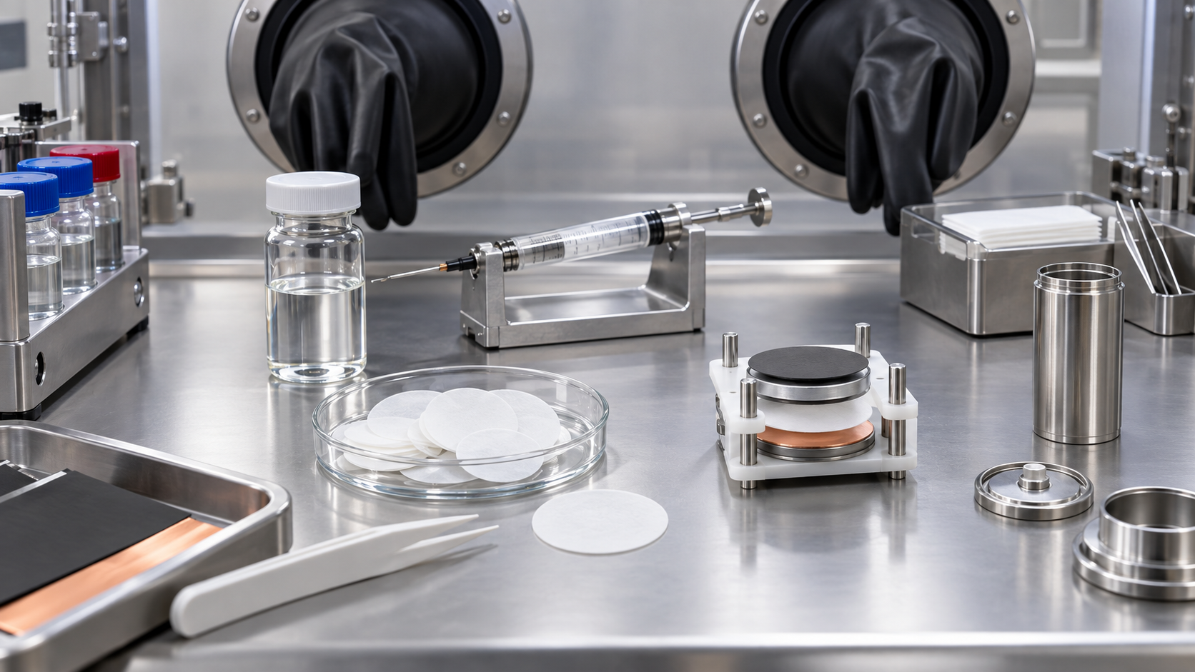
- What electrolytes and separators are (the short version)
- Where the liquid and the films sit inside a cell
- What is in an electrolyte — solvents, salts, additives
- A materials engineer's view (1): why solvents are mixed
- The weakness of LiPF6 and hydrofluoric acid (HF) / Our calculation
- Flammability and gas generation
- SEI and CEI — part of electrolyte development is film development
- Separators — materials and how the pores are made
- A materials engineer's view (2): the pores are there to stop the cell, not only to pass ions
- Heat-resistant coatings
- The PFAS regulation (keeping the stages apart)
- A materials engineer's view (3): the weight of changing a material
- What is still hard, and what could not be confirmed
- How to read evaluations and standards
- Glossary
- Primary sources
- Claim-to-source audit
Sourced = a statement in published material (link given)
Our calculation = a figure this article derived, with the assumptions spelled out
Not yet confirmed = a plan or schedule with no confirmed decision or record
Structural readings and materials-design interpretations are marked separately as Commentary. Manufacturers' values are called "manufacturer's stated value".
1. What electrolytes and separators are (the short version)
- Electrolyte: typically the lithium salt LiPF6 at roughly 1 mol/L (1 M) dissolved in a mixed solvent of ethylene carbonate (EC) and a low-viscosity linear carbonate (DMC, DEC or EMC)Sourced
- Separator: a porous membrane between the electrodes. In Asahi Kasei's words, a member that lets lithium ions through while blocking contact between positive and negative electrodes to prevent short circuitsSourced
- What they share: both are materials used with a weakness in hand. The electrolyte cannot withstand the anode on its own, and the polyolefin that the separator is made of melts at a little over 100 °C
The electrolyte is designed on the assumption that it decomposes; the separator on the assumption that it melts. At the anode, the products of first-charge decomposition form a film that stops further decompositionSourced, and when the temperature rises the separator melts, closes its pores and tries to stop the currentSourced. That "stopping" does not necessarily work the same way in a large battery, however.
2. Where the liquid and the films sit inside a cell
Seen from the side, a cell is a stack: anode (graphite and similar), separator, cathode. The electrolyte soaks into the pores of the electrodes and the pores of the separator, and a thin film formed from the liquid sits on the surface of each electrode. The film on the anode is called the SEI (solid electrolyte interphase); the one on the cathode is the CEI (cathode electrolyte interphase). Our explainer on the SEI covers it in detail, so here we only fix its position.
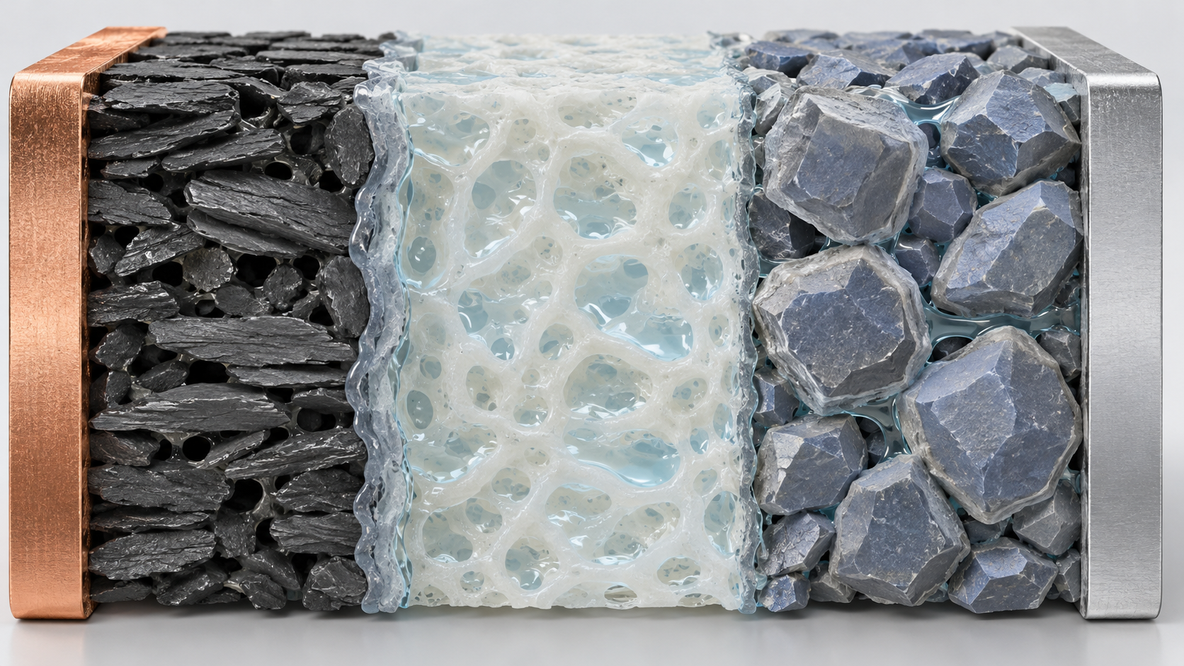
View the original SVG schematic and exact annotations
3. What is in an electrolyte — solvents, salts, additives
An electrolyte has three kinds of ingredient: solvents, a lithium salt and additives. The review by Masashi Ishikawa of Kansai University [Source 1] summarises the present state and recent progress as follows.
| Component | Typical examples | What the review says (in brief) |
|---|---|---|
| Solvent | EC, DMC, DEC, EMC | A typical electrolyte is LiPF6 at about 1 M in a mixed solvent of EC and a low-viscosity solvent. DMC, DEC and EMC are the most widely used low-viscosity solvents |
| Salt | LiPF6 (mainstream), LiFSI, LiBF4, LiClO4 | Today's electrolytes are almost entirely LiPF6; LiBF4 and LiClO4 are used only in small amounts as additives that influence the SEI. LiFSI is described as particularly promising |
| Additives (anode) | VC, FEC, LiBOB and others | VC polymerises reductively on graphite to form the SEI and is expected to improve capacity retention over cycling. FEC contributes to an LiF-rich SEI with strong protective effect and suits silicon-based anodes, but can also cause gas generation |
| Additives (other) | Biphenyls, flame retardants, acid scavengers, wetting aids | Biphenyls polymerise on the cathode and, in larger amounts, give overcharge protection by blocking the polymerisation path. Flame-retardant components are often used less as additives than as solvent components, at 10% or more. Wetting aids are expected to improve productivity of large EV cells and, by preventing uneven electrolyte distribution, lifetime |
All Sourced (Ishikawa, GS Yuasa Technical Report [Source 1]). The review notes that specific additive formulations are often not published, being the manufacturer's know-how.
Additives work in small amounts, but they can also work too well. On VC, the review says it may raise a cell's internal resistance, so the amount added needs particular care for long-storage and EV batteriesSourced. On LiBOB, it says the salt is weak against oxidation and dissolves very poorly in the electrolyte, so the best conditions are hard to set and it is comparatively difficult to use wellSourced.
4. A materials engineer's view (1): why solvents are mixed
EC, essential to forming the film on the anode, is in fact a solid at room temperature. Its melting point is recorded as 36.4 °C and its flash point as 143 °C (open cup)Sourced (PubChem, which aggregates public records; Sources 11 to 13). DMC, by contrast, has a flash point of 18 °C (open cup), and DEC 25 °C (closed cup)Sourced.
So the mixture pairs "EC, which dissolves the Li salt thanks to its high permittivity and is the lead player in the film" with "linear carbonates, which keep the mixture liquid and lower the viscosity so ions move more easily" (Commentary). The review itself says electrolyte development has proceeded by gradual modification of EC-based electrolytes, and that demands such as long life, high voltage, high and low temperature operation, fast charge and discharge and safety often conflict with one another, so they are not easy to meetSourced.
Adding more linear carbonate lowers viscosity, but it also moves the mixture toward a larger share of the more flammable components. Safety entering into the trade-off with viscosity is the core difficulty of this material (Commentary).
Change the salt and the solvent mix changes — the case of LiFSI
The review compares electrolytes based on LiFSI (lithium bis(fluorosulfonyl)imide) with LiPF6-based ones. The key point is that LiFSI dissociates so well that ionic conductivity is maintained even when the EC fraction is cut sharply.
| Electrolyte (Table 1 of the review) | Viscosity (mPa s) | Ionic conductivity (mS cm-1) |
|---|---|---|
| LiPF6 / EC:DMC = 1:1 | 3.64 | 11.3 |
| LiFSI / EC:DMC = 1:1 | 3.39 | 12.1 |
| LiFSI / EC:DMC = 1:9 | 1.89 | 11.2 |
All Sourced (Table 1 of the Ishikawa review [Source 1]). The measurement temperature, and whether the solvent ratios are by volume or by mass, could not be confirmed from the text. The abstract gives "1 M LiFSI" as an example.
The review further reports that with LiFSI/EC:DMC = 1:9 a graphite anode charges and discharges without trouble (first-cycle efficiency, normal cycling efficiency and discharge capacity are almost the same as with LiPF6/EC:DMC = 1:1) and that polarisation at 10 C was the smallestSourced. With LiPF6/EC:DMC = 1:9, by contrast, SEI formation does not proceed well and charging and discharging a graphite anode is practically impossibleSourced. In short, with a different salt, the same solvent ratio decides whether a film forms at all (Commentary).
This comparison rests on laboratory data: half-cells with a graphite anode and a lithium metal counter electrode, and graphite / LiNi1/3Mn1/3Co1/3O2 full cellsSourced. It is not a figure that guarantees life or safety in production cells. One practical concern with LiFSI electrolytes is the effect on the aluminum current collector (Chapter 5).
5. The weakness of LiPF6 and hydrofluoric acid (HF) / Our calculation
LiPF6 is overwhelmingly the mainstream salt, yet it is awkward to handle. The Ishikawa review says the following.
LiPF6 is hard to call thermally stable: from around 80 °C in the electrolyte, hydrolysis by residual water and the decomposition reactions that follow accelerate. Even so, it remains suitable as an electrolyte because it has a wide electrochemical window in which it is not oxidised or reduced, because the trace hydrofluoric acid (HF) produced by hydrolysis contributes to forming a good SEI on the anode, and because the fluoride ions released by decomposition prevent corrosion, especially pitting, of the aluminum cathode current collectorSourced
HF has two faces: culprit and helper. A Nature Catalysis paper by Argonne National Laboratory, BMW, the Technical University of Munich and others [Source 3] treats HF as a highly detrimental product formed by the reaction of trace water with LiPF6, and states that HF in the electrolyte not only affects SEI formation but also causes dissolution (corrosion) of oxide cathode materials and inactive cell componentsSourced. The same paper reports how LiF, a main component of the SEI, can form through the electrochemical conversion of HF into LiF and H2Sourced.
Our calculation: how much HF can 20 ppm of water produce?
Assumptions Our calculation
- Consider only Eq. (1), PF5 + H2O → 2HF + POF3 (2 mol of HF per mol of water)Sourced (the equation is from [Source 3]). Further hydrolysis of POF3 is not included (it gives fewer HF per water molecule, so 2 is the upper side of the estimate)
- 1 kg of electrolyte, 1 M LiPF6, density 1.2 g/mL (the density is our assumption) → about 0.83 mol of LiPF6
- Molar mass of water 18.0 g/mol; of HF 20.0 g/mol
Calculation (water at 20 ppm)
- Water: 20 mg ÷ 18.0 g/mol = 1.11 mmol
- HF (maximum): 1.11 × 2 = 2.22 mmol → × 20.0 = about 44 mg (about 44 ppm)
- LiPF6 consumed (maximum): 1.11 mmol ÷ 830 mmol = about 0.13%
Reading: each 1 ppm of water can give at most about 2.2 ppm of HF by mass. The salt barely diminishes, yet HF appears at the level of tens of ppm (Commentary). Assumptions and limits: in a real cell, much of the water is also adsorbed on electrode and separator surfaces and does not all react here. The calculation is for grasping, by order of magnitude, why water control is demanded so strictly; it does not predict the HF concentration of a real cell.
LiFSI and the aluminum current collector
Turn around the Ishikawa review's point that fluoride from LiPF6 decomposition protects aluminum foil, and it follows that a salt with a different fluorine source needs attention on the aluminum side. Xia et al. studied binary-salt electrolytes mixing LiFSI and LiPF6 and reported that electrolytes with an LiFSI concentration below 0.3 mol/L passivated the aluminum current collector at 4.3 V (vs. Li/Li+) and also improved cycling performanceSourced [Source 6]. In graphite / NMC111 pouch cells with an electrolyte of 0.2 mol/L LiFSI plus 1.0 mol/L LiPF6, capacity retention after 360 cycles at 1 C is reported as 93.9%Sourced (a result from laboratory-scale cells in that paper). That LiFSI appears as a small addition rather than a full replacement can be read as one example of care for the aluminum collector (Commentary).
6. Flammability and gas generation
The electrolyte is an organic solvent, so it burns. Flash points are recorded in public databases as follows.
| Solvent | Flash point (recorded) | Note |
|---|---|---|
| DMC (dimethyl carbonate) | 18 °C (open cup) | Value from the ILO-WHO International Chemical Safety Card (ICSC). HSDB gives 14 °C (closed cup) and 18 °C (open cup) |
| DEC (diethyl carbonate) | 25 °C (closed cup) | Value from ICSC and HSDB |
| EC (ethylene carbonate) | 143 °C (open cup) | Value from HSDB. Melting point 36.4 °C |
| EMC | — | Not found on the PubChem pages consulted for this article |
All Sourced (records from ICSC and HSDB aggregated by PubChem [Sources 11 to 13]). A flash point changes with the test method (closed or open cup).
The flash points of the linear carbonates are near room temperature or below. Add the state of charge, the temperature, the mixing ratio and the presence of salt (which changes vapour pressure), and "the flash point of the electrolyte" cannot be given as a single number. This article could not confirm primary data on the flash point of mixed electrolytes, so it gives values for the individual solvents only.
Directions for flame retardancy
The Ishikawa review says flame-retardant components are an important function for keeping cells safe; they are often used less as additives than as solvent components, at 10% or more, and representative ones are partially fluorinated alkyl ethers, organophosphorus compounds and phosphazenesSourced. Put differently, flame retardancy is not a matter of a small addition but of moving the solvent composition itself (Commentary).
Where does gas come from?
When the electrolyte decomposes, gas is produced. Michalak et al. (Scientific Reports, 2015) observed gas evolution in operating pouch cells directly by neutron imaging. The paper opens by saying that gas generation from electrolyte decomposition is one of the major issues for high-performance rechargeable batteries, and for high-voltage LiNi0.5Mn1.5O4 / graphite cells concludes that metal dissolution and decomposition products formed at high potential worsen gas generation, particularly in the first charge (during graphite SEI formation)Sourced [Source 5].
Heat also decomposes it. Campion et al. identified, as products of heating 1.0 M LiPF6 carbonate electrolytes, CO2, ethylene, dialkyl ethers, alkyl fluorides, OPF3 and fluorophosphates, among othersSourced [Source 4]. They also report that trace protic impurities give rise to fluorophosphates that autocatalytically decompose LiPF6 and the carbonates, that DEC leads to ethylene and that EC leads to oligoethylene oxidesSourced. Here too, a "trace impurity", water, is where the chain starts.
The causes of battery fires and thermal runaway, and assessments of particular products or incidents, are outside the scope of this article. Thermal runaway is covered in our explainer on thermal runaway and battery safety. This article gives only published data on material properties (flash points, decomposition products).
7. SEI and CEI — part of electrolyte development is film development
The story so far leads to the story of films. The Ishikawa review defines the SEI as an electronically insulating, ion-permeable electrode interface film formed from the reductive decomposition products of the electrolyte at first charge, which prevents further decompositionSourced. Our explainer on the SEI frames this as the passivation view: thermodynamically unstable but protected by a kinetic barrier.
Here we confirm that the ingredients of the electrolyte are the material of the film (Ishikawa review; each is Sourced).
- EC: takes part in forming the SEI on carbon anodes and is the lead player in stabilising the anode
- LiPF6: the trace HF from hydrolysis contributes to SEI formation
- LiFSI: FSI acts as a fluorine source at the graphite interface in early cycles and is said to form an LiF-rich SEI on graphite
- VC: polymerises reductively to form the SEI, and is said to polymerise oxidatively on the cathode too, forming a protective film
- FEC: contributes to an SEI rich in LiF with a strong protective effect
On the CEI at the cathode, the review says that additives for the cathode have less academic information and there is no clear concept of an SEI-like film as on the anode, so there are few general guidelines and each case must be judged separatelySourced. In other words, the anode film has reached the stage where it can be spoken of as a design target, whereas the cathode film is still at the stage of being checked combination by combination (Commentary).
8. Separators — materials and how the pores are made
The separator is a membrane that physically separates the electrodes while letting ions through. According to an explainer by Christopher J. Orendorff of Sandia National Laboratories [Source 2], most commercial separators for small batteries (under 3 Ah) are single- or multilayer films of polyolefin, usually polyethylene (PE) or polypropylene (PP), with transition temperatures of about 135 °C for PE and about 165 °C for PP (somewhat dependent on molecular weight)Sourced. As typical values the explainer gives porosity above 40%, thickness around 25 µm, ionic resistivity of 1.5 to 2.5 Ω cm2 and puncture strength above 300 g/mil, and notes that films as thin as 12 to 20 µm exist but lose a great deal of mechanical strengthSourced (an explainer from 2012). Thinner means easier ion transport but less strength — the trade-off between mechanical robustness and an open, porous structure is the starting point of separator design.
Wet and dry — two ways of making pores
Asahi Kasei explains that a dry-process separator has PP as its main component and is made without solvent, while a wet-process separator has PE as its main component, is formed with a plasticizer, and has that plasticizer extracted with a solventSourced [Source 8]. The company makes both the wet-process "Hipore" and the dry-process "Celgard" separators for lithium-ion batteriesSourced [Source 10]. A review by Li et al. (Polymers, 2023) [Source 7] describes how the pores form.
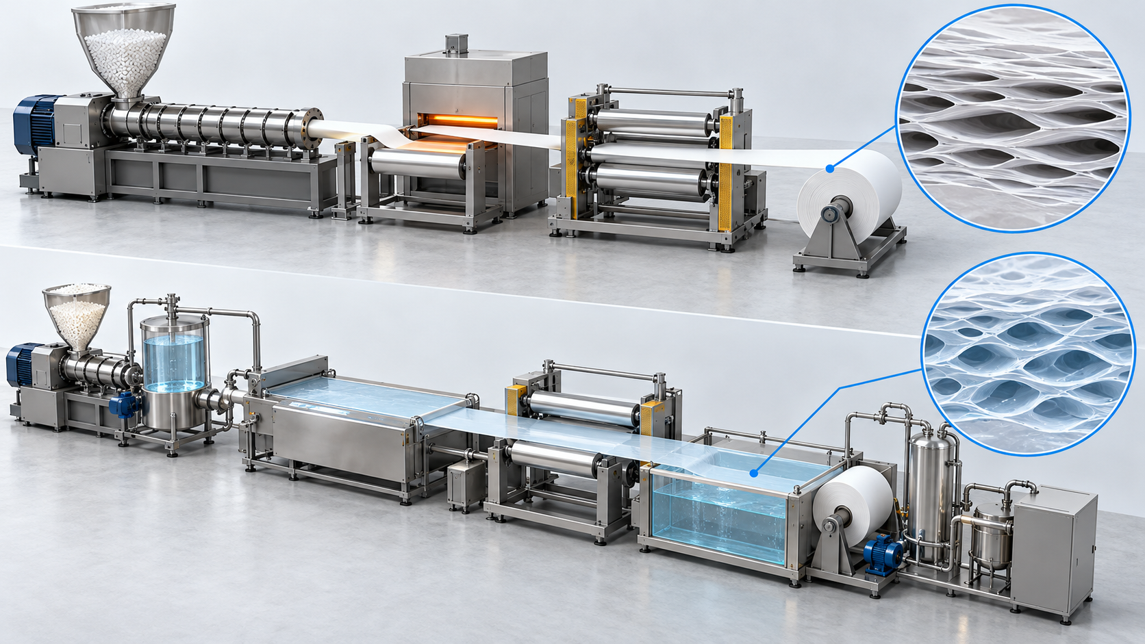
View the original SVG schematic and exact annotations
According to the review, the dry process is generally "melt extrusion and stretching": the extruded film is annealed to raise crystallinity, cold stretching splits the crystal lamellae to seed micropores, hot stretching grows the voids, and heat setting fixes the structureSourced. The wet process is "thermally induced phase separation (TIPS)": PE is made homogeneous at high temperature with a low-molecular-weight solvent (paraffin oil is the most common), extruded and cooled so the phases separate, stretched biaxially, and the solvent is extractedSourced. The review states that wet-process PE film has similar tensile strength in the machine and transverse directions, whereas uniaxially stretched dry-process PP film differs greatly in strength between the two directions and tears easilySourced.
| Product (as named then) | Construction | Process | Thickness | Porosity | Melting temperature |
|---|---|---|---|---|---|
| Entek Teklon | Single-layer PE | Wet extrusion | 25 µm | 38% | 135 °C |
| Exxon Tonen | Single-layer PE | Wet extrusion | 25 µm | 36% | 135 °C |
| Degussa Separion | Ceramic / PET / ceramic | Wet-laid nonwoven mat | 25 µm | above 40% | 220 °C |
| Celgard 2325 | PP / PE / PP trilayer | Dry extrusion | 25 µm | 41% | 134 / 166 °C |
Table I of Orendorff [Source 2] (values from each company's datasheet, Sourced). These are values from a 2012 explainer, not current product specifications. They are not a basis for comparing today's products.
Assumptions Our calculation: thickness 25 µm, porosity 41% (the stated value for Celgard 2325 in the table above), area 1 m2. All pores are assumed to be filled with electrolyte.
- Volume of the film: 2.5×10-3 cm × 104 cm2 = 25 cm3
- Pore volume: 25 cm3 × 0.41 = about 10 cm3 (about 10 mL)
Reading: the pores of 1 m2 of this film can hold at most about 10 mL of electrolyte. What a film actually holds depends on pore shape, wettability and compression. The reason the Ishikawa review lists "wetting of electrodes and separator" as an important additive function is, we read, that getting liquid quickly into these pores bears on productivity of large batteries (Commentary).
9. A materials engineer's view (2): the pores are there to stop the cell, not only to pass ions
According to Orendorff, many multilayer separators have a shutdown function. Two layers have different transition temperatures; as the temperature rises, the lower-melting component melts and fills the pores of the other layer, stopping ion transport and currentSourced. PE (about 135 °C) melts and closes the pores while PP (about 165 °C) keeps the shape as a skeleton — the difference in melting points of the materials becomes the safety mechanism itself (Commentary).
The mechanism has recorded limits, however. The overcharge tests he describes give three resultsSourced.
- The ideal case: an LiCoO2 18650 cell overcharged at 1 C. At a cell temperature of 135 °C (215% state of charge) the separator shut down, the cell became resistive, the voltage rose to the 12 V limit and the cell cooled safely
- An NCA 18650 cell (1 C): shutdown occurred at a can temperature of 125 °C (170% state of charge), but with the test's voltage limit set at 20 V the current kept flowing, leading to an internal short circuit and thermal runaway
- An LiCoO2 cell (2 C): when the cell reached the shrinkage temperature (110 °C) it short-circuited internally and went into thermal runaway
The explainer says these outcomes change greatly with small changes in test conditions (voltage limit, charge rate), and points out that shutdown separators were first designed for low-voltage (under 20 V), small (under 10 A) consumer batteries, so in higher-voltage, larger batteries the shutdown function may not be as robustSourced. The literature it cites (Roth et al.) also shows that after shutdown a separator can pass 200 mA at a 20 V hold-off and 350 mA at 30 VSourced.
Large cells add another problem. Large-area cells heat unevenly, so only part of a cell may shut down, or only some pores may close (incomplete shutdown), concentrating current in the pores that stay open, the explainer notesSourced.
For closing the gap between separator shrinkage or melting and the runaway temperature of the cell, the explainer describes two ways of thinking. One is shutdown at or below 80 °C (though, in batteries with many cells in series, leakage current could still be a problem); the other is dropping shutdown and raising thermal stabilitySourced. Each has advantages and costs, and the explainer's summary is that this is an area still under study in the battery safety community.
10. Heat-resistant coatings
One practical way to raise thermal stability is to coat a polyolefin film with ceramic or similar material. Asahi Kasei explains that "Hipore" comes in two types, a polyolefin microporous film (base film) and a film with ceramic or similar material coated on the base film (coated film), and in 2023 announced a substantial increase in coating capacitySourced [Source 9].
Orendorff's explainer gives numbers for the advantages of ceramic composite filmsSourced.
- An Al2O3-PET composite film shrank only 4% after 1 hour at 105 °C, against 14% for PE film (citing work by Choi et al.)
- In the comparison by Roth et al., the polyolefin shutdown film shut down at 135 °C and degraded and shorted at 165 °C, whereas the impedance of the ceramic/PET film stayed stable to above 220 °C
- In 1 C overcharge tests of NCA / graphite 18650 cells, the cell with a polyolefin separator short-circuited and went into thermal runaway at 135 °C (170% state of charge), while the cell with the composite separator did not run away until 180 °C, the cathode decomposition temperature, at 300% (1.2 M LiPF6 in EC:PC:DMC = 1:1:3, test conditions above 20 V)
The explainer adds that these are results under specific test conditions and that further evaluation is needed to quantify what newer films add to safetySourced. It also says that stacking ceramic as a layer calls for care about delamination between dissimilar layers, and that embedding ceramic in UHMWPE (ultra-high-molecular-weight polyethylene) at over 60% ceramic content may avoid delamination and crackingSourced.
The Li et al. review describes a study comparing Al2O3 and boehmite (γ-AlOOH) as ceramic particles coated on PE film, in which the boehmite system, with its polar hydroxyl (–OH) groups, strengthened the interaction between coating and PE base and raised electrolyte uptake and wettability. It also states that the microstructure of the coating affects deformation and thermal shutdown under abuseSourced [Source 7]. Because a coating adds a layer on top of the pores, added thickness and pore blockage are trade-offs to be weighed in design (Commentary; no specific figures were confirmed within the scope of this article).
11. The PFAS regulation (keeping the stages apart)
Fluorine-containing materials are common around electrolytes and separators. Here we sort out whether the comprehensive restriction on PFAS (per- and polyfluoroalkyl substances) being processed in Europe reaches them, keeping the stages of proposal, evaluation and decision apart.
Which stage are we at?
| Stage | What it is | Status (as far as could be confirmed on 10 October 2026) |
|---|---|---|
| 1. Proposal | The authorities of Denmark, Germany, the Netherlands, Norway and Sweden submitted a restriction proposal under the REACH Regulation to ECHA (the European Chemicals Agency) | Submitted (2023)Sourced |
| 2. Consultation | Six months, March to September 2023; 5,600 responses | ClosedSourced |
| 3. Scientific evaluation | ECHA's Committee for Risk Assessment (RAC) and Committee for Socio-Economic Analysis (SEAC) evaluate the proposal, split among 14 sectors and other topics | RAC adopted its opinion on 2 March 2026. A 60-day consultation on SEAC's draft opinion opened on 26 March 2026 and ran to 25 MaySourced |
| 4. SEAC final opinion | After the consultation, ECHA sends the final opinion to the European Commission | Due by the end of 2026Not yet confirmed |
| 5. Commission decision | The Commission drafts the restriction and decides with Member States under the comitology procedure | Expected in 2027Not yet confirmed |
| 6. Adoption and application | After the decision, adoption as law and the date of application are set | No date exists (could not be confirmed)Not yet confirmed |
Stages 1, 2, 4 and 5: the presentation by the European Medicines Agency (EMA) explaining the ECHA procedure (February 2026) [Source 14]. March 2026 events in stage 3: ECHA notices [Sources 15 and 16]. Receipt of the proposal: an ECHA notice [Source 17]. ECHA's website blocks automated access, so this article could not open the ECHA pages and read them in full; the gist of those pages was confirmed from search-result summaries.
Do electrolyte and separator materials count as PFAS? (a structural reading)
There is no single international definition of PFAS, but a report published by the OECD (Organisation for Economic Co-operation and Development) in July 2021 [Source 18] proposes a structure-based definition: any fluorinated substance containing at least one fully fluorinated methyl (–CF3) or methylene (–CF2–) carbon atomSourced (the wording was confirmed from material describing the OECD report). Let us apply this structural idea to battery materials.
| Material | Where it is used | Structural feature | Does it fit the OECD structural definition? (our reading) |
|---|---|---|---|
| LiPF6 | Electrolyte salt | Contains no carbon (PF6-) | Does not fit |
| LiFSI | Electrolyte salt | (FSO2)2N-; contains no carbon | Does not fit |
| LiTFSI | Electrolyte salt (TFSI) | (CF3SO2)2N-; has a –CF3 group | Fits |
| FEC | Electrolyte additive | One hydrogen of EC replaced by fluorine (hydrogen remains on the same carbon) | Does not fit (hydrogen remains on the carbon) |
| PVDF | Electrode binder, film coatings | Repeating –CH2–CF2–; has a –CF2– group | Fits |
| PTFE | Binder for dry electrodes | Repeating –CF2–CF2– | Fits |
| Partially fluorinated alkyl ethers | Flame-retardant and high-voltage solvent components | Varies by molecule (some have –CF3, others keep hydrogen as in –CF2H) | Depends on structure |
The structures of LiFSI, TFSI and FEC follow the Ishikawa review [Source 1]; the repeating units of PVDF and PTFE are standard chemical structures. The "does it fit" column is this article's mechanical application of the OECD structural definition (Commentary) and does not show how ECHA's proposal or any law treats a given substance.
What can be said is only this: applied to the structural definition, the salts LiPF6 and LiFSI contain no carbon and so appear to fall outside it, while the binders PVDF and PTFE and the salt LiTFSI may fall within it (Commentary). What cannot be said is what restrictions (prohibition, time-limited exemptions and so on) the proposal would place on these substances or uses. How battery uses will be treated awaits the evaluation by RAC and SEAC and the Commission's decision, and is Not yet confirmed.
12. A materials engineer's view (3): the weight of changing a material
As we have seen, fluorine in the electrolyte is material for the SEI (LiF), corrosion protection for aluminum foil, and also the heat and chemical resistance of separators and binders. A debate about reducing fluorine-containing materials is therefore a design debate about who takes over these roles (Commentary).
LiFSI is an interesting case. The Ishikawa review sums up FSI as having the role of a fluorine donor that does not generate hydrofluoric acidSourced. It contains no carbon, so it does not appear under the structural definition above. Regulation draws its line by structure, while a battery chooses its materials by function — that these two lines do not coincide is, I think, what makes material choice difficult (Commentary).
Changing an electrolyte also sets off a chain: SEI quality, aluminum corrosion, HF level, gas generation. For binders (replacing PVDF), the question is whether they resist oxidation at the high potential of the cathode. In every case the reason it is never "swap and be done" is this chain.
13. What is still hard, and what could not be confirmed
(1) Flash point of the mixed electrolyte, gas volumes in real cells, water-control values
Flash points of the individual solvents were confirmed, but primary information on the flash point of the electrolyte as a mixture (solvents + salt + additives), on gas volumes in real cells, and on control values for water and HF in electrolytes could not be confirmed within the scope of this article. The water and HF calculation (Chapter 5) is a hypothetical calculation for grasping orders of magnitude.
(2) Specifications of current separator products
The comparison table in Chapter 8 uses values from a 2012 explainer. The manufacturers' stated values for current Hipore and Celgard products (thickness, porosity, heat resistance and so on) were not checked in this article. The table is no basis for comparing products.
(3) How the PFAS restriction treats battery uses
Conclusions such as exemptions for battery uses could not be confirmed within the scope of this article. ECHA's website blocks automated access, so parts rely on summaries from search results. Readers should check the latest status on ECHA's official pages.
(4) Some primary sources are old
The Orendorff explainer dates from 2012 and the paper by Campion et al. from 2005. The basic material properties remain useful, but whether they apply to current cell designs was not checked in this article.
- The standard electrolyte is LiPF6 + EC + linear carbonates. EC is a solid at room temperature (melting point 36.4 °C) and is used mixed with liquid solventsSourced
- LiPF6 reacts with water to give HF. HF is both a material for the SEI and a protector of aluminum foil, yet it also damages cathodes and other partsSourced
- Water at 20 ppm can give at most about 44 ppm of HF. The salt barely diminishesOur calculation
- Solvent flash points are near room temperature. Flame retardancy means moving the solvent compositionSourced
- Wet-process (PE) and dry-process (PP) separators make their pores differently. The wet process gives similar strength in both directions; uniaxially stretched dry film tends to be anisotropicSourced
- Shutdown may not work depending on test conditions. Heat-resistant coatings are one way to fill that gapSourced
- The PFAS restriction proposal is still under evaluation. SEAC's final opinion is due by the end of 2026 and the Commission's decision in 2027; the treatment of battery uses is not confirmedNot yet confirmed
14. How to read evaluations and standards
Before comparing which number is larger, align the basis of comparison in the following order. This is an editorial reading checklist, not a set of test conditions or acceptance limits prescribed by a standard.
- 1. What was measured?
- ionic conductivity, electrode compatibility, thermal shrinkage and cell life. Check the units and whether the result describes a material, component or complete system.
- 2. Under which conditions?
- temperature, concentration, thickness, porosity, additives and voltage window. Treat results under different conditions as separate results before comparing them.
- 3. The comparison trap
- A liquid or membrane measurement alone does not prove full-cell safety or life.
- 4. What does the standard cover?
- Check the identifier, title, edition and scope in the issuing body’s material. Distinguish test methods, safety, interoperability and management requirements. Naming a standard alone does not establish that a test, conformity assessment or certification has been completed.
Keep a comparison note containing the object, units, conditions, sample count and variation, comparator, standard edition and unresolved points. Do not invent numerical conditions or acceptance limits from a public abstract of a standard.
15. Glossary
- Electrolyte
- A liquid made by dissolving a lithium salt in organic solvents and adding additives. It carries Li ions between the electrodes.
- EC (ethylene carbonate)
- A cyclic carbonate of high permittivity. A solid at room temperature (melting point 36.4 °C). Takes part in forming the SEI on graphite anodes.
- DMC / DEC / EMC
- Dimethyl, diethyl and ethyl methyl carbonate. Linear carbonates that lower viscosity.
- LiPF6
- Lithium hexafluorophosphate. The most widespread lithium salt. Reacts with water to give HF.
- LiFSI / LiTFSI
- Imide-type lithium salts. FSI is (FSO2)2N-; TFSI is (CF3SO2)2N-.
- HF (hydrofluoric acid)
- An aqueous solution of hydrogen fluoride. Even in trace amounts it acts on the SEI, cathode and aluminum foil inside a cell.
- VC / FEC
- Vinylene carbonate / fluoroethylene carbonate. Additives that build the film on the anode.
- SEI / CEI
- Films on the anode / cathode surface. The SEI is formed from reductive decomposition products of the electrolyte at first charge.
- Separator
- A porous membrane between the electrodes. It keeps them apart and lets ions through its pores.
- Wet / dry process
- Separator manufacturing methods. The wet process extracts a plasticizer to open pores; the dry process opens pores by stretching, without solvent.
- Shutdown
- Closing of the separator's pores as the temperature rises, which stops the current.
- PFAS
- A collective term for per- and polyfluoroalkyl substances. The OECD proposes a structure-based definition.
- RAC / SEAC
- ECHA's Committee for Risk Assessment / Committee for Socio-Economic Analysis. They evaluate restriction proposals scientifically.
16. Primary sources
- Masashi Ishikawa (Kansai University) "Current Trends in Electrolyte Development for Rechargeable Lithium Batteries" (in Japanese, with English abstract), GS Yuasa Technical Report, Vol. 15, No. 2, December 2018 (PDF) — gs-yuasa.com
- C. J. Orendorff (Sandia National Laboratories) "The Role of Separators in Lithium-Ion Cell Safety", The Electrochemical Society Interface, Summer 2012, 21(2), 61-65 — electrochem.org
- D. Strmcnik et al. (Argonne National Laboratory, BMW, Technical University of Munich and others) "Electrocatalytic transformation of HF impurity to H2 and LiF in lithium-ion batteries", Nature Catalysis, 2018 — doi.org/10.1038/s41929-018-0047-z
- C. L. Campion, W. Li, B. L. Lucht "Thermal Decomposition of LiPF6-Based Electrolytes for Lithium-Ion Batteries", Journal of The Electrochemical Society 152(12), A2327 (2005) (abstract checked) — digitalcommons.uri.edu
- M. Michalak et al. "Gas Evolution in Operating Lithium-Ion Batteries Studied In Situ by Neutron Imaging", Scientific Reports 5, 15627 (2015) — nature.com
- Xia et al. "Lithium Bis(fluorosulfony)imide-Lithium Hexafluorophosphate Binary-Salt Electrolytes for Lithium-Ion Batteries: Aluminum Corrosion Behaviors and Electrochemical Properties", ChemistrySelect 3(7), 1954-1960 (2018) (abstract checked) — doi.org/10.1002/slct.201702488
- L. Li, Y. Duan et al. "Engineering Polymer-Based Porous Membrane for Sustainable Lithium-Ion Battery Separators", Polymers 15(18), 3690 (2023) — pmc.ncbi.nlm.nih.gov
- Asahi Kasei "Establishment of joint venture in China for dry-process LIB separator", 22 September 2021 — asahi-kasei.com
- Asahi Kasei "Asahi Kasei to substantially expand coating capacity for lithium-ion battery separators", 31 October 2023 (in Japanese) — asahi-kasei.com
- Asahi Kasei "Capacity expansion for lithium-ion battery separators", 15 March 2021 (in Japanese) — asahi-kasei.com
- PubChem (U.S. National Library of Medicine) Dimethyl carbonate (aggregated data including flash points) — pubchem.ncbi.nlm.nih.gov
- PubChem (U.S. National Library of Medicine) Diethyl carbonate — pubchem.ncbi.nlm.nih.gov
- PubChem (U.S. National Library of Medicine) Ethylene carbonate — pubchem.ncbi.nlm.nih.gov
- European Medicines Agency (EMA) "Next steps in the ECHA assessment of the PFAS universal restriction proposal under REACH", PCWP/HCPWP joint meeting, 4 February 2026 (PDF) — ema.europa.eu
- ECHA (European Chemicals Agency) "ECHA's Risk Assessment Committee adopts its opinion on PFAS restriction proposal" — echa.europa.eu
- ECHA (European Chemicals Agency) "ECHA to launch consultation on draft SEAC PFAS opinion" — echa.europa.eu
- ECHA (European Chemicals Agency) "ECHA receives PFASs restriction proposal from five national authorities" — echa.europa.eu
- OECD "Reconciling Terminology of the Universe of Per- and Polyfluoroalkyl Substances: Recommendations and Practical Guidance", OECD Series on Risk Management of Chemicals, 9 July 2021 — oecd.org
17. Claim-to-source audit
| Claim in the text | Basis | Type |
|---|---|---|
| That a typical electrolyte is LiPF6 at about 1 mol/L in a mixed solvent of EC and low-viscosity solvents (DMC, DEC, EMC); that today's electrolyte salt is almost entirely LiPF6, with LiBF4 and LiClO4 used only in small amounts; that electrolytes have been developed by gradual modification of EC-based ones, and that the demands conflict and are not easy to meet | Ishikawa, GS Yuasa Technical Report 15(2) (2018)[Source 1] https://www.gs-yuasa.com/en/technology/technical_report/pdf/vol15_2/015_02_001.pdf | Sourced |
| That LiPF6 is hard to call thermally stable and that hydrolysis by residual water and follow-on decomposition accelerate from around 80 °C; that trace HF contributes to forming a good SEI on the anode; that fluoride ions from decomposition prevent corrosion (pitting) of the aluminum cathode current collector | Ishikawa review[Source 1] https://www.gs-yuasa.com/en/technology/technical_report/pdf/vol15_2/015_02_001.pdf | Sourced |
| Table 1 for LiFSI (viscosity 3.64 / 3.39 / 1.89 mPa s; ionic conductivity 11.3 / 12.1 / 11.2 mS cm-1); that a graphite anode can be cycled in LiFSI/EC:DMC = 1:9, with the smallest polarisation at 10 C; that charging and discharging a graphite anode in LiPF6/EC:DMC = 1:9 is practically impossible; that the measurement temperature and the basis of the solvent ratio could not be confirmed from the text | Ishikawa review (Table 1, Sections 4.2 to 4.4)[Source 1] https://www.gs-yuasa.com/en/technology/technical_report/pdf/vol15_2/015_02_001.pdf | Sourced |
| VC (reductive polymerisation forming the SEI, possible rise in internal resistance, care over amount), FEC (LiF-rich SEI, good fit with silicon-based anodes, can also cause gas generation), LiBOB (weak to oxidation, poor solubility, difficult to use well); polymerisation of biphenyls on the cathode and overcharge protection; flame-retardant components often used at 10% or more as solvents, with partially fluorinated alkyl ethers, organophosphorus compounds and phosphazenes as representatives; the effect of wetting aids | Ishikawa review (Chapter 5)[Source 1] https://www.gs-yuasa.com/en/technology/technical_report/pdf/vol15_2/015_02_001.pdf | Sourced |
| That FSI has the role of a fluorine donor that does not generate hydrofluoric acid; that additives for the cathode have little academic information and there is no clear SEI-like concept as on the anode; the definition of the SEI as an electronically insulating, ion-permeable interface film formed from reductive decomposition products of the electrolyte at first charge | Ishikawa review (Chapters 1 and 6)[Source 1] https://www.gs-yuasa.com/en/technology/technical_report/pdf/vol15_2/015_02_001.pdf | Sourced |
| That HF is a highly detrimental product formed by the reaction of trace H2O with LiPF6; that HF in the electrolyte affects SEI formation and causes dissolution (corrosion) of oxide cathode materials and inactive components; the equation H2O + PF5 → 2HF + POF3; that LiF formation is explained by the electrochemical conversion of HF (to LiF and H2); that the most common electrolyte is LiPF6 in a mix of cyclic and linear alkyl carbonates | Strmcnik et al., Nature Catalysis (2018); the author manuscript hosted by OSTI was also checked[Source 3] https://doi.org/10.1038/s41929-018-0047-z | Sourced |
| Thermal decomposition products of 1.0 M LiPF6 carbonate electrolytes (CO2, ethylene, dialkyl ethers, alkyl fluorides, OPF3, fluorophosphates and others); that trace protic impurities produce OPF2OR, which autocatalytically decomposes LiPF6 and carbonates; that DEC gives ethylene and EC gives oligoethylene oxides | Campion et al., JES 152(12) (2005), abstract[Source 4] https://digitalcommons.uri.edu/chm_facpubs/775/ | Sourced |
| That gas generation from electrolyte decomposition is one of the major issues for high-performance rechargeable batteries; that in LiNi0.5Mn1.5O4 / graphite cells metal dissolution and decomposition products at high potential worsen gas generation, particularly in the first charge (graphite SEI formation) | Michalak et al., Scientific Reports 5, 15627 (2015), abstract[Source 5] https://www.nature.com/articles/srep15627 | Sourced |
| That binary-salt LiFSI-LiPF6 electrolytes with LiFSI below 0.3 mol/L passivated the aluminum current collector at 4.3 V (vs. Li/Li+) and improved cycling; that graphite / NMC111 pouch cells with 0.2 mol/L LiFSI + 1.0 mol/L LiPF6 retained 93.9% of capacity after 360 cycles at 1 C | Xia et al., ChemistrySelect 3(7) (2018), abstract (laboratory scale)[Source 6] https://doi.org/10.1002/slct.201702488 | Sourced |
| Flash point of DMC 18 °C (open cup, ICSC), of DEC 25 °C (closed cup), of EC 143 °C (open cup); melting point of EC 36.4 °C; that a value for EMC could not be confirmed | ICSC and HSDB records aggregated by PubChem[Source 11] https://pubchem.ncbi.nlm.nih.gov/compound/12021[Source 12] https://pubchem.ncbi.nlm.nih.gov/compound/7766[Source 13] https://pubchem.ncbi.nlm.nih.gov/compound/7303 | Sourced |
| That, considering only PF5 + H2O → 2HF + POF3, for 1 kg of electrolyte at 1 M and density 1.2 g/mL (assumed), water at 20 ppm gives 1.11 mmol of water, at most about 44 mg (about 44 ppm) of HF and at most about 0.13% LiPF6 consumed; the values for 10 and 50 ppm (22 ppm and 0.07%; 111 ppm and 0.33%); at most about 2.2 ppm of HF per 1 ppm of water | Our calculation. The density of 1.2 g/mL, and the premise that all water reacts rather than adsorbing on electrodes and so on, are our assumptions. It does not predict the HF concentration of a real cell | Our calculation |
| That the pore volume of 1 m2 of a film 25 µm thick with 41% porosity is about 10 cm3 (about 10 mL) | Our calculation. That all pores are filled with electrolyte is our assumption. The 41% porosity is the stated value for Celgard 2325 in Orendorff's Table I | Our calculation |
| That most separators for small batteries are polyolefins (PE, PP) with transition temperatures of about 135 °C and about 165 °C; the typical values (porosity above 40%, about 25 µm, 1.5 to 2.5 Ω cm2, puncture strength above 300 g/mil); Table I (thickness, porosity and melting temperature of Teklon, Tonen, Separion and Celgard 2325), which are datasheet values as of 2012 | C. J. Orendorff, ECS Interface 21(2) (2012)[Source 2] https://www.electrochem.org/dl/interface/sum/sum12/sum12_p061_065.pdf | Sourced |
| That a dry-process separator has PP as its main component and is made without solvent, and that a wet-process separator has PE as its main component, is formed with a plasticizer and has it extracted with a solvent | Asahi Kasei news release (22 September 2021)[Source 8] https://www.asahi-kasei.com/news/2021/e210922.html | Sourced |
| That the Asahi Kasei group makes both the wet-process "Hipore" and the dry-process "Celgard" separators for lithium-ion batteries | Asahi Kasei news release (15 March 2021)[Source 10] https://www.asahi-kasei.com/jp/news/2020/ze210315.html | Sourced |
| That Hipore comes as a polyolefin microporous film (base film) and a film coated with ceramic or similar on the base film (coated film); that coating capacity expansion was announced in 2023; that a separator is a member that blocks contact between positive and negative electrodes to prevent short circuits | Asahi Kasei news release (31 October 2023)[Source 9] https://www.asahi-kasei.com/jp/news/2023/ze231031 | Sourced |
| Dry process (melt extrusion and stretching): annealing, cold stretching, hot stretching, heat setting. Wet process (TIPS): solution of PE and a low-molecular-weight solvent (paraffin oil most common), extrusion and cooling to separate phases, biaxial stretching, extraction. That wet PE film has similar strength in both directions while uniaxially stretched dry PP film has a large strength difference and tears easily. The Al2O3 and boehmite coating study, the improved interaction, electrolyte uptake and wettability from –OH, and that coating microstructure affects deformation and shutdown | Review by Li, Duan et al., Polymers 15(18), 3690 (2023)[Source 7] https://pmc.ncbi.nlm.nih.gov/articles/PMC10534950/ | Sourced |
| The mechanism of shutdown in multilayer separators. An LiCoO2 18650 cell (1 C overcharge) shut down at 135 °C and 215% state of charge, reached the 12 V limit and cooled; an NCA 18650 cell (1 C, 20 V limit) shut down at a can temperature of 125 °C and 170% and then shorted internally and ran away; an LiCoO2 cell (2 C) shorted and ran away at the 110 °C shrinkage temperature; that 200 mA at 20 V and 350 mA at 30 V can flow after shutdown; that shutdown separators were designed for consumer batteries; uneven heating of large cells and incomplete shutdown; the two directions of low-temperature shutdown and non-shutdown thermal stabilisation | Orendorff, ECS Interface 21(2) (2012)[Source 2] https://www.electrochem.org/dl/interface/sum/sum12/sum12_p061_065.pdf | Sourced |
| That an Al2O3-PET composite film shrinks 4% after 1 hour at 105 °C against 14% for PE; the comparison by Roth et al. (shutdown at 135 °C, shorting at 165 °C, ceramic/PET impedance stable above 220 °C); that in 1 C overcharge of NCA / graphite 18650 cells the polyolefin cell ran away at 135 °C and 170% while the composite cell ran away at 180 °C and 300%; that ceramic embedded in UHMWPE (over 60%) may avoid delamination and cracking | Orendorff, ECS Interface 21(2) (2012)[Source 2] https://www.electrochem.org/dl/interface/sum/sum12/sum12_p061_065.pdf | Sourced |
| The procedure of the EU PFAS restriction: five authorities submitted it; the six-month consultation of March to September 2023 (5,600 responses); evaluation by 14 sectors; SEAC's final opinion to be sent to the Commission by the end of 2026; the Commission's decision in 2027 under the comitology procedure | EMA presentation (4 February 2026). Plans may change[Source 14] https://www.ema.europa.eu/en/documents/presentation/presentation-next-steps-echa-assessment-pfas-universal-restriction-under-reach-l-enes-r-mezzasalma-ema_en.pdf | Not yet confirmed |
| That RAC adopted its opinion on 2 March 2026 | ECHA notice. ECHA's website blocks automated access; this article could not open the page and confirmed it from search-result summaries[Source 15] https://www.echa.europa.eu/-/echa-s-risk-assessment-committee-adopts-its-opinion-on-pfas-restriction-proposal | Sourced |
| That the 60-day consultation on SEAC's draft opinion opened on 26 March 2026 and ran to 25 May | ECHA notice. As above[Source 16] https://echa.europa.eu/-/echa-to-launch-consultation-on-draft-seac-pfas-opinion | Sourced |
| That ECHA received the PFAS restriction proposal from five national authorities (2023) | Title of the ECHA notice. As above[Source 17] https://echa.europa.eu/-/echa-receives-pfass-restriction-proposal-from-five-national-authorities | Sourced |
| That the OECD published a report on PFAS terminology on 9 July 2021 and gave a structural definition of PFAS as substances containing a fully fluorinated methyl (–CF3) or methylene (–CF2–) carbon | OECD publication page (date and title checked). The wording of the definition was confirmed from material describing the report; the report itself was not opened[Source 18] https://www.oecd.org/en/publications/reconciling-terminology-of-the-universe-of-per-and-polyfluoroalkyl-substances_e458e796-en.html | Sourced |
| The "does it fit the OECD structural definition" column of the table (LiPF6, LiFSI and FEC do not fit; LiTFSI, PVDF and PTFE fit; partially fluorinated alkyl ethers depend on structure); that how battery uses will be treated is not confirmed | Commentary by this article. A mechanical application of the structural definition, not how ECHA's proposal or any law treats the substances. Conclusions such as exemptions for battery uses could not be confirmed within the scope of this article | Commentary |
| The reading that EC is a solid kept liquid by mixing with linear carbonates; that with a different salt the same solvent ratio decides whether a film forms; the design of "melt and close the pores"; that regulation draws lines by structure and batteries by function; the way HF's three roles are sorted; that flame retardancy moves the solvent composition; the trade-off of coating thickness | Commentary by this article | Commentary |
| Flash point of mixed electrolytes, gas volumes in real cells, control values for water and HF in electrolytes, specifications of current Hipore and Celgard products, and the conclusion on PFAS exemptions for battery uses | Could not be confirmed in published primary sources within the scope of this article, so not stated | Commentary |
| That Figs. 2 to 6 and 8 are explanatory drawings rather than real cell structures or observations, and that Figs. 1 and 7 are AI-generated images | Our note | Commentary |
Last updated 10 October 2026. Sources are limited to primary material (a review in a technical report, explainers and journal abstracts from national laboratories and academic societies, company announcements and documents of EU bodies). Because the article includes structural readings and materials-design interpretations, those are marked as Commentary and kept separate from sourced fact. The flash point of mixed electrolytes, gas volumes and water-control values in real cells, specifications of current separator products, and how the PFAS restriction treats battery uses could not be confirmed in published primary sources and are not stated. The water and HF calculation in Chapter 5 and the pore-volume calculation in Chapter 8 are illustrative examples with assumptions of our own, not measurements. ECHA's website blocks automated access, so ECHA's notices were confirmed from search-result summaries. The PFAS restriction proposal is still under evaluation; please check the latest status on the official pages. All figures are explanatory concept graphics. Figs. 2 to 6 and 8 are vector drawings; Figs. 1 and 7 are AI-generated images, and none of them shows a real cross-section, micrograph or physical product.