TECHNOLOGY EXPLAINER
Hydrogels and Aerogels
— a network holding water and a network holding air, read through network design and how they are dried
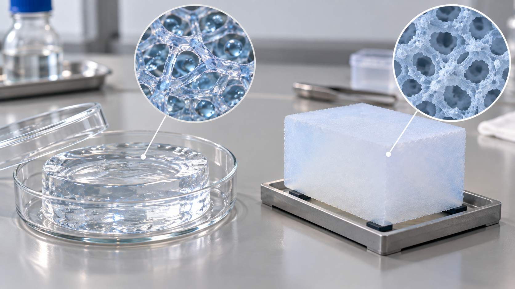
A gel is a material in which a three-dimensional network holds a large amount of liquid. If the liquid is water it is a hydrogel; if the liquid is replaced by gas while the network and pores are kept, the result is an aerogel. With the same kind of “network”, a hydrogel is soft and brittle, and its weak point is strengthened by designs such as double networks. An aerogel is a solid that is more than 90% air, and because its pores are only a few to a few tens of nanometres wide, it suppresses even the heat conduction of air and works as thermal insulation. This article sets out, from primary sources, the structure and toughness design of hydrogels, self-healing gels, ion gels and conductive gels, and the insulation and adsorption of silica, polymer and carbon aerogels. For bio and medical uses it stays with a description of the materials and gives no advice.
- What a gel is (the short version)
- Hydrogels are "soft and brittle" — how toughness is measured and designed
- Self-healing gels, ion gels and conductive gels
- What an aerogel is — how it is dried decides the fate of the network
- Insulation — why it conducts heat worse than air does (our calculation)
- Polymer and carbon aerogels, and adsorption
- On bio and medical uses
- How to read evaluations and standards
- Limits, and what could not be confirmed
- Glossary
- References
- Claim-to-source audit
Sourced = stated in published material (link given)
Our calculation = a figure this article derived, with the assumptions spelled out
Not yet confirmed = a plan or schedule whose record has not been confirmed
Materials-design interpretations are marked separately as Commentary. Inference is shown in bold.
The toughness (fracture energy), thermal conductivity and electrical conductivity figures here are laboratory results reported for particular compositions, sample forms (monolith, blanket, film), water contents, temperatures and measurement methods. The values for gels change greatly with water content and state of drying, and figures from different test methods are not ranked against each other. No individual advice on medical or bio uses is given. Products and companies are not ranked.
1. What a gel is (the short version)
- A composite of a network and a liquid: a gel is a material in which a three-dimensional network (of polymer, silica and so on) holds a liquid. If the liquid is water it is a hydrogel. Sun and co-authors say that hydrogels are used as scaffolds for tissue engineering, vehicles for drug delivery, and actuators for optics and fluidicsSourced[Ref. 4]
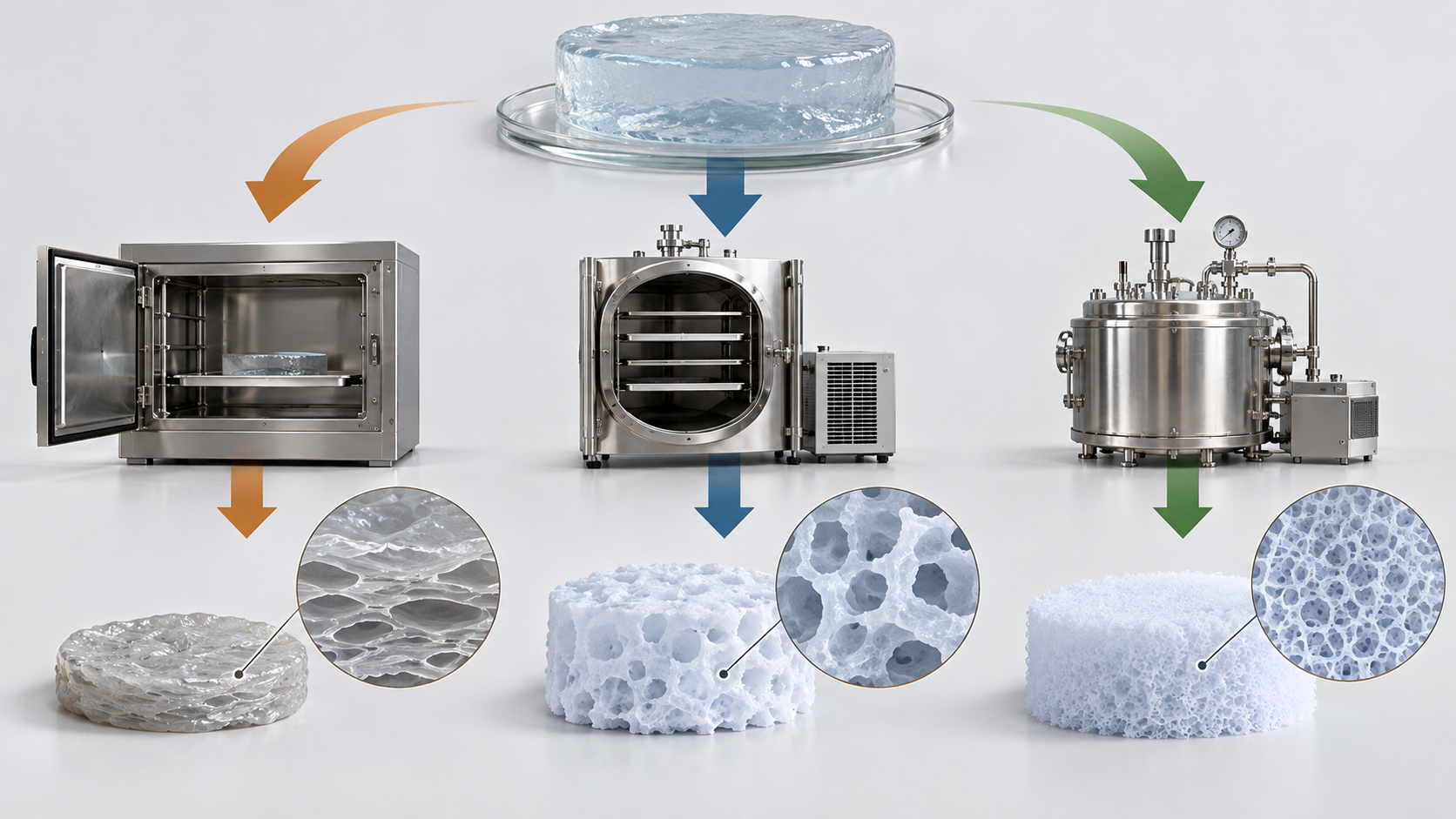
- Dry it into air and you get an aerogel: for a long time an aerogel was defined as a nanostructured material obtained by supercritical drying of a gel made by sol-gel chemistry. Similar materials dried by evaporation were called “xerogels”. With improved subcritical drying, materials with structures very similar to the “classical” supercritically dried aerogels can now be obtained by drying at ambient pressureSourced[Ref. 2].
- The numbers carry conditions: a hydrogel’s values change with water content and test method, an aerogel’s with density, measurement method, temperature and pressure. This article gives the conditions behind each number
The properties of a gel are decided by two things: the design of the network, and how the solvent is removed (or kept). A hydrogel stays wet, so its brittleness is made up for by network design (a second mechanism that dissipates energy). An aerogel loses its solvent while the network tends to shrink under capillary force, so supercritical drying and chemical modification of the surface (silylation) are used to protect the networkSourced[Refs. 2, 4, 5].
2. Hydrogels are “soft and brittle” — how toughness is measured and designed
Calvert says that synthetic hydrogels are in general very weak and so have never been considered alongside polymers and composites as materials for mechanical design, whereas biological gel composites such as cartilage are strong and function as tough, shock-absorbing structural solidsSourced[Ref. 3]. Sun and co-authors note that most hydrogels are brittle, with fracture energies of about 10 J/m², compared with about 1,000 J/m² for cartilage and about 10,000 J/m² for natural rubber. For example, an alginate hydrogel ruptures when stretched to about 1.2 times its original length. Some synthetic elastic hydrogels reach stretches of 10–20, they add, but these values fall markedly in samples containing notchesSourced[Ref. 4].
Strengthening design 1: the double network (Gong and co-authors)
A double-network (DN) gel consists of two networks of opposite character. The first network is an abundantly cross-linked polyelectrolyte (a rigid skeleton) and the second network a poorly cross-linked neutral polymer (a ductile component), synthesized in that order. Gong summarizes that DN gels made under suitable conditions, with about 90 wt% water, have an elastic modulus of 0.1–1.0 MPa, a tensile failure stress of 1–10 MPa (strain 1,000–2,000%), a compressive failure stress of 20–60 MPa (strain 90–95%) and a tearing fracture energy of 100–1,000 J/m². The toughening is based on a local yielding mechanism, with features in common with nanocomposites such as bone and dentinSourced[Ref. 5]. The first report in 2003 showed hydrogels with fracture strengths of some tens of MPa [Ref. 6].
Strengthening design 2: covalent and ionic networks (Sun and co-authors)
Sun and co-authors reported hydrogels of polymers forming ionically and covalently cross-linked networks. Although they contain about 90% water, they can be stretched beyond 20 times their initial length, have a fracture energy of about 9,000 J/m², and show a stretch of 17 even with a notch. The toughness is attributed to the synergy of crack bridging by the covalent network and hysteresis (energy dissipation) by unzipping the ionic network. Because the covalent network preserves the memory of the initial state, much of the large deformation is removed on unloading, and the internal damage from unzipped ionic crosslinks heals by re-zippingSourced[Ref. 4]. The review by Zhao says that tough hydrogels generally combine mechanisms that dissipate large amounts of energy with mechanisms that keep high elasticity, and that implementing such mechanisms across multiple length scales, from nano to macro, is a promising design strategySourced[Ref. 7].
The ratio of the “ordinary hydrogel: about 10 J/m²” of Sun and co-authors to their gel’s “about 9,000 J/m²” is 9,000 ÷ 10 = about 900Our calculation. Against cartilage (about 1,000 J/m²) it is about 9 times, and against natural rubber (about 10,000 J/m²) about 0.9 times. The tearing energy of DN gels, 100–1,000 J/m², is about 10–100 times that of ordinary gels. Assumptions and limits: fracture energy changes with the test (presence of a notch, pulling speed, specimen shape), so comparing values from different papers on one yardstick is only a guide. They share a water content of about 90%, but the compositions and measurement methods are those of separate reports.
In both DN gels and the ionic-covalent gels, there is a two-stage arrangement in which weak bonds that break first (the first network, the ionic crosslinks) absorb energy while the remaining strong network keeps the shape [Refs. 4, 5, 7]. The thinking resembles toughening of metals and ceramics (ductile phases, phase transformation, crack bridging) (this article’s commentary). From the materials side, in a gel of about 90% water the polymer is only about a tenth of the volume, so the heart of the design is an allocation that reconciles energy dissipation and elasticity with little solid. Whether the bonds broken in dissipating energy come back (the “re-zipping” of ionic crosslinks in Sun and co-authors’ gel) decides whether the material can be used repeatedly [Ref. 4].
3. Self-healing gels, ion gels and conductive gels
Self-healing gels
The review by Taylor and in het Panhuis says that self-healing hydrogels generally either are mechanically robust or heal rapidly, but not both, and that a robust hydrogel that heals autonomously on a time scale of seconds has yet to be fully realized. It presents methods to test self-healing efficiency and recovery, mechanisms of autonomous healing and mechanically robust hydrogels, and finds a trend that gels that self-heal better also self-heal fasterSourced[Ref. 8]. Self-healing materials in general (including vitrimers) are covered in this series’ explainer on self-healing materials and vitrimers.
Ion gels
An ion gel is a gel that holds an ionic liquid in a polymer network. Susan and co-authors polymerized methyl methacrylate (MMA) in situ by free-radical polymerization in the ionic liquid EMITFSI (1-ethyl-3-methylimidazolium bis(trifluoromethanesulfonyl)imide) with a small amount of cross-linker, and obtained self-standing, flexible and transparent films. The glass transition temperature fell as the mole fraction of EMITFSI increased, and the ionic conductivity at ambient temperature reached a value close to 10−2 S/cmSourced[Ref. 9]. Lodge says that combining ionic liquids with block polymers makes a virtually unlimited range of composite materials possible [Ref. 10].
Area-specific resistance = thickness ÷ conductivityOur calculation. Applying a conductivity of 10−2 S/cm to a film 100 µm (0.01 cm) thick gives 0.01 ÷ 0.01 = 1 Ω·cm². Assumptions and limits: Susan and co-authors’ value is for one composition (PMMA/EMITFSI) at room temperature, and interfacial resistance with electrodes, film uniformity, temperature and moisture are not included. “1 Ω·cm²” is a guide to magnitude, not a design value for a battery or device.
Conductive gels
Yuk and co-authors developed a 3D-printable conducting-polymer ink based on PEDOT:PSS, and reported that after printing fine structures they could be converted into soft hydrogel microstructures of high conductivity. They say that a soft neural probe could perform in vivo single-unit recordingSourced[Ref. 11]. Only the material is introduced here, and no medical advice is given. Conducting polymers and ion conductors in general are covered in this series’ explainer on conducting polymers and ion conductors.
The conductivity of gels divides into three: ions in water (a water-containing gel with salt dissolved), ions of an ionic liquid (ion gels) and electrons of a conjugated polymer (PEDOT:PSS) (this article’s explanation). Susan and co-authors’ value (about 10−2 S/cm) is ionic conduction from the ionic liquid [Ref. 9], and the PEDOT:PSS of Yuk and co-authors is a mixed electronic (and ionic) conductor [Ref. 11]. A water-containing gel changes in conductivity and mechanical properties when it dries, so an environment that keeps the water content (sealing, humidity) is part of its performance. An ion gel uses an ionic liquid of low vapour pressure and so is hard to dry, which is a design advantage (Inference; primary information on this was not checked in this article), while the trade-off between film mechanical strength and ionic conductivity can be read from Susan and co-authors’ results (Tg changes with composition) [Ref. 9].
4. What an aerogel is — how it is dried decides the fate of the network
Kistler’s “Coherent Expanded Aerogels and Jellies”, published in Nature in 1931, is regarded as the starting point of aerogels [Ref. 1]. According to the review by Koebel and co-authors, when the solvent in the pores of a gel is removed by evaporation, stresses from capillary force shrink the network and cause cracking and warping. Supercritical drying avoids this capillary force and is the royal way to obtain large monolithic aerogelsSourced[Ref. 2].
View the original SVG schematic and exact annotations
Koebel and co-authors describe SiO2 aerogels for insulation as low-density nanostructured solids, with a density of about 0.08–0.2 g/cm³, a porosity above 90% and mesopores about 4–20 nm in diameter. Commercial products are almost all silica-based; the first were made by the Monsanto Chemical Corp. after 1940 following a recipe similar to Kistler’s, production then stopped and later started again. Today’s main products are granular or blanket types (forms composited with fibres and the like)Sourced[Ref. 2].
Porosity = 1 − apparent density ÷ skeletal (silica) densityOur calculation. Assuming a density of amorphous silica of about 2.2 g/cm³, an apparent density of 0.08 g/cm³ gives about 96%, 0.13 g/cm³ about 94%, and 0.2 g/cm³ about 91%. This does not contradict Koebel and co-authors’ “porosity above 90%”. Assumptions and limits: the skeletal density of 2.2 g/cm³ is an assumption as a typical value; the real skeleton contains hydroxyl or organic groups and has a different density. The definition of porosity (open pores only, or all) also changes with the measurement method.
5. Insulation — why it conducts heat worse than air does (our calculation)
In a porous material there are five contributions to heat transfer: (1) conduction through the solid skeleton, (2) conduction through the fluid in the pores (air, water), (3) convection of the pore fluid, (4) radiation from solid surfaces through the pore fluid, and (5) radiation through the solid network or bulk. In an aerogel the pores are so small that the gas conduction (2) is much lower than for a free gas. The heat conduction of the air in the pores falls, following Knudsen’s formula, under the condition that the mean free path of the gas molecules is limited by the pore walls. The low density also thins the skeleton path (1)Sourced[Ref. 2].
The mean free path of air molecules at normal temperature and pressure can be estimated as λ = kBT/(√2 π d² p)Our calculation. With T = 298 K, p = 101,325 Pa and a molecular diameter d assumed to be about 0.37 nm, λ = about 67 nm. The ratio of this to the pores of a silica aerogel (about 4–20 nm), the Knudsen number Kn = λ/pore size, is about 3.3 for 20 nm pores and about 17 for 4 nm. When Kn is well above 1, gas molecules collide with the pore walls more often than with each other, and the gas conduction is smaller than for a free gas. By contrast, the pores of polymer foams such as extruded polystyrene, with which Koebel and co-authors compare, are tens to hundreds of µm, orders of magnitude larger than λ, so gas conduction is about that of free air [Ref. 2]. Assumptions and limits: the molecular diameter is an assumed typical value, and real air is a mixture. This shows “what happens when the pores are smaller than λ” as a guide and does not predict the value of gas conduction.
In specific examples given by Koebel and co-authors, a supercritically dried silica aerogel monolith of density 0.13 g/cm³ had an effective thermal conductivity of 0.015 W/(m·K) measured by the hot-wire method at room temperature, and an ambient-dried silica aerogel blanket (density 0.1 g/cm³) had 0.014 W/(m·K) by the guarded hot plate method under ambient conditions. For a large 1.5 cm thick plate that kept transparency, about 17 mW/(m·K) and a transmittance of about 90% are reported under ambient conditions. For comparison, the thermal conductivity of conventional insulation is about 0.030–0.040 W/(m·K); the boundary for “superinsulation” is commonly 0.025 W/(m·K) and Koebel and co-authors propose 0.020 W/(m·K). For vacuum insulation panels, the equivalent conductivity allowing for 30 years of ageing is noted as about 0.007–0.012 W/(m·K)Sourced[Ref. 2].
Koebel and co-authors state that commercial silica aerogels for insulation have densities of 80–200 kg/m³, and that thermal conductivity is dominated by conduction through the network of solid silica particles at high density and by conduction and radiation through the air in the pores at low density, so an optimum between the two contributions has to be found to obtain the lowest values [Ref. 2]. So it is not the case that the lighter the density, the better the insulation. Also, in high-temperature uses the radiative contribution tends to grow, so values measured over the temperature range of use have to be checked (this article’s commentary; temperature-dependent values were not checked in this article). From the materials side, adding something that scatters or absorbs radiation is a possible answer to this trade-off (Inference; primary information on this was not checked in this article).
6. Polymer and carbon aerogels, and adsorption
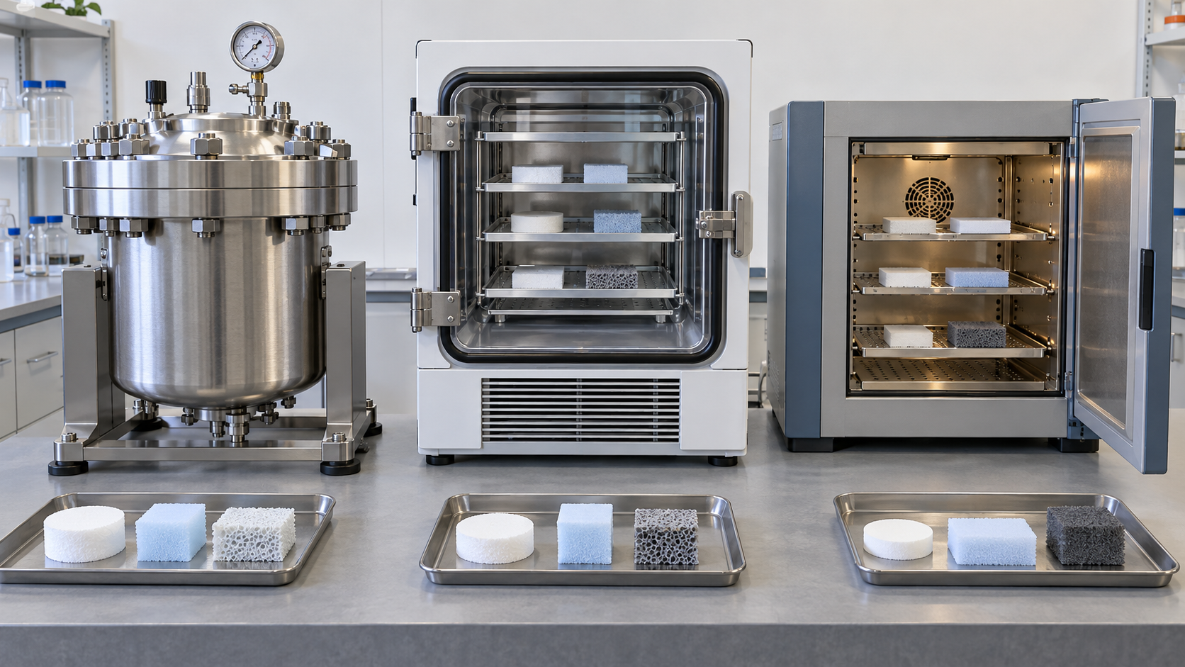
Aerogels are not only silica. Inorganic silica is brittle and sheds dust (Koebel and co-authors say that silica aerogels, though elastic, have inherent mechanical limitations), so organic and carbon skeletons are being studied [Ref. 2].
| Skeleton | Reports confirmed | Note when reading |
|---|---|---|
| Silica | Almost all commercial insulation aerogels. A method that reacts the silanols on the inner pore surfaces of the silica network with isocyanates or amines to coat the fragile skeleton with an organic layer has been adapted for aerospace insulation. Untreated silica aerogel is hydrophilic because of residual silanols and becomes hydrophobic by silylation [2] | Insulation values are in Chapter 5 |
| Polyimide | Meador and co-authors say polyimide aerogels combine high porosity, low thermal conductivity, flexibility, low density and excellent mechanical properties, and reported amine-capped oligomers cross-linked with the cheaper BTC. At the same density, they gave the same or higher modulus and a higher surface area than aerogels cross-linked with the earlier TAB or OAPS. The onset of decomposition depends mainly on the backbone chemistry, with ODA more thermally stable than DMBZ [12] | The authors’ report. The numbers (modulus, surface area) were not checked in the full text |
| Carbon (carbonized organic aerogels) | Biener and co-authors summarize that monolithic resorcinol-formaldehyde-based carbon aerogels have a high mass-specific surface area and electrical conductivity, and discuss applications including hydrogen and electrical energy storage, desalination and catalysis [13] | A statement in a review. Performance values were not checked here |
| Carbon nanotubes + graphene | Sun and co-authors assembled commercial carbon nanotubes and chemically converted graphene sheets into all-carbon aerogels of up to 1,000 cm3, with a density down to 0.16 mg/cm3 and super-elasticity that is invariant from −190 to 900 °C [14] | The density is the apparent density of the skeleton, not a bulk value including air; performance in use (insulation, adsorption) must be confirmed separately |
All Sourced (sources in each cell). The skeletons are not ranked against each other.
0.16 mg/cm³ = 0.16 kg/m³Our calculation. Assuming the density of air at normal temperature and pressure to be about 1.2 kg/m³, the ratio is 0.16 ÷ 1.2 = about 0.13; that is, the mass of the skeleton has a density about 13% of that of air. Assumptions and limits: the density of air is an assumed typical value and changes with temperature and humidity. This is the apparent density of the skeleton without the air in the pores.
Adsorption and the evaluation of pores
For an aerogel used for adsorption, the specific surface area and the pore-size distribution decide performance. Adsorbing nitrogen or argon at 77 K or 87 K can assess pore widths of about 0.45–50 nm, and CO2 adsorption (273–293 K) can be used for the micropores of carbon materials (as stated in the scope of ISO 15901-2)Sourced[Ref. 16]. The determination of specific surface area by the BET method is specified in ISO 9277 [Ref. 15].
The network of an aerogel shrinks easily under capillary force during drying (Chapter 4), so pretreatment before adsorption measurement (degassing temperature and time) may change the pores (Inference; the conditions of individual measurements were not checked in this article). Also, a hydrophilic silica aerogel takes up moisture readily, so thermal conductivity and surface area can both change with the moisture at the time of measurement; always attach whether it was hydrophobized and the storage and pretreatment conditions to the number (this article’s commentary).
7. On bio and medical uses
Sun and co-authors state that hydrogels are used as scaffolds for tissue engineering, vehicles for drug delivery, actuators for optics and fluidics, and model extracellular matrices for biological studiesSourced[Ref. 4]. This article stays with the structure and mechanics of the material and gives no advice on individual medical or bio uses. Hydrogels for cell-culture scaffolds, bioinks and sensors are covered in this series’ explainer on hydrogels (iPS cells and regenerative medicine / biosensors fields).
As examples of standards touching medical uses, ISO 18369-4:2017 specifies test methods for the physicochemical properties of contact lens materials (extraction, rigid lens flexure and breakage, oxygen permeability, refractive index and water content)Sourced[Ref. 20]. ASTM F2900 is a “guide for the characterization of hydrogels used in regenerative medicine”, cited in papers as the basis for tensile specimen geometry and rheological testingSourced[Ref. 25]. Both are standards or guides limited to a use and do not guarantee the performance of hydrogels in general.
8. How to read evaluations and standards
The performance of hydrogels is evaluated by water content (degree of swelling), elastic modulus, fracture strength and fracture energy, and ionic conductivity, and that of aerogels by thermal conductivity, density, porosity, specific surface area and pore-size distribution. Thermal conductivity is measured by steady-state methods (guarded hot plate, heat flow meter), the hot-wire method or the hot-disc method, and specific surface area and pores by gas adsorption. However, an international standard or JIS for measuring the mechanics, water content or ionic conductivity of gels could not be confirmed. For aerogels, standards for the thermal conductivity of insulation and for gas adsorption on powders form the foundation.
| Item evaluated | ISO | IEC / IEEE | JIS | ASTM | What changes the value with test conditions |
|---|---|---|---|---|---|
| Thermal conductivity and thermal resistance (as insulation) | ISO 8301:1991, thermal insulation, determination of steady-state thermal resistance and related properties, heat flow meter apparatus [17]. ISO 8302:1991, guarded hot plate apparatus [18] (both for flat slab specimens). ISO 22007-2:2022, plastics, determination of thermal conductivity and thermal diffusivity, Part 2: transient plane heat source (hot disc) method [19] | Could not be confirmed | JIS A 1412-1, measurement of thermal resistance and thermal conductivity of thermal insulations, Part 1: guarded hot plate method (GHP) (enacted 1999, revised 2016, confirmed 2021) [23]. JIS A 1412-2, Part 2: heat flow meter method (HFM) (enacted 1999, confirmed 2021) [24] | A standard number for aerogel insulation could not be confirmed | Temperature, pressure (vacuum or not), moisture, thickness, sample form (monolith or blanket). In Koebel et al.’s examples the monolith was measured by the hot-wire method and the blanket by guarded hot plate [2] |
| Specific surface area (BET) | ISO 9277:2022, determination of the specific surface area of solids by gas adsorption, BET method [15] | Could not be confirmed | JIS Z 8830, determination of the specific surface area of powders (solids) by gas adsorption (enacted 1990, revised March 2026) [21] | Could not be confirmed | Degassing conditions, adsorbate gas, relative-pressure range, dryness of the sample |
| Pore-size distribution and porosity | ISO 15901-2:2022, pore size distribution and porosity of solid materials by mercury porosimetry and gas adsorption, Part 2: analysis of nanopores by gas adsorption (nitrogen and argon at 77 K and 87 K, about 0.45–50 nm) [16] | Could not be confirmed | JIS Z 8831, pore size distribution and pore characteristics of powders (solids), measurement of nanopores by gas adsorption (enacted 2024) [22] | Could not be confirmed | Adsorbate gas and temperature, pore-shape model, range of pore sizes (larger pores need another method) |
| Water content and mechanics of hydrogels | ISO 18369-4:2017 (physicochemical properties of contact lens materials, including a water-content test; limited to that use) [20]. A standard for hydrogels in general could not be confirmed | Could not be confirmed | Could not be confirmed | ASTM F2900: a guide for the characterization of hydrogels used in regenerative medicine (number and title only; cited in papers) [25] | Water content (changes on drying), specimen shape and pulling speed, relaxation time, temperature, ionic strength |
| Conductivity of ion gels and conductive gels | Could not be confirmed | Could not be confirmed | Could not be confirmed | Could not be confirmed | Interface with electrodes, temperature, moisture, measurement frequency |
Numbers, titles and editions were confirmed on the official page of each body Sourced. For ASTM, only the number and title are given, only where confirmed from non-ASTM material (the reference list of a paper). The arrangement of this table is Our calculation (this article’s rearrangement).
Notes on reading standards
- Insulation standards assume “flat solid slabs”. ISO 8301 and 8302 cover flat slab specimens, and granular material, insulation used in vacuum, or wet gel does not fit them as such. Monoliths, blankets and granules differ in how they are measured and how the sample is prepared, so always look at which form the value is for
- Read a manufacturer’s stated thermal conductivity together with method, temperature, pressure and edition. The values confirmed in this article are laboratory reports, not datasheet values of commercial products. When using a product’s value, check the conditions in the latest datasheet
- The values of gels change greatly with water content. Tensile, compressive and conductivity values cannot be compared unless water content or the equilibrium state is given. ISO 18369-4 and ASTM F2900 are limited to a use (Chapter 7)
9. Limits, and what could not be confirmed
(1) Standard texts
The texts of ISO 8301 and 8302, ISO 22007-2, ISO 9277, ISO 15901-2, ISO 18369-4 and the JIS standards were not checked. Test conditions, procedures and acceptance criteria are not stated. The ASTM website was not opened, and ASTM F2900 is only the number and title confirmed in the reference lists of papers. An ASTM standard for aerogel insulation could not be confirmed as to its number, so none is stated.
(2) Performance of products
The thermal conductivities in datasheets of aerogel insulation products were not checked (numerical values could not be found on company sites). The values in Chapter 5 are those of laboratory samples given in the review by Koebel and co-authors.
(3) Performance as adsorbents, and in drugs and living bodies
The adsorption capacity of aerogels and the behaviour and safety of hydrogels in living bodies were not confirmed in primary sources, so no figures or advice are given. Safety of dust and handling, and regulation (REACH, occupational safety and so on), were not checked either.
(4) Conductivity of conductive gels
The specific conductivity of Yuk and co-authors’ PEDOT:PSS gels has no figure in the abstract and was not confirmed here.
(5) Dependence on time and temperature
The temperature dependence of the thermal conductivity of aerogels (the radiative contribution at high temperature) and the long-term stability of hydrogels (drying, swelling, degradation) were not confirmed in primary sources and are not stated.
- The properties of gels are decided by the design of the network and the handling of the solvent. Hydrogels suppress brittleness by network design, and aerogels suppress brittleness and shrinkage by how they are driedSourced
- Hydrogels are brittle. The fracture energy of an ordinary one is about 10 J/m², while 100–9,000 J/m² has been reported with double networks and dual ionic-covalent networks. The test methods of the reports differSourced / Our calculation
- Aerogel insulation owes much to the smallness of the pores. The pores (4–20 nm) are smaller than the mean free path of air molecules (about 67 nm), with Kn about 3–17; 0.014–0.017 W/(m·K) has been reported in laboratoriesOur calculation / Sourced
- Skeletons are not only silica. Polyimide, carbon and graphene skeletons have been reportedSourced
- The foundations of evaluation are standards for insulation and gas adsorption; standards for the mechanics and conductivity of gels could not be confirmed. Read numbers together with water content, form and temperature
10. Glossary
- Gel
- A material in which a three-dimensional network holds a liquid.
- Hydrogel
- A gel whose liquid is water.
- Double-network (DN) gel
- A gel layering a rigid, heavily cross-linked network and a ductile, lightly cross-linked one.
- Fracture energy
- The energy needed for a crack to advance per unit area (J/m²). An index of toughness.
- Ion gel
- A gel that holds an ionic liquid in a polymer network.
- Aerogel
- A porous solid in which the solvent of a gel is replaced by gas while the network and pores are kept.
- Xerogel
- A shrunken dry gel obtained by evaporative drying.
- Supercritical drying
- Removing the solvent in its supercritical state, avoiding capillary force.
- Silylation
- Replacing surface silanol groups with alkyl and similar groups. Used for hydrophobization.
- Knudsen number
- The mean free path of gas molecules divided by the pore size.
- BET method
- A method of finding specific surface area from gas adsorption.
- Mesopore
- A pore about 2–50 nm wide.
11. References
- Kistler S. S. “Coherent Expanded Aerogels and Jellies”, Nature 127, 741 (1931), DOI 10.1038/127741a0 (bibliographic record only) — doi.org/10.1038/127741a0
- Koebel M., Rigacci A., Achard P. “Aerogel-based thermal superinsulation: an overview”, J. Sol-Gel Sci. Technol. 63, 315–339 (2012), DOI 10.1007/s10971-012-2792-9 (public version at Empa checked) — dora.lib4ri.ch (Empa)
- Calvert P. “Hydrogels for Soft Machines”, Adv. Mater. 21, 743–756 (2009), DOI 10.1002/adma.200800534 — doi.org/10.1002/adma.200800534
- Sun J.-Y. et al. “Highly stretchable and tough hydrogels”, Nature 489, 133–136 (2012), DOI 10.1038/nature11409 — doi.org/10.1038/nature11409
- Gong J. P. “Why are double network hydrogels so tough?”, Soft Matter 6, 2583 (2010), DOI 10.1039/B924290B — doi.org/10.1039/b924290b
- Gong J. P. et al. “Double-Network Hydrogels with Extremely High Mechanical Strength”, Adv. Mater. 15, 1155–1158 (2003), DOI 10.1002/adma.200304907 — doi.org/10.1002/adma.200304907
- Zhao X. “Multi-scale multi-mechanism design of tough hydrogels: building dissipation into stretchy networks”, Soft Matter 10, 672–687 (2014), DOI 10.1039/c3sm52272e (open access) — doi.org/10.1039/c3sm52272e
- Taylor D. L., in het Panhuis M. “Self-Healing Hydrogels”, Adv. Mater. 28, 9060–9093 (2016), DOI 10.1002/adma.201601613 — doi.org/10.1002/adma.201601613
- Susan M. A. B. H. et al. “Ion Gels Prepared by in Situ Radical Polymerization of Vinyl Monomers in an Ionic Liquid and Their Characterization as Polymer Electrolytes”, J. Am. Chem. Soc. 127, 4976–4983 (2005), DOI 10.1021/ja045155b — doi.org/10.1021/ja045155b
- Lodge T. P. “A Unique Platform for Materials Design”, Science 321, 50–51 (2008), DOI 10.1126/science.1159652 — doi.org/10.1126/science.1159652
- Yuk H. et al. “3D printing of conducting polymers”, Nat. Commun. 11, 1604 (2020), DOI 10.1038/s41467-020-15316-7 (open access) — doi.org/10.1038/s41467-020-15316-7
- Meador M. A. B. et al. “Polyimide Aerogels with Amide Cross-Links: A Low Cost Alternative for Mechanically Strong Polymer Aerogels”, ACS Appl. Mater. Interfaces 7, 1240–1249 (2015), DOI 10.1021/am507268c — doi.org/10.1021/am507268c
- Biener J. et al. “Advanced carbon aerogels for energy applications”, Energy Environ. Sci. 4, 656 (2011), DOI 10.1039/C0EE00627K — doi.org/10.1039/c0ee00627k
- Sun H., Xu Z., Gao C. “Multifunctional, Ultra-Flyweight, Synergistically Assembled Carbon Aerogels”, Adv. Mater. 25, 2554–2560 (2013), DOI 10.1002/adma.201204576 — doi.org/10.1002/adma.201204576
- ISO “ISO 9277:2022” (Edition 3, November 2022) — iso.org/standard/71014.html
- ISO “ISO 15901-2:2022” (Edition 2, January 2022) — iso.org/standard/67586.html
- ISO “ISO 8301:1991” (Edition 1, reconfirmed in 2025) — iso.org/standard/15421.html
- ISO “ISO 8302:1991” (Edition 1, reconfirmed in 2024) — iso.org/standard/15422.html
- ISO “ISO 22007-2:2022” (Edition 3, June 2022) — iso.org/standard/81836.html
- ISO “ISO 18369-4:2017” (Edition 2, August 2017, reconfirmed in 2023) — iso.org/standard/66341.html
- Japanese Industrial Standards Committee (JISC) “JIS Z 8830” search result and detail page (enacted 1 July 1990, last revised 23 March 2026) — jisc.go.jp (JIS Z 8830)
- Japanese Industrial Standards Committee (JISC) “JIS Z 8831” search result and detail page (enacted 21 March 2024) — jisc.go.jp (JIS Z 8831)
- Japanese Industrial Standards Committee (JISC) “JIS A 1412-1” search result and detail page (enacted 20 April 1999, last revised 22 August 2016, last confirmed 20 October 2021) — jisc.go.jp (JIS A 1412-1)
- Japanese Industrial Standards Committee (JISC) “JIS A 1412-2” search result and detail page (enacted 20 April 1999, last confirmed 20 October 2021) — jisc.go.jp (JIS A 1412-2)
- Baniasadi M., Minary-Jolandan M. “Alginate-Collagen Fibril Composite Hydrogel”, Materials 8, 799 (2015), DOI 10.3390/ma8020799 (open access; its reference list includes ASTM F2900-11 “Standard Guide for Characterization of Hydrogels used in Regenerative Medicine”) — pmc.ncbi.nlm.nih.gov/articles/PMC5455273
12. Claim-to-source audit
| Claim in the text | Basis | Class |
|---|---|---|
| That the paper regarded as the starting point of aerogels exists (Kistler 1931, bibliographic record only) | Crossref bibliographic record Reference 1 https://doi.org/10.1038/127741a0 | Sourced |
| The definition of aerogels (supercritical drying) and xerogels, progress in ambient-pressure drying, shrinkage by capillary force, supercritical drying as the way to monoliths, commercial products being granular or blanket, silica density 0.08–0.2 g/cm³, porosity above 90% and mesopores 4–20 nm, the Monsanto history, the five contributions to heat transfer, Knudsen, the optimum density, the monolith at 0.015 W/(m·K) (0.13 g/cm³, hot wire), the blanket at 0.014 W/(m·K) (0.1 g/cm³, guarded hot plate), the transparent plate at about 17 mW/(m·K) and about 90% transmittance, conventional insulation at 0.030–0.040, the superinsulation boundaries of 0.025 and 0.020, vacuum panels at 0.007–0.012 after 30 years, reinforcement of silica, hydrophilicity and silylation with spring-back, and the pore sizes of polymer foams such as extruded polystyrene | Review by Koebel et al. (2012) Reference 2 https://www.dora.lib4ri.ch/empa/dload/empa:5435/PDF/view | Sourced |
| That synthetic hydrogels are in general weak while biological gel composites are strong | Abstract of Calvert (2009) Reference 3 https://doi.org/10.1002/adma.200800534 | Sourced |
| Uses of hydrogels, their brittleness (fracture energy about 10 J/m², cartilage about 1,000, natural rubber about 10,000, alginate rupturing at about 1.2 times, some synthetic gels at 100–1,000), and the ionic-covalent gel (about 90% water, stretching beyond 20 times, about 9,000 J/m², a stretch of 17 with a notch, the mechanisms, re-zipping) | Sun et al. (Nature 2012) Reference 4 https://doi.org/10.1038/nature11409 | Sourced |
| The composition of DN gels (rigid first network, ductile second network), about 90 wt% water, modulus 0.1–1.0 MPa, tensile 1–10 MPa (strain 1,000–2,000%), compressive 20–60 MPa (strain 90–95%), tearing 100–1,000 J/m², and the local yielding mechanism | Abstract of Gong (Soft Matter 2010) Reference 5 https://doi.org/10.1039/b924290b | Sourced |
| The first report of DN gels (fracture strengths of some tens of MPa) | Abstract of Gong et al. (Adv. Mater. 2003) Reference 6 https://doi.org/10.1002/adma.200304907 | Sourced |
| That tough hydrogels have both energy-dissipating and elasticity-keeping mechanisms, and the strategy of implementing them across several length scales | Abstract of Zhao (Soft Matter 2014) Reference 7 https://doi.org/10.1039/c3sm52272e | Sourced |
| That self-healing hydrogels struggle to be both robust and quickly healing, and the trend that gels that heal better heal faster | Abstract of Taylor and in het Panhuis (Adv. Mater. 2016) Reference 8 https://doi.org/10.1002/adma.201601613 | Sourced |
| Ion gels (MMA polymerized in situ in EMITFSI, self-standing, flexible, transparent, a fall in Tg, ionic conductivity at room temperature close to 10−2 S/cm) | Abstract of Susan et al. (JACS 2005) Reference 9 https://doi.org/10.1021/ja045155b | Sourced |
| That combining ionic liquids with block polymers widens the range of composite materials | Abstract of Lodge (Science 2008) Reference 10 https://doi.org/10.1126/science.1159652 | Sourced |
| The 3D-printing ink of PEDOT:PSS, conversion to conductive soft hydrogel microstructures, and the prototype neural probe | Abstract of Yuk et al. (Nat. Commun. 2020) Reference 11 https://doi.org/10.1038/s41467-020-15316-7 | Sourced |
| Properties of polyimide aerogels, crosslinking with BTC, modulus and surface area, and the backbone dependence of the onset of decomposition | Abstract of Meador et al. (2015) Reference 12 https://doi.org/10.1021/am507268c | Sourced |
| Features of carbon aerogels (surface area, electrical conductivity) and applications (hydrogen and electrical energy storage, desalination, catalysis) | Abstract of Biener et al. (EES 2011) Reference 13 https://doi.org/10.1039/c0ee00627k | Sourced |
| All-carbon aerogels of CNTs and graphene (up to 1,000 cm3, down to 0.16 mg/cm3, super-elasticity from −190 to 900 °C) | Abstract of Sun et al. (Adv. Mater. 2013) Reference 14 https://doi.org/10.1002/adma.201204576 | Sourced |
| Numbers, titles, editions and scope of ISO 9277:2022, ISO 15901-2:2022 (nitrogen and argon at 77 K and 87 K, about 0.45–50 nm, CO2), ISO 8301:1991, ISO 8302:1991, ISO 22007-2:2022 and ISO 18369-4:2017 (including a water-content test) | ISO standard pages Reference 15 https://www.iso.org/standard/71014.html Reference 16 https://www.iso.org/standard/67586.html Reference 17 https://www.iso.org/standard/15421.html Reference 18 https://www.iso.org/standard/15422.html Reference 19 https://www.iso.org/standard/81836.html Reference 20 https://www.iso.org/standard/66341.html | Sourced |
| Numbers, titles, enactment, revision and confirmation dates of JIS Z 8830, Z 8831, A 1412-1 and A 1412-2 | JISC database Reference 21 https://www.jisc.go.jp/app/jis/general/GnrJISNumberNameSearchList?show&jisStdNo=Z8830 Reference 22 https://www.jisc.go.jp/app/jis/general/GnrJISNumberNameSearchList?show&jisStdNo=Z8831 Reference 23 https://www.jisc.go.jp/app/jis/general/GnrJISNumberNameSearchList?show&jisStdNo=A1412-1 Reference 24 https://www.jisc.go.jp/app/jis/general/GnrJISNumberNameSearchList?show&jisStdNo=A1412-2 | Sourced |
| That ASTM F2900-11 “Standard Guide for Characterization of Hydrogels used in Regenerative Medicine” is listed in the reference list of a paper and cited as the basis for tensile specimen geometry and rheology (the ASTM website was not consulted) | Materials 8, 799 (2015) and others (non-ASTM public material) Reference 25 https://pmc.ncbi.nlm.nih.gov/articles/PMC5455273/ | Sourced |
| The ratios of fracture energy (about 900 times; about 9 times against cartilage, about 0.9 times against rubber; about 10–100 times for DN gels), the area resistance of an ion-gel film (1 Ω·cm² at 100 µm), the porosity of silica (about 96%, 94%, 91%), the mean free path of air (about 67 nm) and Knudsen numbers (about 3.3–17), the ratio of 0.16 mg/cm³ to air (about 0.13), and the arrangement of the standards table | Our calculation. Assumptions and limits are stated in each place (skeletal density 2.2 g/cm³, molecular diameter 0.37 nm, air density 1.2 kg/m³ and so on) | Our calculation |
| The texts of standards, general standards for measuring the mechanics, water content and conductivity of gels, an ASTM standard for aerogel insulation, thermal conductivity in product datasheets, adsorption capacity, behaviour and safety in living bodies, dust and regulation, the conductivity of PEDOT:PSS gels, the high-temperature thermal conductivity of aerogels, and the long-term stability of hydrogels | Could not be confirmed in the primary sources accessible within the scope of this survey, so they are not stated | Commentary |
| The readings that “the key to strengthening a hydrogel is designing how it breaks”, “the conductivity of a gel divides three ways by what carries the charge”, “aerogel insulation is a trade-off between an optimum density and radiation”, and “aerogel measurements depend on pretreatment”. The arrangement of drying routes in Fig. 3 | This article’s arrangement and commentary based on published content. Not views stated by any institution or company | Commentary |
| That Figs. 2, 3, 4 and 5 are explanatory drawings, not real observations or data, and that Figs. 1 and 6 are AI-generated images | Note by this article | Commentary |
Last updated 10 October 2026. Sources are limited to primary material (peer-reviewed papers, the review by Koebel and co-authors, and standards-body pages). The texts of standards are paid and could not be checked. The ASTM International website was not consulted. Because the article includes structural readings and materials-design interpretations, those are marked as Commentary and kept separate from sourced fact. The texts of standards, general standards for the mechanics, water content and conductivity of gels, thermal conductivity in product datasheets, adsorption capacity, behaviour and safety in living bodies, regulation, and the high-temperature thermal conductivity of aerogels could not be confirmed and are not stated here. The fracture energy, thermal conductivity and conductivity figures are results for particular samples and test conditions and cannot be generalised to other samples or products. No advice on medical or bio uses is given. All figures are explanatory concept graphics. Figs. 2, 3, 4 and 5 are vector drawings; Figs. 1 and 6 are AI-generated images, and none of them shows a real cross-section, micrograph or physical product.