TECHNOLOGY EXPLAINER
Metamaterials and Metasurfaces
— rewriting a material’s behaviour with the dimensions of its structure, and the distance from laboratory to deployment
A metamaterial is built from structures smaller than the wavelength, arranged so that waves behave in ways the composition alone would not give: electromagnetic phase and absorption, or the blocking of sound. Its two-dimensional, wavelength-thin version is the metasurface. For 6G it appears as the “reflective intelligent surface” (RIS) whose reflection direction can be changed, as a radio-wave lens attached to window glass, and as a lightweight sound-insulation material, with prototypes and demonstrations announced one after another. The obstacles are just as clear: narrow bandwidth, loss, the cost of the tuning elements, and what the technology is compared with in the field (repeaters, for example). This article sets out, from primary sources, the principle, what matters in the materials and structures, representative electromagnetic and acoustic examples, the gap between laboratory and deployment, and how to read the evaluation standards.
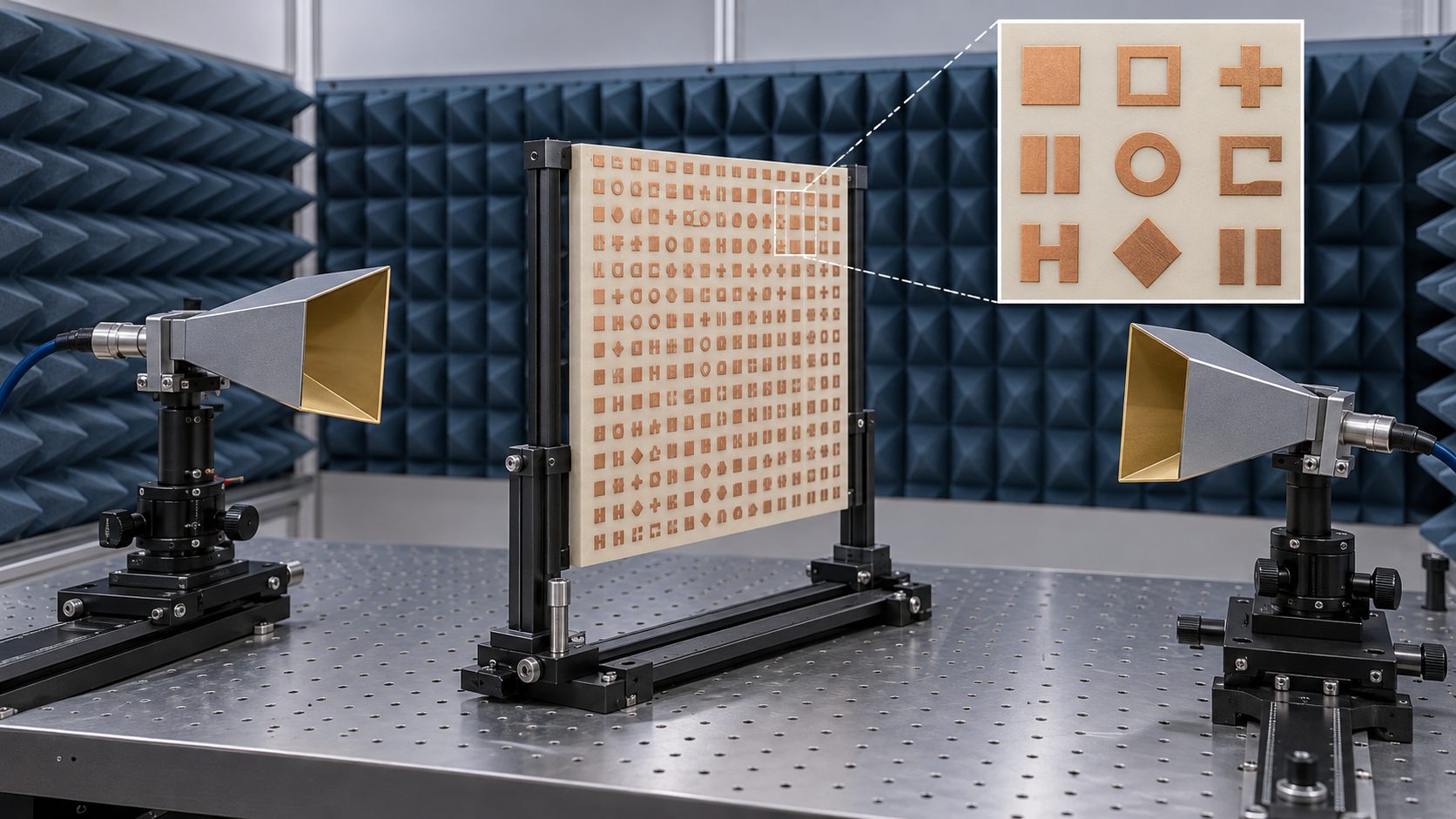
- Metamaterials and metasurfaces (the short version)
- Principle — structures smaller than the wavelength act as an effective medium
- Metasurfaces — setting the phase place by place
- Our calculation: the wavelength at 28 GHz, and the number of elements
- Radio-wave absorbers and stealth — the limits of bandwidth and thickness
- A materials engineer's view 1: loss, and tunable materials
- RIS for 6G and radio-wave lenses for window glass — from laboratory to field
- Acoustic and elastic-wave metamaterials — sound insulation and vibration control
- A materials engineer's view 2: resonances drift
- Laboratory performance versus deployment
- Limits, and what could not be confirmed
- How to read evaluations and standards
- Glossary
- References (primary sources)
- Claim-to-source audit
Sourced = stated in published material (link given)
Our calculation = a figure this article derived, with the assumptions spelled out
Not yet confirmed = a plan, schedule or research-stage matter whose record has not been confirmed
Materials-design interpretations are marked separately as Commentary. Inference is shown in bold.
The absorption, sound-insulation and efficiency figures here are results for particular samples measured at particular frequencies and under particular conditions, in laboratory tests or demonstrations. They do not describe production products or performance in the field. A claim of being “the world’s first” is treated as the claim of the company or institution that made the announcement, not as independent confirmation. This article does not rank products or companies. Optical metalenses are covered in the next article (see our explainer on metalenses and flat optics); here the focus is on radio waves, sound and elastic waves.
1. Metamaterials and metasurfaces (the short version)
- Dimensions, not composition, set the behaviour: when structures much smaller than the wavelength (metal patterns, resonators, cavities, thin films with lattices) are arranged periodically, the whole behaves as one medium whose effective permittivity and permeability (for electromagnetic waves) or effective density and bulk modulus (for sound) can take values the composition alone cannot give. The review by Smith et al. states that artificially constructed metamaterials can show electromagnetic characteristics unlike those of any conventional material, such as artificial magnetism and negative refractive indexSourced [Source 1]
- A metasurface makes a wavefront with a thin sheet: a two-dimensional array whose elements impose different phase delays sets the direction of reflection or refraction. Yu et al. showed that abrupt phase changes over a wavelength-scale distance allow the laws of reflection and refraction to be generalisedSourced [Source 4]
- The difficulty lies on the deployment side: narrow bandwidth, loss in metals and dielectrics, the components that switch the elements, and the field comparison (against existing repeaters) create the distance between a clean laboratory curve and the field. The 2024 roadmap on active metamaterials likewise says that their added complexity makes progress hard, particularly beyond theory and laboratory experimentsSourced [Source 20]
A metamaterial is not a new substance but a structure designed through its dimensions. That is why the design freedom is large, and also why the operating frequency is tied to the structure’s size (which scales with the wavelength), and why material loss and manufacturing scatter show up directly in performance. A number that does not say “at how many GHz, over what bandwidth, with what efficiency” cannot be compared.
2. Principle — structures smaller than the wavelength act as an effective medium
A wave does not “see” the individual details of structures much smaller than its wavelength; it feels them as an averaged medium. Designing this averaged (effective) medium through the shape, size and arrangement of the structure is the idea behind metamaterials. The review by Smith et al. describes metamaterials showing electromagnetic properties that conventional materials lack (artificial magnetism, negative refractive index) and the value of expanding our view of what constitutes a materialSourced [Source 1].
On the theory side, Pendry showed that a slab of negative-refractive-index material can focus all Fourier components of an image, including non-propagating ones (a “superlens”). He stated that this could be realised in the microwave band with then-current technology, and simulated that a thin slab of silver could resolve objects only a few nanometres across at visible frequenciesSourced [Source 2] (the optical side is covered in our explainer on metalenses and flat optics). On the experimental side, Schurig et al. reported in 2006 a microwave-band experiment in which a metamaterial cloak “hid” a copper cylinder, reducing scattering and shadow. They presented it as the first practical realisation of a cloak following a theory that held such a cloak possible, at least over a narrow frequency bandSourced [Source 3].
3. Metasurfaces — setting the phase place by place
Yu et al. showed experimentally that a two-dimensional array imposing abrupt phase changes at the wavelength scale (metallic antennas on silicon) produces anomalous reflection and refraction, in excellent agreement with generalised laws derived from Fermat’s principle. They also showed that such phase discontinuities can generate optical vorticesSourced [Source 4]. Conventional optical components build up phase gradually as the wave propagates; a metasurface instead imposes the phase abruptly on a thin surface, so the thickness can be kept to about a wavelengthSourced [Source 4].
As a way to switch electromagnetic phase electrically, Cui et al. proposed the coding metamaterial, in which two kinds of unit cell with 0 and π phase response are treated as “0” and “1”. With a biased diode switching each cell between 0 and 1, and a field-programmable gate array (FPGA) changing the sequence, a single surface becomes a “programmable metamaterial” that manipulates waves in different ways; they confirmed this by numerical simulation and experimentSourced [Source 5]. Di Renzo et al. sort RIS implementations into large arrays of inexpensive antennas, usually spaced half a wavelength apart, and metamaterial-based surfaces whose scattering elements are much smaller than the wavelength. They state that RISs need the largest number of scattering elements, but each is backed by the fewest and least costly components, and that no power amplifiers are usually neededSourced [Source 9].
4. Our calculation: the wavelength at 28 GHz, and the number of elements
Let us check numerically that dimensions scale with wavelength. Taking the speed of light as 299,792,458 m/s, the wavelength at 28 GHz is about 10.7 mm and at 39 GHz about 7.7 mmOur calculation. If elements are packed at half-wavelength pitch, a 50 cm square holds about 93 elements per side at 28 GHz (about 8,650 elements) and about 130 per side at 39 GHz (about 16,900 elements)Our calculation.
In their announcement of 28 February 2025, Japan Display (JDI), KDDI and KDDI Research presented a portable liquid-crystal metasurface reflector for the 28 GHz band that is about 50 cm square and about 8 kg, switched on and off from a smartphone, with a changeable scattering pattern (manufacturers’ stated values)Sourced [Source 18]. The element pitch, the number of elements and how voltage is applied to the liquid crystal could not be confirmed from this announcement.
5. Radio-wave absorbers and stealth — the limits of bandwidth and thickness
One of the first practical applications of metamaterials is the radio-wave absorber. Landy et al. showed a design in which two resonators, coupling separately to the electric and magnetic fields, are placed in a single unit-cell layer to absorb nearly all incident radiation. The fabricated sample had a predicted absorbance of 96% and a measured peak absorbance above 88% at 11.5 GHz. Because the structure consists solely of metallic elements, the substrate can be chosen for other properties, they noteSourced [Source 6].
An absorption figure always comes with a frequency, an angle of incidence and a polarisation. The Landy value is a measurement at one frequency, 11.5 GHz, and does not demonstrate absorption over a wide bandSourced [Source 6]. There is also a fundamental limit between thickness and bandwidth for an absorber backed by a metal plate. From the analytic properties of the reflection coefficient of a metal-backed multilayer slab, Rozanov derived the lower bound on the thickness-to-bandwidth ratio of a physically realisable radar absorber, and showed that the least thickness of a 10 dB broadband dielectric radar absorber is 1/17 of the largest operating wavelengthSourced [Source 7].
Let us apply the 1/17 to some frequencies (taking the wavelength in vacuum, and reading the “largest operating wavelength” as the wavelength at the lowest frequency at which the absorber operates; that reading is our interpretation and contains an inference). Working from 1 GHz upward gives about 17.6 mm; from 3 GHz, about 5.9 mm; from 10 GHz, about 1.8 mm; and from 28 GHz, about 0.63 mmOur calculation. These numbers show that absorbing broadly down to low frequencies requires either giving up thinness or using another means such as magnetic materials (the bound is for the dielectric case; the abstract indicates that a different relation applies when magnetic materials are used)Sourced [Source 7].
The cloak of Schurig et al. is a laboratory demonstration for a limited microwave band and a simple object, a copper cylinder [Source 3]. Application to the low observability (stealth) of real aircraft or ships, and its performance, cannot be confirmed from published primary sources. This article therefore says nothing about how good stealth performance is or how far it has been put into practice.
6. A materials engineer’s view 1: loss, and tunable materials
A metamaterial structure combines metal patterns, a dielectric substrate and tuning elements (diodes, liquid crystal and so on). Khurgin states that metal losses affect the performance of every plasmonic or metamaterial structure, and that how they are dealt with will determine the degree to which these structures find practical applicationsSourced [Source 8] (the original concerns optical-frequency plasmonics; that metal loss matters equally for microwave and millimetre-wave resonant structures is our inference).
The tuning material: the liquid-crystal metasurface reflector of JDI and KDDI Research applies the liquid crystal used for light control in displays to radio-wave control. A liquid-crystal layer sits between the reflecting elements and the ground plane, the reflecting elements double as electrodes, and the applied voltage changes the permittivitySourced [Source 17]. How much the liquid crystal’s dielectric loss matters at millimetre-wave frequencies could not be confirmed from that announcement. The window-glass material: the NTT DOCOMO and AGC announcement states that the heat-shielding film applied to glass reflects radio waves. For the combination of heat-shielding glass with a metasurface lens, it says AGC’s glass radio-transmission structure design technology was used so that millimetre waves pass without impairing heat shieldingSourced [Source 16].
Commentary: on windows and facades, visible-light transmission, heat shielding, radio-wave transmission and reflection, and weather resistance are required together, so the conductive-film material, film thickness and pattern line width become the design trade-offs directly. Differences among transparent conductive materials are covered in our explainer on transparent conductive films.
Dynamic metasurfaces have traditionally given each element its own control signal. NTT DOCOMO and AGC demonstrated that, by arranging four kinds of elements with different structures appropriately, the focal position can be switched even when every element receives the same control signal (switching between one focus and two), and say that simple control makes it possible to change the focus even of a large-area lensSourced [Source 16]. As the number of elements grows, the control circuitry dominates, so simplifying control through the materials side is important (our commentary).
7. RIS for 6G and radio-wave lenses for window glass — from laboratory to field
Millimetre waves at 28 GHz and above travel in straight lines, so places that radio waves do not reach (coverage holes) arise easily in the shadow of buildings and trees. The motivation for RIS and metasurface reflectors is to deliver the signal into such places by reflecting or focusing it with a surface, instead of adding base stationsSourced [Sources 15, 17]. Di Renzo et al. organise RIS as an enabling technology for smart radio environments (SREs). Compared with phased arrays, multi-antenna transmitters and relays, they say, RISs need many elements but few and cheap components per element and usually no power amplifiers, so they could be built with low cost, size, weight and power (C-SWaP)Sourced [Source 9].
The published experiments and demonstrations (Japanese examples)
| Date | Announcing party | Content (as stated in the announcement) | Conditions to keep in mind |
|---|---|---|---|
| Experiment of 14–18 December 2020 (announced 26 January 2021) | NTT DOCOMO and AGC | A film-shaped metasurface lens for window glass. In the 28 GHz band it gathers millimetre waves passing through window glass at a focal point indoors. Taking float glass alone as 0 dB, the received power at the focus was above 24 dB at 27.6 GHz. Heat-shielding (metal-film) glass was −29 dB, about 0 dB with a radio-transmission structure, and about 24 dB with the metasurface lens added. A dynamic lens switched its focus at 29.5 GHz | Normal-incidence measurement at the DOCOMO R&D Center. A value at the focus, not for the whole surface. A company announcementSourced [16] |
| 7 October 2021 | JDI and KDDI Research | A liquid-crystal metasurface reflector whose reflection direction can be varied (28 GHz band). A small prototype sample was tested in an anechoic chamber; by changing the voltage setting, the reflection direction changed from the direction of receiving antenna #1 to that of #2. The announcement calls it a world first | Small prototype, anechoic chamber. “World first” is the announcers’ claimSourced [17] |
| 12 November 2021 | NTT and NTT DOCOMO | A successful experiment changing the reflection direction dynamically as the user moves. NTT’s reflection-control technology was applied to AGC’s millimetre-wave RIS reflector. Base-station radio waves that entered a room through a window were reflected, improving the received power of a moving receiver over a wide area. Called a world first | An indoor experiment with a moving receiver (details such as location and area are in an annex that we did not check). “World first” is the announcers’ claim. Further study as a leading candidate is statedSourced / Not yet confirmed [15] |
| Demonstration of 21 December 2024 – 31 March 2025 (announced 28 February 2025) | JDI, KDDI and KDDI Research | A portable 28 GHz liquid-crystal reflector (about 50 cm square, about 8 kg, on/off and scattering pattern changed from a smartphone). In the Nishi-Shinjuku district of Shinjuku, Tokyo, commercial millimetre waves were reflected into hard-to-reach places between buildings. Operation from a solar panel and battery was also confirmed | Outdoor real environment. The improvement in dB was not given numerically in the body of this announcement. The statement that the three companies will work toward practical use is Not yet confirmed [18] |
The numbers and the “world first” claims are all those of the announcing companies and institutions. Please do not rank experiments that differ in conditions (measurement point, area, environment).
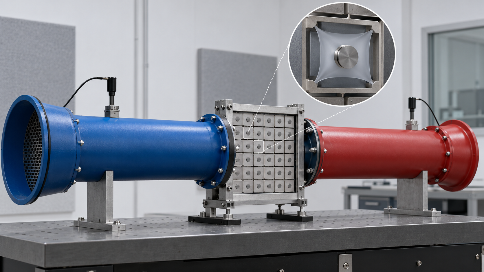
Standardisation, and critical views
On the standards side, ETSI (the European Telecommunications Standards Institute) announced on 25 April 2025 two new reports: “Implementation and Practical Considerations” (GR RIS 004, covering RIS unit-cell design, switching methods, RIS types, the RIS controller, costs, field trials and measurement methods) and “Diversity and Multiplexing of RIS-aided Communications” (GR RIS 005). It also said that it had updated its three earlier reports: GR RIS 001 (Use Cases, Deployment Scenarios and Requirements), 002 (Technological Challenges and Impact on Architecture and Standards) and 003 (Communication Models, Channel Models, Channel Estimation, and Evaluation Methodology)Sourced [Source 13]. These are group reports, not standards themselves.
In 3GPP, the network-controlled repeater (NCR), a repeater with added network control, was studied in Release 18. Technical report TR 38.867 V18.0.0 (September 2022) assumes the NCR to be an in-band RF repeater (a relay that amplifies the received band and re-transmits it) for the FR1 and FR2 bands, single-hop and stationary, and transparent to the UE, and notes that cost efficiency is a key consideration. The study covers side control information (beam, timing, UL-DL TDD configuration, ON-OFF, power control), its signalling, and repeater managementSourced [Source 14]. For RIS, a preprint by Åström et al. states that RIS was proposed as a study item in both 3GPP Releases 18 and 19 but was not continued in either and was left for possible future specification, and it sets out practical issues as the rationale. The same paper compares RIS with the network-controlled repeater standardised in Release 18Sourced (a non-peer-reviewed preprint; we did not check the 3GPP meeting records themselves) [Source 12].
Within research, views are divided. Björnson et al. sorted out misunderstandings that spread amid the rising expectations for RIS, and examined three myths: that current network technology can only control the transmitter and receiver, not the environment in between; that RIS achieves a better asymptotic array gain than conventional beamforming; and that the path loss is the same as with anomalous mirrors. They named two questions that must be answered for RIS to succeed: a convincing use case, and how to estimate channels and control an RIS in real timeSourced [Source 10]. Tang et al. organised the free-space path loss of RIS as a function of the distances to the transmitter and receiver, the RIS size, near-field and far-field effects, and the radiation patterns of antennas and unit cells, and reported that measurements of three fabricated RISs in a microwave anechoic chamber matched the models wellSourced [Source 11]. The difference between an anechoic chamber and a reflective field site is set out in Chapter 10.
8. Acoustic and elastic-wave metamaterials — sound insulation and vibration control
An ordinary wall blocks sound better the heavier it is (the mass law). Keeping weight low while still blocking sound is one motivation for acoustic metamaterials. In 2000, Liu et al. fabricated “locally resonant” sonic crystals and showed spectral gaps, ranges of frequencies where sound does not pass, with a lattice constant two orders of magnitude smaller than the relevant wavelength. The composite behaves as a material with effective negative elastic constants, and a 2 cm slab broke the conventional mass-density law of sound transmission by one or more orders of magnitude at 400 Hz, they reportSourced [Source 19]. Yang et al. built a simple membrane-type metamaterial, a thin film with a small mass attached, divided by a rigid grid, and report breaking the mass-density law by about 200 times in the 100–1000 Hz range. The eigenfrequencies can be tuned by placing a small mass at the centre of the membrane, and near-total reflection occurs at a frequency between two eigenmodes, where the in-plane average of the normal displacement is zeroSourced [Source 21]. The review by Ma and Sheng traces acoustic metamaterials over about 15 years, from an academic curiosity to an active field, from local resonances to phase manipulation, superabsorption, active control, and wave transport in moving fluids, elastic and mechanical metamaterialsSourced [Source 23].
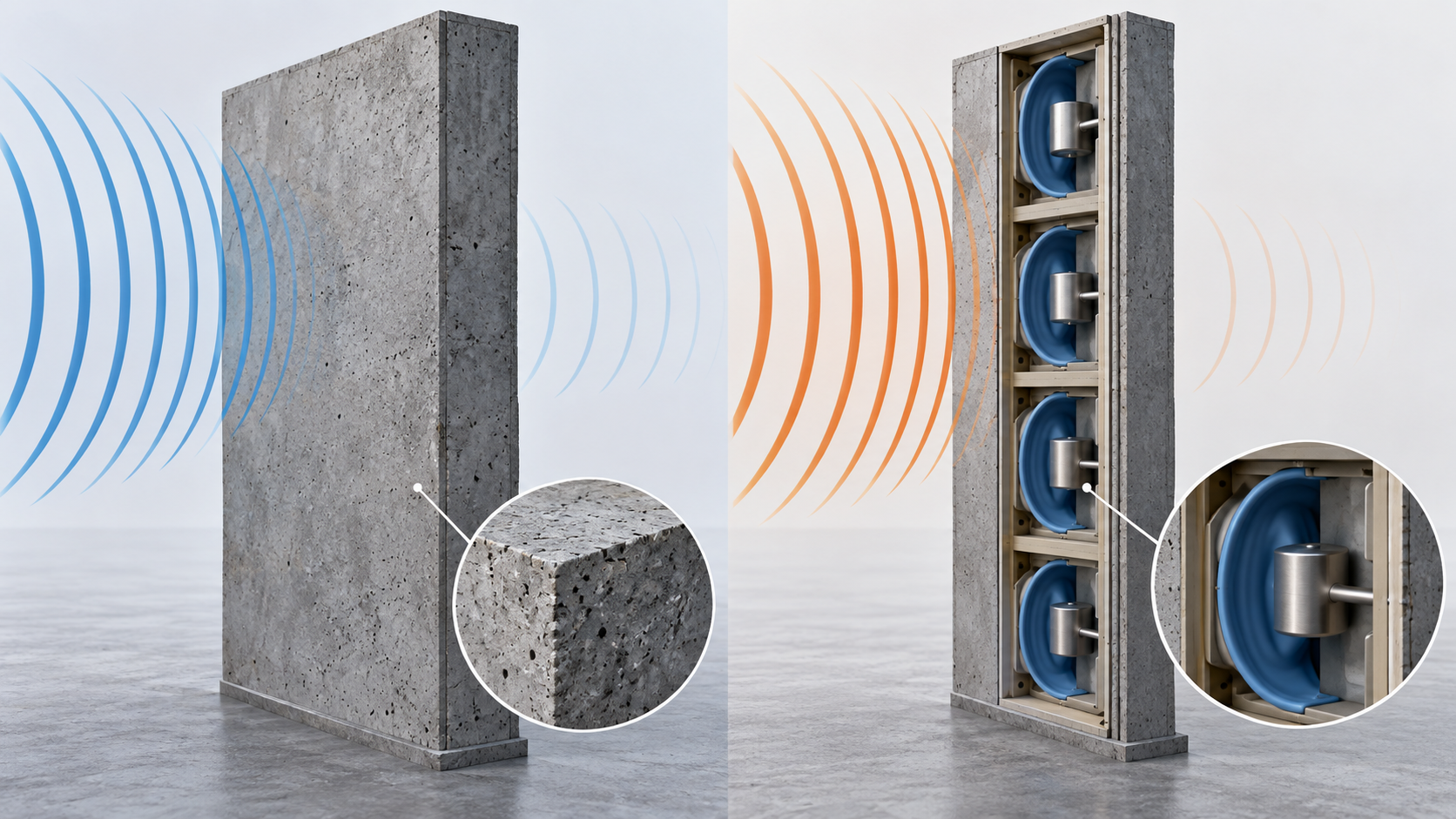
View the original SVG schematic and exact annotations
On the practical side, in an announcement dated 6 January 2020 (US time), Nissan Motor showed at CES 2020 an “acoustic meta-material” in which a combination of a lattice structure and plastic film controls air vibrations to limit the transmission of wide-band noise, such as road and engine noise, in the 500–1200 Hz range. The company says it weighs one-fourth as much as the heavy rubber board mostly used to isolate this band while providing the same degree of sound isolation, and that its mass-production cost competitiveness is almost the same as, or possibly better than, current materials (manufacturer’s stated value; the basis of comparison, test method and effect in real vehicles are not given in the announcement)Sourced [Source 22]. Nissan also says it began research on meta-material technology around 2008Sourced [Source 22].
Working out the sound wavelengths: about 0.69 m at 500 Hz and about 0.29 m at 1200 Hz (taking the speed of sound in air as 343 m/s), and about 0.86 m at 400 Hz for Liu et al.Our calculation. A 2 cm slab is about 1/43 of the wavelength at 400 HzOur calculation. The relationship is clear: a thin plate controls a wavelength orders of magnitude longer than the 10.7 mm wavelength of electromagnetic waves at 28 GHz.
For elastic waves (vibration in solids), Hussein et al. organise “phononic” media, which have periodicity in the constituent materials, the internal geometry or the boundary conditions, as systems describable by a frequency band structure like an electronic band diagram, and survey a field that runs from trusses and ribbed shells to phononic crystals and metamaterialsSourced [Source 24]. Examples of vibration-damping products could not be confirmed in primary sources, so none are given here.
9. A materials engineer’s view 2: resonances drift
In a locally resonant structure, the frequency at which insulation rises is set by membrane tension, thickness, the attached mass and the lattice size. Yang et al. state that the eigenfrequencies can be tuned by a small mass placed at the centre of the membraneSourced [Source 21]. Inference: turned around, scatter in mass, in the membrane’s elastic modulus and in the mounting tension is likely to appear as a shift of the insulation peak. In mass production, film-thickness tolerance, the change of elastic modulus with temperature and humidity, and sagging with age could directly affect a narrow-band performance (published material gave no figures for these effects that we could confirm).
Laboratory versus real installation: the scope of ISO 10140-2 states that the results of laboratory measurements are not applicable directly to the field situation without accounting for other factors such as flanking transmission, boundary conditions and total loss factorSourced [Source 29]. In a membrane-type structure whose eigenmodes are set by how the plate is clamped at its edges, the mounting boundary conditions become part of the material’s performance (our commentary).
Common ground with electromagnetic waves: as frequency rises, the wavelength shortens and the structure’s dimensions shrink in proportion (Chapter 4). In electromagnetic metasurfaces, dimensional tolerance in the elements matters as a ratio to the wavelength (our commentary).
10. Laboratory performance versus deployment
Here we sort the above into “what was shown in the laboratory or demonstration” and “what deployment asks”. The right-hand column gives the sources in the reference list.
| Aspect | Shown in laboratory or demonstration | What deployment asks | Source and label |
|---|---|---|---|
| Bandwidth | Absorbance above 88% is a measurement at one frequency, 11.5 GHz. The cloak was a demonstration for the narrow band the theory assumed. Locally resonant insulation is in the band between resonances | Whether performance holds across the whole band in use, as angle and polarisation change. There is a fundamental limit between thinness and bandwidth (Chapter 5) | [6] [3] [21] [7] Sourced |
| Sample size | A small prototype sample (2021), a trial film for window glass, about 50 cm square (2025) | The number of elements when tiling a surface several metres across (about 8,650 on a 50 cm square at 28 GHz and half-wavelength pitch), uniformity, and the effect of seams on the radio waves | [17] [16] [18] Sourced; element count is Our calculation |
| Measurement environment | Anechoic and radio-wave chambers; measurements matched the model | Whether the effect appears in a field with many reflections and scatterers, with interference from other paths and at non-line-of-sight places | [17] [11] Sourced; the field effect is commentary |
| Control | From per-element control signals to a design that switches the focus with the same signal to every element (NTT DOCOMO and AGC) | How to estimate channels and control the RIS in real time is named as a question RIS must answer | [16] [10] Sourced |
| What it is compared with | A single measurement (improvement in received power) | Whether it is chosen over existing means (more base stations, repeaters, the 3GPP network-controlled repeater) on cost, performance and operation | [12] [14] Sourced (including a preprint) |
| Power and installation | Portable, driven from a solar panel and battery (about 50 cm square, about 8 kg) | Long-term outdoor durability, wind, rain and temperature effects, maintenance. Not confirmed in published material | [18] Sourced; durability is Not yet confirmed |
| Weight and cost of sound insulation | The same insulation at one-fourth the weight, with mass-production cost competitiveness almost the same or better (manufacturer’s stated value) | The conditions of the comparison (test method, frequency band, panel construction), the effect in real vehicles, long-term ageing | [22] Sourced (a company claim) |
| Standardisation | ETSI group reports (001–005). 3GPP studied the network-controlled repeater (TR 38.867) | A preprint states that RIS did not become a 3GPP study item. Standardisation is a future matter | [13] [14] [12] Sourced / Not yet confirmed |
11. Limits, and what could not be confirmed
(1) How far it has been put into practice
What has been published are results at the stage of laboratory measurement, demonstration and field trial. The scale of commercial deployment, prices and long-term reliability could not be confirmed from published primary sources.
(2) Details of element structure and materials
The element pitch, element count and millimetre-wave dielectric loss of the liquid-crystal layer in the JDI/KDDI reflector, and the materials and element dimensions of the NTT DOCOMO/AGC metasurface lens, could not be confirmed from the announcements. The lattice dimensions, film material and measurement conditions of Nissan’s acoustic metamaterial also could not be confirmed from its announcement.
(3) What 3GPP and ETSI contain
We checked the text of 3GPP TR 38.867 V18.0.0. How RIS came not to become a study item in Releases 18 and 19 rests on the statement in the preprint by Åström et al.; we did not check the 3GPP meeting records themselves. We also did not check the text of the ETSI reports (GR RIS 001–005) and limit ourselves to ETSI’s announcement of 25 April 2025.
(4) The texts of standards
We have not checked the texts (which are paid) of IEC 62431, JIS R 1679, ISO 10140-2, ISO 354, ISO 10534-2, ISO 717-1, IEEE 149 and others, except the foreword, scope and contents of the JIS R 1679 preview. Test procedures, pass criteria and calibration are not described.
(5) Other applications
Optical metalenses (see our explainer on metalenses and flat optics), plasmonics (see our explainer on plasmonics and nanophotonics), thermal-radiation and radiative-cooling metasurfaces (see our explainer on thermal control materials and radiative cooling), real stealth systems and mass-produced active metamaterials are not covered here.
- A metamaterial is a structure designed through its dimensions. The operating frequency is tied to those dimensions, which scale with wavelength (about 10.7 mm at 28 GHz, about 0.69 m for a 500 Hz sound)Our calculation
- For electromagnetic waves, the reflection direction or focus can be designed through the element layout. The film-shaped lens of NTT DOCOMO and AGC gave more than 24 dB over float glass at the focus at 27.6 GHz (the companies’ announcement; normal incidence, a value at the focus)Sourced
- For sound, a light, thin structure exceeds the mass law in a particular band. But the band is narrow, and insulation falls near the eigenmodesSourced
- The obstacles to deployment are bandwidth, loss, control and what the technology is compared with. A thin broadband absorber has a lower bound on thickness, and one account is that RIS did not become a 3GPP study itemSourced (including a preprint)
- Standards are test methods, and we could not confirm an international standard aimed at metamaterials in general. Read the existing standards for radio-wave absorbers, sound insulation and sound absorption, with their conditionsSourced
12. How to read evaluations and standards
What is measured: for radio waves, reflectivity (dB), absorption, the phase and amplitude of reflection and transmission, and antenna gain and radiation pattern, measured in a free-space set-up (horn antennas and a network analyser, an anechoic chamber). For sound, transmission loss (dB), sound absorption coefficient and surface impedance, measured in a reverberation room, in a pair of laboratory rooms with the specimen mounted between them, or in an impedance tube. We found no ISO, IEC or IEEE standard that names metamaterials in general. In practice the existing standards for each use (radio-wave absorbers, antennas, sound insulation of building elements, sound absorbers) are usedSourced (a statement of what could not be confirmed).
| Item evaluated | ISO | IEC / IEEE | JIS | ASTM | What changes the value with measurement conditions |
|---|---|---|---|---|---|
| Millimetre-wave reflectivity (free-space measurement of absorbers and reflectors)Sourced | Could not be confirmed | IEC 62431:2008 (Reflectivity of electromagnetic wave absorbers in millimetre wave frequency – Measurement methods). Edition 1.0, published 9 July 2008. Reflectivity 0 to −50 dB, incident angle 0° to 80°. It replaces IEC/PAS 62431 [25] | JIS R 1679 (Measurement methods for reflectivity of electromagnetic wave absorber in millimetre wave frequency). The edition established on 20 June 2007 was checked in a Japanese Standards Association preview. 30–300 GHz, reflectivity 0 to −50 dB, incident angle 0° to 80°. Its foreword says that at establishment there was no corresponding international standard [26, 27] | Could not be confirmed | Frequency, angle of incidence, polarisation, calibration with a reference metal plate, coupling between antennas, dynamic range (from the titles of JIS R 1679’s annexes), specimen size |
| Antenna gain and radiation patternSourced | Could not be confirmed | IEEE 149-2021 (IEEE Recommended Practice for Antenna Measurements). Approved 23 September 2021, published 18 February 2022, supersedes 149-1977. The antenna under test is treated as passive, linear and reciprocal [28] | Could not be confirmed | Could not be confirmed | Measurement distance (far field or near field), reflections in the range, polarisation, calibration. How far this assumption holds for a surface whose state is switched was not checked |
| Communication-level evaluation of RISNot yet confirmed | Could not be confirmed | Could not be confirmed. For reference: ETSI group reports GR RIS 001–005 (announced 25 April 2025; reports, not standards) [13]. 3GPP TR 38.867 V18.0.0 (September 2022, a study report on network-controlled repeaters) [14] | Could not be confirmed | Could not be confirmed | Channel model, near field and far field, radiation patterns of the elements and the RIS, anechoic chamber or field site |
| Airborne sound insulation (laboratory transmission loss)Sourced | ISO 10140-2:2021 (Laboratory measurement of sound insulation of building elements – Part 2: Measurement of airborne sound insulation). Edition 2, April 2021, confirmed in 2026. Results in one-third-octave bands are rated as a single number under ISO 717-1:2020 (Edition 4, December 2020) [29, 30] | Could not be confirmed | JIS A 1416 (Japanese title: method of laboratory measurement of airborne sound insulation of building elements; our translation). The year of the edition and its correspondence to the ISO standard were not checked [33] | ASTM E90 (Standard Test Method for Laboratory Measurement of Airborne Sound Transmission Loss of Building Partitions and Elements). The year of the edition was not checked. Title and subject confirmed from a listing on the ANSI Webstore [36] | Mounting and size of the specimen, frequency band, and the condition of test rooms in which flanking transmission is suppressed. ISO 10140-2 states that the results should not be applied to the field without accounting for flanking transmission, boundary conditions and total loss factor |
| Sound absorption coefficient (reverberation room, diffuse field)Sourced | ISO 354:2003 (Measurement of sound absorption in a reverberation room). Edition 2, May 2003, confirmed in 2024. It states that it is not intended for measuring weakly damped resonators [31] | Could not be confirmed | JIS A 1409 (Japanese title: method of measuring sound absorption coefficient in a reverberation room; our translation). The year of the edition and its correspondence to the ISO standard were not checked [34] | Could not be confirmed | Specimen size and mounting, diffuse-field incidence, frequency band |
| Sound absorption coefficient and surface impedance (impedance tube, normal incidence)Sourced | ISO 10534-2:2023 (Determination of acoustic properties in impedance tubes – Part 2: Two-microphone technique for normal sound absorption coefficient and normal surface impedance). Edition 2, 2023. It states that the values are not comparable with the random-incidence values of ISO 354 [32] | Could not be confirmed | JIS A 1405-2 (Japanese title: measurement of sound absorption coefficient and impedance by acoustic tube, Part 2: transfer-function method; our translation). The year of the edition and its correspondence to the ISO standard were not checked [35] | ASTM E1050 (Standard Test Method for Impedance and Absorption of Acoustical Materials Using a Tube, Two Microphones and a Digital Frequency Analysis System). Described on an Intertek explanatory page as a method for normal-incidence absorption coefficient and normal specific acoustic impedance ratio [37] | Normal incidence only. The specimen is the same size as the tube cross-section. The upper frequency limit is set by the tube diameter |
| Terminology and characterisation of metamaterials in generalSourced | Could not be confirmed | Could not be confirmed | Could not be confirmed | Could not be confirmed | Within what we searched, we found no ISO, IEC or IEEE standard that names metamaterials (a statement of what could not be confirmed) |
Which standard we match to which item is our own arrangement (Our calculation). Numbers and titles were checked on the official ISO page for ISO, the IEC Webstore for IEC, the IEEE SA page for IEEE, and the JISC JIS search for JIS. The two ASTM standards were checked on non-ASTM pages; the ASTM website was not opened.
How the standards differ in standing
- ISO, IEC and IEEE are international or internationally used standards; JIS is Japan’s national standard. The foreword of JIS R 1679 says that when it was established (2007) there was no corresponding international standard [27]. IEC 62431 was published in July 2008, but the relationship between the two and the current edition of the JIS were not checked here
- ASTM is a US-centred standards organisation. A property with the same name does not necessarily use the same method or conditions. ASTM E1050 and ISO 10534-2 are both normal-incidence impedance-tube methods, but we did not confirm that editions or details match
- ETSI and 3GPP are telecommunications standards bodies, and their documents are not material test standards. The RIS documents are technical reports or study reports, to be kept distinct from specifications [13, 14]
Cautions in reading the standards
- A standard is a test method, not a guarantee of performance. IEC 62431 and JIS R 1679 are methods for measuring reflectivity; we did not check whether they go as far as evaluating the operation of a surface whose reflection direction is switched. ISO 354 states that it is not intended for measuring the absorption characteristics of weakly damped resonators, so you need to confirm which standard a resonant structure was measured with (whether a resonant structure counts as a “weakly damped resonator” is our inference and has not been checked)
- The same named property can differ with the standard and its edition. The normal-incidence absorption coefficient of ISO 10534-2 is not comparable with the random-incidence coefficient of ISO 354 [32]. A single-number rating (ISO 717-1) merges band-by-band values, so the narrow peaks and dips of Fig. 6 are hard to see in a single number (our commentary)
- Read a manufacturer’s value together with the standard, edition and test conditions it follows. Nissan’s “the same insulation at one-fourth the weight” has no standard or conditions in the announcement [22]. The “above 24 dB” of NTT DOCOMO and AGC is received power at the focus with float glass taken as 0 dB, under normal incidence at 27.6 GHz [16]
- The gap between a standard’s range and conditions of use: laboratory standard results do not include flanking transmission or the reflective environment of the field [29]
13. Glossary
- Metamaterial
- An artificial medium of structures smaller than the wavelength, arranged periodically so that waves behave in ways the composition alone would not give.
- Metasurface
- The two-dimensional version of a metamaterial: a thin surface whose elements vary the phase and other properties.
- Effective medium
- The properties seen when fine detail is averaged and the structure is treated as one uniform medium.
- Unit cell
- The smallest repeating unit of a periodic structure.
- RIS
- Reconfigurable intelligent surface: a surface with switchable elements that adaptively changes, for example, the reflection direction.
- NCR
- Network-controlled repeater: an RF repeater that receives control information from the base station (3GPP Release 18).
- Coding metamaterial
- An approach that arranges elements with phase 0 and π as “0” and “1” and controls waves through the sequence.
- Mass law
- The relation that the heavier a wall is, the better it blocks sound.
- Local resonance
- Resonance of small resonators inside a structure that changes its effective elastic constants.
- Transmission loss
- The amount of sound lost in passing through a wall (dB). Larger means better insulation.
- Reflectivity
- The strength of reflection relative to the incident wave (dB). A larger negative value means more absorption.
- Coverage hole
- A place that base-station radio waves hardly reach.
14. References (primary sources)
- Smith D. R., Pendry J. B., Wiltshire M. C. K. “Metamaterials and Negative Refractive Index”, Science 305, 788–792 (2004), DOI 10.1126/science.1096796 — doi.org/10.1126/science.1096796
- Pendry J. B. “Negative Refraction Makes a Perfect Lens”, Phys. Rev. Lett. 85, 3966–3969 (2000), DOI 10.1103/PhysRevLett.85.3966 — doi.org/10.1103/PhysRevLett.85.3966
- Schurig D. et al. “Metamaterial Electromagnetic Cloak at Microwave Frequencies”, Science 314, 977–980 (2006), DOI 10.1126/science.1133628 — doi.org/10.1126/science.1133628
- Yu N. et al. “Light Propagation with Phase Discontinuities: Generalized Laws of Reflection and Refraction”, Science 334, 333–337 (2011), DOI 10.1126/science.1210713 — doi.org/10.1126/science.1210713
- Cui T. J. et al. “Coding metamaterials, digital metamaterials and programmable metamaterials”, Light: Science & Applications 3, e218 (2014), DOI 10.1038/lsa.2014.99 — doi.org/10.1038/lsa.2014.99
- Landy N. I. et al. “Perfect Metamaterial Absorber”, Phys. Rev. Lett. 100, 207402 (2008), DOI 10.1103/PhysRevLett.100.207402 — doi.org/10.1103/PhysRevLett.100.207402
- Rozanov K. N. “Ultimate thickness to bandwidth ratio of radar absorbers”, IEEE Trans. Antennas Propag. 48, 1230–1234 (2000), DOI 10.1109/8.884491 — doi.org/10.1109/8.884491
- Khurgin J. B. “How to deal with the loss in plasmonics and metamaterials”, Nat. Nanotechnol. 10, 2–6 (2015), DOI 10.1038/nnano.2014.310 — doi.org/10.1038/nnano.2014.310
- Di Renzo M. et al. “Smart Radio Environments Empowered by Reconfigurable Intelligent Surfaces: How It Works, State of Research, and The Road Ahead”, IEEE J. Sel. Areas Commun. 38, 2450–2525 (2020), DOI 10.1109/JSAC.2020.3007211 — doi.org/10.1109/JSAC.2020.3007211
- Björnson E., Özdogan Ö., Larsson E. G. “Reconfigurable Intelligent Surfaces: Three Myths and Two Critical Questions”, IEEE Commun. Mag. 58(12), 90–96 (2020), DOI 10.1109/MCOM.001.2000407 — doi.org/10.1109/MCOM.001.2000407
- Tang W. et al. “Wireless Communications With Reconfigurable Intelligent Surface: Path Loss Modeling and Experimental Measurement”, IEEE Trans. Wireless Commun. 20, 421–439 (2021), DOI 10.1109/TWC.2020.3024887 — doi.org/10.1109/TWC.2020.3024887
- Åström M. et al. “RIS in Cellular Networks — Challenges and Issues”, arXiv:2404.04753 (preprint, version 2 of 7 November 2024, not peer-reviewed) — arxiv.org/abs/2404.04753
- ETSI “ETSI releases new Reports on Reconfigurable Intelligent Surfaces” (25 April 2025) — etsi.org/newsroom/news/2522
- 3GPP “TR 38.867 V18.0.0 (2022-09) Study on NR network-controlled repeaters (Release 18)” — 3gpp.org/ftp/Specs/archive/38_series/38.867
- Nippon Telegraph and Telephone Corporation and NTT DOCOMO News release on the demonstration of user-tracking metasurface control (12 November 2021; in Japanese) — group.ntt/jp/newsrelease/2021/11/12/211112b.html
- NTT DOCOMO and AGC Press release on turning window glass into a radio-wave lens with metasurface technology (26 January 2021, with the annex of experimental results; in Japanese) — agc.com/news/pdf/20210126.pdf
- Japan Display and KDDI Research Press release on a liquid-crystal metasurface reflector whose reflection direction can be changed (7 October 2021; in Japanese) — j-display.com/news/release/detail/20211007000000.html
- Japan Display, KDDI and KDDI Research Press release on reflecting millimetre waves between outdoor buildings with a liquid-crystal reflector (28 February 2025; in Japanese) — j-display.com/news/release/detail/20250227161354.html
- Liu Z. et al. “Locally Resonant Sonic Materials”, Science 289, 1734–1736 (2000), DOI 10.1126/science.289.5485.1734 — doi.org/10.1126/science.289.5485.1734
- Active Metamaterials Roadmap (multiple authors) “The 2024 Active Metamaterials Roadmap”, arXiv:2411.09711 (preprint) — arxiv.org/abs/2411.09711
- Yang Z. et al. “Membrane-Type Acoustic Metamaterial with Negative Dynamic Mass”, Phys. Rev. Lett. 101, 204301 (2008), DOI 10.1103/PhysRevLett.101.204301 — doi.org/10.1103/PhysRevLett.101.204301
- Nissan Motor Co., Ltd. “Nissan shows new, lightweight noise-reducing technology at CES” (6 January 2020) — global.nissannews.com/releases/nissan-shows-new-lightweight-noise-reducing-technology-at-ces
- Ma G., Sheng P. “Acoustic metamaterials: From local resonances to broad horizons”, Sci. Adv. 2, e1501595 (2016), DOI 10.1126/sciadv.1501595 — doi.org/10.1126/sciadv.1501595
- Hussein M. I., Leamy M. J., Ruzzene M. “Dynamics of Phononic Materials and Structures: Historical Origins, Recent Progress, and Future Outlook”, Appl. Mech. Rev. 66, 040802 (2014), DOI 10.1115/1.4026911 — doi.org/10.1115/1.4026911
- IEC “IEC 62431:2008” product page (IEC Webstore) — webstore.iec.ch/en/publication/7006
- Japanese Industrial Standards Committee (JISC) JIS search listing for “JIS R 1679” — jisc.go.jp (JIS R 1679)
- Japanese Standards Association “JIS R 1679:2007” preview (foreword, scope, contents; in Japanese) — webdesk.jsa.or.jp/preview/pre_jis_r_01679_000_000_2007_j_ed10_ch.pdf
- IEEE SA “IEEE 149-2021” page — standards.ieee.org/ieee/149/6667
- ISO “ISO 10140-2:2021” page — iso.org/standard/79487.html
- ISO “ISO 717-1:2020” page — iso.org/standard/77435.html
- ISO “ISO 354:2003” page — iso.org/standard/34545.html
- ISO “ISO 10534-2:2023” page — iso.org/standard/81294.html
- Japanese Industrial Standards Committee (JISC) JIS search listing for “JIS A 1416” — jisc.go.jp (JIS A 1416)
- Japanese Industrial Standards Committee (JISC) JIS search listing for “JIS A 1409” — jisc.go.jp (JIS A 1409)
- Japanese Industrial Standards Committee (JISC) JIS search listing for “JIS A 1405” (Parts 1 and 2) — jisc.go.jp (JIS A 1405)
- ANSI Webstore (a non-ASTM sales page) Listing giving the title and subject of ASTM E90 — webstore.ansi.org/standards/astm/astme9099
- Intertek (a non-ASTM explanatory page) Explanation of the title and scope of ASTM E1050 — intertek.com/building/standards/astm-e1050
15. Claim-to-source audit
| Claim in the text | Basis | Label |
|---|---|---|
| Metamaterials show electromagnetic properties absent in conventional materials (artificial magnetism, negative refractive index), and the value of widening what counts as a material | Review by Smith et al. (2004) Reference 1 https://doi.org/10.1126/science.1096796 | Sourced |
| The theory of a negative-index slab (superlens), feasible in the microwave band, and the simulation of a silver slab resolving objects a few nanometres across | Pendry (2000) Reference 2 https://doi.org/10.1103/PhysRevLett.85.3966 | Sourced |
| A metamaterial cloak reducing scattering and shadow of a copper cylinder in the microwave band; the theory holding a cloak possible at least over a narrow band | Schurig et al. (2006) Reference 3 https://doi.org/10.1126/science.1133628 | Sourced |
| Arrays with abrupt wavelength-scale phase changes, generalised laws of reflection and refraction, metallic antennas on silicon, optical vortices | Yu et al. (2011) Reference 4 https://doi.org/10.1126/science.1210713 | Sourced |
| Coding with elements of phase 0 and π as 0 and 1, diode-switched elements, programming with an FPGA | Cui et al. (2014) Reference 5 https://doi.org/10.1038/lsa.2014.99 | Sourced |
| An absorber with electric and magnetic resonators, predicted absorbance 96%, measured above 88% at 11.5 GHz, metallic elements only so the substrate can be chosen | Landy et al. (2008) Reference 6 https://doi.org/10.1103/PhysRevLett.100.207402 | Sourced |
| The lower bound on the thickness-to-bandwidth ratio of metal-backed absorbers; the least thickness of a 10 dB broadband dielectric absorber is 1/17 of the largest operating wavelength | Abstract of Rozanov (2000) Reference 7 https://doi.org/10.1109/8.884491 | Sourced |
| Metal losses affect the performance of every structure, and how they are dealt with determines how far practical applications are found | Khurgin (2015) Reference 8 https://doi.org/10.1038/nnano.2014.310 | Sourced |
| Ways of realising RIS (half-wavelength antenna arrays, metamaterial type); many elements but few, cheap components, usually no power amplifiers; C-SWaP | Di Renzo et al. (2020) Reference 9 https://doi.org/10.1109/JSAC.2020.3007211 | Sourced |
| Three myths and two critical questions on RIS (use case; channel estimation and real-time control) | Björnson et al. (2020) Reference 10 https://doi.org/10.1109/MCOM.001.2000407 | Sourced |
| Free-space path-loss models for RIS; measurements of three fabricated RISs in an anechoic chamber matching the models | Tang et al. (2021) Reference 11 https://doi.org/10.1109/TWC.2020.3024887 | Sourced |
| That RIS was not continued as a 3GPP Release 18 and 19 study item, and the comparison with the network-controlled repeater (as stated in a preprint) | Åström et al. (arXiv, version 2, November 2024) Reference 12 https://arxiv.org/abs/2404.04753 | Sourced |
| The titles of ETSI RIS group reports GR RIS 001–005 (announced 25 April 2025) and an outline of 004 | ETSI announcement Reference 13 https://www.etsi.org/newsroom/news/2522-etsi-releases-new-reports-on-reconfigurable-intelligent-surfaces/ | Sourced |
| 3GPP TR 38.867 V18.0.0 (September 2022): the assumed NCR (in-band RF repeater, single-hop and stationary, transparent to UEs, cost efficiency) and the scope of side control information | 3GPP TR 38.867 Reference 14 https://www.3gpp.org/ftp/Specs/archive/38_series/38.867/38867-i00.zip | Sourced |
| NTT and NTT DOCOMO’s experiment on dynamically changing the reflection direction (AGC’s RIS reflector), the “world first” (the announcers’ claim), further study as a leading candidate | NTT and NTT DOCOMO news release (12 November 2021) Reference 15 https://group.ntt/jp/newsrelease/2021/11/12/211112b.html | Sourced |
| NTT DOCOMO and AGC’s metasurface lens (27.6 GHz; above 24 dB over float glass; heat-shielding glass −29 dB, about 0 dB, about 24 dB; the 29.5 GHz dynamic lens values; same control signal to all elements; experiment dates 14–18 December 2020; the heat-shielding film reflects radio waves) | NTT DOCOMO and AGC press release (annex) Reference 16 https://www.agc.com/news/pdf/20210126.pdf | Sourced |
| The liquid-crystal metasurface reflector (liquid-crystal layer between reflecting elements and ground plane, permittivity changed by voltage), a small sample tested in an anechoic chamber, “world first” (the announcers’ claim) | JDI and KDDI Research press release (7 October 2021) Reference 17 https://www.j-display.com/news/release/detail/20211007000000.html | Sourced |
| The portable 28 GHz liquid-crystal reflector (about 50 cm square, about 8 kg, smartphone control, Nishi-Shinjuku, 21 December 2024 to 31 March 2025, solar-panel and battery operation) and the stated approach toward practical use | JDI, KDDI and KDDI Research press release (28 February 2025) Reference 18 https://www.j-display.com/news/release/detail/20250227161354.html | Sourced / Not yet confirmed |
| A locally resonant sonic crystal (lattice constant two orders smaller than the wavelength), a 2 cm slab breaking the mass law by one or more orders of magnitude at 400 Hz | Liu et al. (2000) Reference 19 https://doi.org/10.1126/science.289.5485.1734 | Sourced |
| That the complexity of active metamaterials is a challenge for progress beyond theory and laboratory experiments | 2024 Active Metamaterials Roadmap (preprint) Reference 20 https://arxiv.org/abs/2411.09711 | Sourced |
| A membrane-type acoustic metamaterial, about 200 times beyond the mass law at 100–1000 Hz, eigenfrequencies tuned by a small mass, near-total reflection between two eigenmodes | Yang et al. (2008) Reference 21 https://doi.org/10.1103/PhysRevLett.101.204301 | Sourced |
| Nissan’s acoustic meta-material (lattice and plastic film, 500–1200 Hz, one-fourth the weight, cost competitiveness, research started around 2008, CES 2020). The manufacturer’s stated values | Nissan news release (6 January 2020) Reference 22 https://global.nissannews.com/releases/nissan-shows-new-lightweight-noise-reducing-technology-at-ces | Sourced |
| The development of acoustic metamaterials (local resonance, phase manipulation, superabsorption, active control, elastic media and others) | Ma and Sheng (2016) Reference 23 https://doi.org/10.1126/sciadv.1501595 | Sourced |
| Description of phononic media by a frequency band structure, from trusses to metamaterials | Hussein et al. (2014) Reference 24 https://doi.org/10.1115/1.4026911 | Sourced |
| Number, title and edition: IEC 62431:2008 (Edition 1.0, 9 July 2008) | IEC Webstore Reference 25 https://webstore.iec.ch/en/publication/7006 | Sourced |
| Number and title: JIS R 1679 (Japanese title on the JISC listing) | JISC JIS search Reference 26 https://www.jisc.go.jp/app/jis/general/GnrJISNumberNameSearchList?show&jisStdNo=R1679 | Sourced |
| JIS R 1679:2007: date of establishment (20 June 2007), scope (30–300 GHz, 0 to −50 dB, 0° to 80°), the foreword (no corresponding international standard at establishment), the annex titles, and the English title | Japanese Standards Association preview Reference 27 https://webdesk.jsa.or.jp/preview/pre_jis_r_01679_000_000_2007_j_ed10_ch.pdf | Sourced |
| Number and title: IEEE 149-2021 (approval and publication dates, previous edition, assumption about the antenna under test) | IEEE SA Reference 28 https://standards.ieee.org/ieee/149/6667/ | Sourced |
| Number, title and edition: ISO 10140-2:2021 (Edition 2, April 2021, confirmed 2026; results not directly applicable to the field) | ISO Reference 29 https://www.iso.org/standard/79487.html | Sourced |
| Number, title and edition: ISO 717-1:2020 (Edition 4, December 2020; single numbers from one-third-octave bands) | ISO Reference 30 https://www.iso.org/standard/77435.html | Sourced |
| Number, title and edition: ISO 354:2003 (Edition 2, May 2003, confirmed 2024; weakly damped resonators outside its intent) | ISO Reference 31 https://www.iso.org/standard/34545.html | Sourced |
| Number, title and edition: ISO 10534-2:2023 (Edition 2, normal incidence, not comparable with ISO 354) | ISO Reference 32 https://www.iso.org/standard/81294.html | Sourced |
| Number and title: JIS A 1416 (Japanese title on the JISC listing) | JISC JIS search Reference 33 https://www.jisc.go.jp/app/jis/general/GnrJISNumberNameSearchList?show&jisStdNo=A1416 | Sourced |
| Number and title: JIS A 1409 (Japanese title on the JISC listing) | JISC JIS search Reference 34 https://www.jisc.go.jp/app/jis/general/GnrJISNumberNameSearchList?show&jisStdNo=A1409 | Sourced |
| Number and title: JIS A 1405-1 and A 1405-2 (Japanese titles on the JISC listing) | JISC JIS search Reference 35 https://www.jisc.go.jp/app/jis/general/GnrJISNumberNameSearchList?show&jisStdNo=A1405 | Sourced |
| Title and subject of ASTM E90 (confirmed on a non-ASTM sales page; the ASTM website was not opened) | ANSI Webstore Reference 36 https://webstore.ansi.org/standards/astm/astme9099 | Sourced |
| Title and scope of ASTM E1050 (confirmed on a non-ASTM explanatory page; the ASTM website was not opened) | Intertek explanatory page Reference 37 https://www.intertek.com/building/standards/astm-e1050/ | Sourced |
| Wavelengths (28 GHz: about 10.7 mm; 39 GHz: about 7.7 mm), element counts in a 50 cm square at half-wavelength pitch (about 8,650; about 16,900), the 1/17 of Rozanov applied to several frequencies (about 17.6, 5.9, 1.8 and 0.63 mm), sound wavelengths (500 Hz: about 0.69 m; 1200 Hz: about 0.29 m; 400 Hz: about 0.86 m), and 2 cm being about 1/43 of the wavelength at 400 Hz | Our calculation. Speed of light 299,792,458 m/s and speed of sound 343 m/s assumed. The element count is a guide under the half-wavelength-pitch assumption, not the element count of any real product. Applying the 1/17 contains our interpretation (inference) that the “largest operating wavelength” is that of the lowest operating frequency | Our calculation |
| The element pitch and count and the millimetre-wave loss of the liquid-crystal layer in the JDI/KDDI reflector, the materials and dimensions of the NTT DOCOMO/AGC lens, the lattice dimensions, film material and test conditions of Nissan’s material, the 3GPP meeting records on RIS, the text of the ETSI reports, the texts of the standards, the performance of real stealth systems, and long-term field durability | Not given, because they could not be confirmed in the primary sources accessible to this investigation | Commentary |
| The readings “a metamaterial is not a new substance but a structure designed through its dimensions”, “dimensional tolerance of elements matters as a ratio to the wavelength”, “scatter in mass, elastic modulus and mounting shows up as peak drift in a resonant structure”, “on windows and facades the conductive-film material and thickness become design trade-offs”, “simplifying control through the materials side is important”, “a single number hides narrow peaks and dips”, and “whether a resonant structure counts as a weakly damped resonator is unchecked” | Our own arrangement and commentary based on the published material; not views expressed by the companies or institutions | Commentary |
| That Figs. 2, 3, 4 and 6 are explanatory drawings, not real data, and that Figs. 1 and 5 are AI-generated images | Note from this article | Commentary |
Last updated 10 October 2026. Sources are limited to primary material (peer-reviewed papers, official pages of 3GPP, ETSI, ISO, IEC, IEEE and JISC, and announcements by the companies and institutions concerned). The texts of standards are paid and could not be checked, apart from the foreword, scope and contents of the JIS R 1679 preview. The ASTM International website was not opened. Because the article includes structural readings and materials-design interpretations, those are marked as Commentary and kept separate from sourced fact. The performance of real stealth systems, details of element structures and materials, the 3GPP meeting records, the text of the ETSI reports and long-term field durability could not be confirmed and are not stated here. Figures from announcements are the stated values of the companies and institutions that made them, and are not meant for ranking experiments that differ in conditions. All figures are explanatory concept graphics. Figs. 2, 3, 4 and 6 are vector drawings; Figs. 1 and 5 are AI-generated images, and none of them shows a real photograph, measured data or a physical product.