TECHNOLOGY EXPLAINER
Ferroelectric and Dielectric Materials
— why “high permittivity” is not the whole story: reading polarization, field and insulation
The capacitance of a capacitor, the “1” and “0” of a memory, and the storage of energy all depend on the polarization inside a dielectric and the electric field it can withstand. This article covers the basics of ferroelectricity, HfO2-based ferroelectric films (for memory), BaTiO3-based multilayer ceramic capacitors (MLCCs) and polymer dielectrics, and sets out, from primary sources, how to read permittivity, loss, dielectric breakdown and the change under DC bias together with their conditions.
- What ferroelectric and dielectric materials are (the short version)
- The basics of ferroelectricity — polarization, hysteresis, Curie temperature
- Reading the metrics — permittivity, loss, breakdown, Pr and Ec
- HfO 2 -based ferroelectric films — memory applications and issues
- BaTiO 3 -based materials and multilayer ceramic capacitors — thin layers and DC bias
- Polymer dielectrics and energy density
- Our calculations: layer field and capacitance, coercive voltage and charge, rewrite life
- Regulation, and how this relates to other articles in the series
- Limits, and what could not be confirmed
- How to read evaluations and standards
- Glossary
- References (primary sources)
- Claim-to-source audit
Sourced = stated in published material (link given)
Our calculation = a figure this article derived, with the assumptions spelled out
Not yet confirmed = a plan or schedule whose outcome has not been confirmed
Materials-design interpretations are marked separately as Commentary. Inference is shown in bold.
The permittivities, polarizations, endurance counts and energy densities quoted here differ by source in sample form (thin film, sintered body, film) and in the frequency, field and temperature of measurement. Please do not read laboratory sample results as the performance of commercial parts or production products. A manufacturer’s stated value is a value under that company’s conditions and is not necessarily a guarantee. This article does not rank materials or companies, and gives no individual advice on medical devices or safety.
1. What ferroelectric and dielectric materials are (the short version)
- A dielectric is a material that polarizes in a field and stores charge: the capacitance of a capacitor is set by the dielectric’s relative permittivity, the electrode area and the dielectric thickness. A ferroelectric is one in which polarization remains even when the field is returned to zeroSourced [Ref. 4]
- The numbers change with the field at which they are measured: a ferroelectric responds nonlinearly to field. In one laboratory result on polycrystalline BaTiO3, a relative permittivity of 2,250 without bias fell to below 750 under a 5 V/µm biasSourced [Ref. 8]
- Performance is not set by “large permittivity” alone: in an MLCC, thinner layers raise capacitance but also the field in each layer; in memory, the margin between coercive field and breakdown field and the rewrite endurance become the issues; in energy storage, the square of the breakdown field acts
Numbers for permittivity, loss and endurance have meaning only when the field, frequency, temperature and sample form at which they were measured are attached. A material chosen by its zero-bias permittivity can perform differently at the bias actually used.
2. The basics of ferroelectricity — polarization, hysteresis, Curie temperature
RAMXEED’s explanation sorts dielectrics, piezoelectrics, pyroelectrics and ferroelectrics as followsSourced [Ref. 4].
- Dielectric: does not conduct electricity but has the ability to store charge internally when placed in a field. Used in capacitors
- Piezoelectric: produces charge under pressure and changes shape under voltage. Used in sensors and actuators (see our explainer on piezoelectric materials and lead-free alternatives)
- Pyroelectric: produces charge with a change of temperature. Used in infrared sensors
- Ferroelectric: polarizes in a field and keeps the polarization after the field is removed. Used in memory elements and sensors
The same explanation notes that a ferroelectric combines several of these properties, so all of them have to be controlled [Ref. 4]. If a voltage is applied to a thin film between electrodes and the polarization is measured, an ordinary dielectric gives a straight line proportional to the field, while a ferroelectric gives a hysteresis curve that depends on past history. A ferroelectric memory uses the positive or negative polarization at zero voltage as “1” and “0” [Ref. 4].
The symbols for reading a ferroelectric curve are these (this article’s commentary): Ps (saturation polarization), Pr (remanent polarization: what remains at zero field) and Ec (coercive field: the field at which the polarization reverses). An antiferroelectric draws a double loop: a field switches it into a ferroelectric-like state, and it returns when the field is removed. Park et al. report that HfO2-based films show both ferroelectric and antiferroelectric behaviour [Ref. 3].
Ferroelectricity is lost above the Curie temperature Tc. RAMXEED’s explanation gives a Tc of 350 °C for PZT [Ref. 4]. A review of BaTiO3-based electrocaloric materials states that the Tc of BaTiO3 is about 120 °C, above room temperatureSourced [Ref. 11]. It is also summarized that polarization switching and domain-wall displacement contribute to the dielectric and piezoelectric properties of ferroelectric ceramics and thin films [Ref. 10].
3. Reading the metrics — permittivity, loss, breakdown, Pr and Ec
| Metric | Meaning | Reading note |
|---|---|---|
| Relative permittivity εr | The ratio to the permittivity of vacuum. The capacitance of an MLCC can be written C = εrε0A/d (A the electrode area, d the dielectric thickness) [Ref. 8] | Changes with frequency, temperature and DC bias. For polycrystalline BaTiO3, 2,250 without DC bias became below 750 at 5 V/µm [Ref. 8]. Distinguish “the zero-bias value” from “the value at the bias in use” |
| Dissipation factor tanδ (dielectric loss) | A quantity expressing the fraction of energy a dielectric loses as heat in AC (a general definition: commentary) | Changes with frequency and temperature. As a reference for Class II BaTiO3-based MLCCs, the paper states a relative permittivity of about 103 and a loss below 3% at 1 kHz [Ref. 8] |
| Breakdown field (dielectric strength) | The maximum field that can be applied to a sample of a given thickness before a destructive discharge occurs [Ref. 12] | Strongly affected by microstructure and band gap. A review says small grains, high density, phase purity and a wide band gap matter [Ref. 12]. The value changes with the test method (AC or DC, ramp rate, electrodes) (Chapter 10) |
| Remanent polarization Pr, coercive field Ec | The polarization at zero field used for ferroelectric memory, and the field that reverses it | HfO2-based films: Pr up to 45 µC/cm2, Ec about 1–2 MV/cm, about ten times that of conventional ferroelectric films [Ref. 3]. In the first report on Si-doped HfO2 (10 nm), Pr was above 10 µC/cm2 and Ec 1 MV/cm [Ref. 1]. These change with film thickness, dopant, electrode and measurement frequency |
| Rewrite endurance (fatigue) | The number of polarization reversals until the read window closes | The HfO2 review cautions that results differ depending on whether the measurement frequency is in the MHz range or the kHz range of reading [Ref. 5]. A manufacturer’s “guaranteed count” and a research “measured fatigue” are different things |
| Energy density | For a linear dielectric the stored energy density is ½ ε0εrE2. For a ferroelectric, the recoverable part is obtained from the P–E curve [Ref. 12] | It acts with the square of the field. A high εr, a large Ps, a small Pr and a high breakdown field are needed [Ref. 12]. Efficiency falls with temperature (see the polymer chapter) |
All Sourced (An et al. [Ref. 8], Park et al. [Ref. 3], Böscke et al. [Ref. 1], reviews [Refs. 5, 12]). The definition of tanδ and the distinction between zero bias and in-use bias are this article’s commentary.
4. HfO2-based ferroelectric films — memory applications and issues
Ferroelectric memory (FeRAM) has long used PZT. According to RAMXEED’s explanation, prototype PZT ferroelectric memories were announced in the United States in the 1980s; PZT was hard to handle in semiconductor fabrication so mass production was difficult, until the company developed a technique to incorporate PZT into semiconductor processes and began volume shipment of a 64 kb FeRAM in October 1999Sourced [Ref. 4].
In 2011, Böscke et al. reported ferroelectricity in thin films of SiO2-doped HfO2. Films 10 nm thick with less than 4 mol% SiO2, when crystallized under mechanical encapsulation, gave an orthorhombic phase with Pr above 10 µC/cm2 at a coercive field of 1 MV/cm; the authors note its compatibility with silicon technologySourced [Ref. 1]. In 2012, Müller et al. reported that a ferroelectric phase also appears in pure ZrO2 films thinner than 10 nm and in HfO2–ZrO2 mixed oxides, and attributed the spontaneous polarization to a noncentrosymmetric orthorhombic phase (space group given as Pbc21) [Ref. 2].
The review by Park et al. (2015) sets out that conventional perovskite ferroelectrics (PZT, BaTiO3, SrBi2Ta2O9) have problems of silicon compatibility, lead, thickness, resistance to hydrogen and a small band gap, whereas HfO2-based films show ferroelectricity or antiferroelectricity with dopants such as Si, Zr, Al, Y, Gd, Sr and La, with Pr up to 45 µC/cm2, Ec of about 1–2 MV/cm, thicknesses below 10 nm and a band gap above 5 eVSourced [Ref. 3].
The review by Schroeder et al. says that in bulk HfO2 the ferroelectric phase is not the one of lowest free energy, so it is crucial to identify the thermodynamic and kinetic drivers of its formation. A main difference from perovskite ferroelectrics is that oxygen ions move on polarization switching, which complicates structural examinationSourced [Ref. 7]. Mikolajick et al. note that, besides HfO2-based materials, ferroelectricity has also been verified in aluminium scandium nitride (AlScN) [Ref. 9].
As prototype examples toward practical use, the HfO2 review introduces the followingSourced [Ref. 5].
- FeFET (transistor type): ferroelectric HfO2 integrated into a 28 nm high-k metal-gate process, with an operating voltage of 6 V, fatigue endurance of 104 cycles and 10-year data retention (as stated in the review)
- FeRAM (capacitor type): a 16 kbit array of TiN/HfO2:Si/TiN capacitors in the back end of a 130 nm CMOS process, with 4 ns programming at 4 V, endurance above 107 cycles and data retention at 125 °C. A 64 kbit HZO (HfO2–ZrO2) array operated with all bits functional at 2 V and 16 ns, and the window remained after 108 cycles at 3.5 V, 100 ns and 85 °C. The endurance above 1018 cycles at 2 V is a prediction from the voltage dependence of time to breakdownNot yet confirmed
- The review states that even the most advanced FeRAM products use the 130 nm node, and that while PZT and SBT FeRAM reach up to 1014 cycles, the fatigue endurance of HfO2-based films is mostly below 1012 cycles, a major obstacle to mass production
The strengths of HfO2-based films are that they are close to the material already used in CMOS as a high-permittivity gate dielectric, that ferroelectricity is retained when they are thin (the review introduces an “inverse size effect” in which ferroelectricity strengthens as thickness falls), a low crystallization temperature (below 450 °C) and a wide band gapSourced [Ref. 5]. On the other hand, the review gives as the main reason why 1014 cycles of fatigue endurance is difficult that the coercive field is close to the breakdown field [Ref. 5]. The large Ec of 1–2 MV/cm means a film of 10 nm can be reversed at a low 1–2 V (calculated in Chapter 7), but also that the film is exposed at every rewrite to a field close to its breakdown field; the benefit and the weakness come from the same property (this article’s commentary). Wake-up (polarization growing at first) is summarized as linked to oxygen vacancies, mixed phases and the choice of electrode [Ref. 5]. From a materials viewpoint, film composition, electrodes (TiN, or oxidation-resistant ones such as TaN and RuO2), deposition and heat treatment are the design items that decide rewrite endurance. This article does not go into the principle of memory or comparison with other emerging memories; see our explainer on nanomemory.
5. BaTiO3-based materials and multilayer ceramic capacitors — thin layers and DC bias
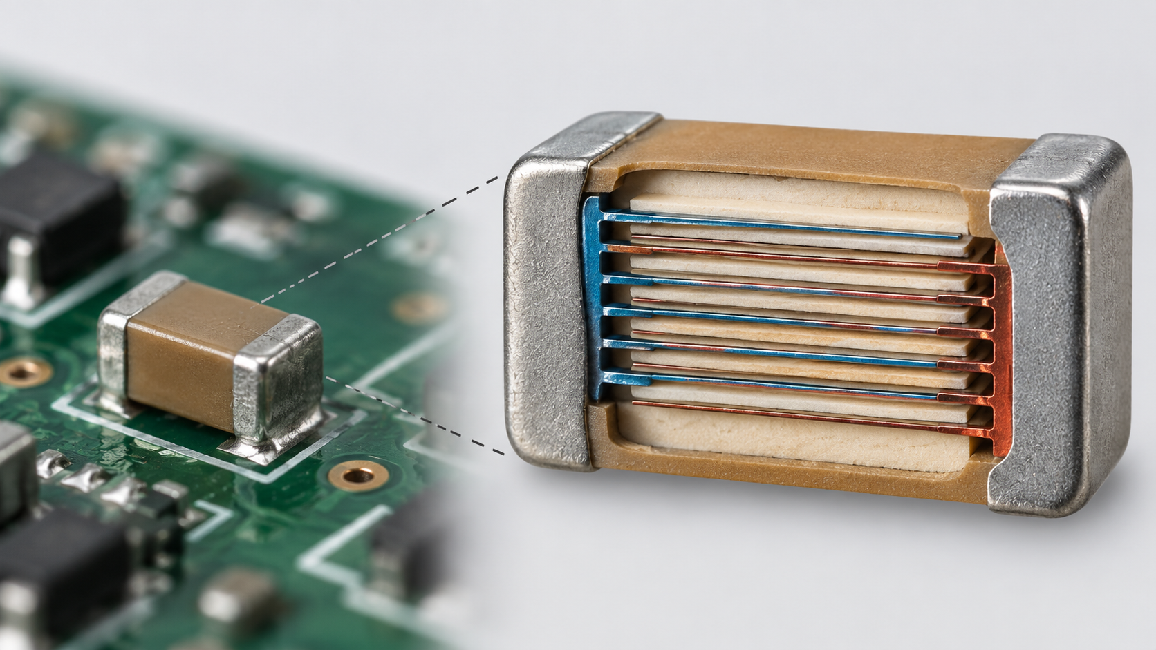
A multilayer ceramic capacitor (MLCC) is a component in which dielectric layers and internal electrode layers are stacked alternately and connected in parallel. The paper by An et al. states that high-permittivity (Class II) MLCCs use ferroelectric polycrystalline BaTiO3 as the standard dielectric, with a relative permittivity of about 103 and a loss below 3% at 1 kHz, dielectric layers under 3 µm each and Ni internal electrodes under 1 µm, and that in state-of-the-art MLCCs for portable devices the dielectric layers are 400 nm or thinnerSourced [Ref. 8]. To keep the Ni internal electrodes from oxidizing, the parts are sintered at 1100–1200 °C in a reducing atmosphere (N2 with 0.1–0.5% H2) [Ref. 8].
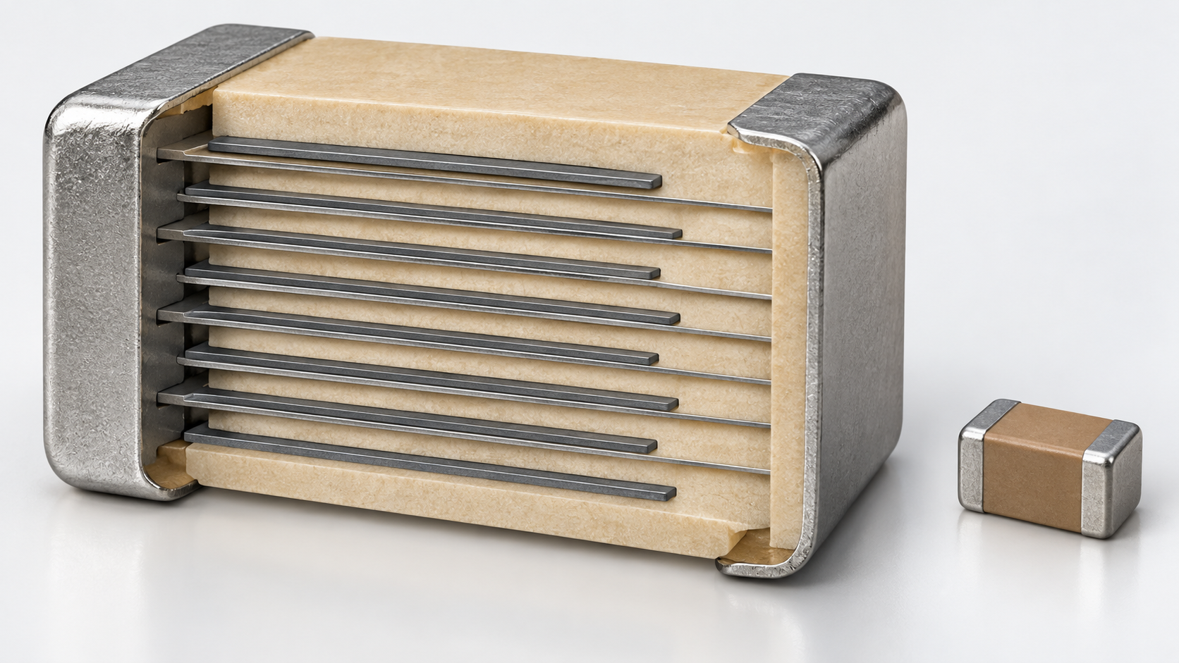
Thinning the layers raises the total capacitance (C = n × Csingle), but raises two issues: keeping the BaTiO3 grains from growing larger than the layer thickness, and the actual field on each layer becoming large. The paper says that CPUs and memory in portable devices powered by lithium-ion batteries run at 0.8–1.8 V, so with layers of 400 nm or less a DC field above 4 V/µm (40 kV/cm) can act on each layerSourced [Ref. 8].
In the paper’s measurements, polycrystalline BaTiO3 with a mean grain size of about 380 nm had a relative permittivity of 2,250 (1 kHz) without DC bias, which fell below 750 under a 5 V/µm bias. Smaller grains reduced the fall under bias, and the paper concludes that the ideal grain size is about 200 nm for maximizing capacitance under a DC bias above 4 V/µm, suggesting a dielectric layer of 200 nm as the next direction [Ref. 8]. The paper also reports suppressing grain growth with additives such as Fe3+ and Ni2+, which are not currently used in MLCC production (a laboratory result, not a commercial specification).
The grade of temperature characteristic is, in the paper’s example, “7R”, meaning a permittivity change within ±15% up to 125 °C [Ref. 8] (an example of an EIA-style temperature characteristic code; we did not confirm its standard number). IEC 60384-21 covers surface-mount multilayer ceramic capacitors of “Class 1” with a defined temperature coefficient, and IEC 60384-22 those of “Class 2”Sourced [Refs. 22, 23].
In the results of An et al., the larger the grain, the larger the zero-bias permittivity (proportional to grain size), but under DC bias that high value is not retained, and samples of smaller grains show a smaller fall under biasSourced [Ref. 8]. For ferroelectric BaTiO3, a strong field is generally thought to align the polarization and leave less room for further response, so the permittivity falls (this article’s commentary). From a materials viewpoint, MLCC material design looks at (1) εr at zero bias, (2) εr at the field in use, (3) the change with temperature, (4) loss, and (5) insulation resistance and reliability together. The paper showed a way to suppress grain growth through segregation of acceptor-type additives at grain boundaries during sintering [Ref. 8]. Thinning the layers is a simultaneous problem of grain size, layer thickness and field, and capacitance does not rise monotonically however thin the layers become (calculated in Chapter 7). For an individual part, check the conditions the datasheet gives (voltage, frequency, temperature, DC bias).
6. Polymer dielectrics and energy density
Li et al. state that polymer dielectrics have higher breakdown strengths and greater reliability than ceramics, but are limited to relatively low working temperaturesSourced [Ref. 14]. A review summarizes that the most important polymer film in commercial capacitors is biaxially oriented polypropylene (BOPP), which is inexpensive and has a very low equivalent series resistance [Refs. 13, 32].
As a guide to energy density, the Nat. Commun. paper gives about 4.0 J/cm3 for the room-temperature discharged energy density of BOPP, described as the commercial benchmark. For heat-resistant polymers it says that an appreciable energy density above 2.0 J/cm3 is accessible only below 150 °CSourced [Ref. 13]. The authors of that paper report an all-organic composite of polyetherimide (PEI, Tg about 217 °C) and other polymers blended with 0.25–0.75 vol.% of a high-electron-affinity molecular semiconductor that reached an energy density of 3.0 J/cm3 with a discharge efficiency of 90% up to 200 °C (the authors’ claim; a result for laboratory-cast films) [Ref. 13].
| Material | Form | Values confirmed, and conditions | Source |
|---|---|---|---|
| BOPP | Biaxially oriented film (commercial) | Room-temperature discharged energy density about 4.0 J/cm3 (quoted by the paper as the commercial benchmark). Use at high temperature is limited | [13] |
| PEI / molecular-semiconductor all-organic composite | Solution-cast film (laboratory) | 3.0 J/cm3 at 200 °C with 90% discharge efficiency (the authors’ claim). A 20 × 30 cm2 film was made and evaluated region by region | [13] |
| PVDF film | Stretched piezoelectric film (manufacturer’s stated values) | Relative permittivity 12–13, loss 0.02 at 1 kHz, breakdown voltage 80 V/µm (DC, 25 °C), maximum operating voltage 30 V/µm. Copolymer: relative permittivity 7–8, loss 0.015 (1999 document). Not a capacitor specification | [16] |
| PVDF-based dielectric nanocomposites | Composites (review) | Composites with PVDF and its copolymers and blends as the matrix, for high energy-density capacitors. The issues are permittivity, loss, breakdown field, energy density and flexibility | [15] |
All Sourced. The BOPP value is the one the paper quotes as a benchmark; film thickness, electrodes and test method were not confirmed here. The PVDF values are from a 1999 manufacturer document and are typical values for piezoelectric film.
Energy density is ½ ε0εrE2 for a linear dielectric, so it is proportional to permittivity and to the square of the field [Ref. 12]. Ceramics have a large εr but a lower breakdown field than polymers [Ref. 14]. A polymer with a small εr can still reach a large energy density, as BOPP does, because it withstands high fields (this article’s commentary). The ceramic review says that for stored energy a dielectric needs “a high εr, a large Ps, a small Pr and a high breakdown strength”, and that the breakdown field is one of the primary deciding factors of energy density [Ref. 12]. From a materials viewpoint, one does not compete on permittivity alone but designs the εr up to the field in use, the loss from Pr, the breakdown field and the leakage current at temperature as a set. For polymers, the exponential rise of leakage current at high temperature, as charge injection and transport increase, is described as the basic problem of high-temperature use [Ref. 13].
7. Our calculations: layer field and capacitance, coercive voltage and charge, rewrite life
(1) How capacitance and field change when an MLCC layer is made thinner
From the upper supply voltage of 1.8 V quoted in the paper [Ref. 8] and the dielectric layer thickness d, we obtain the field in the layer E = V ÷ d and the capacitance density per layer C/A = ε0εr ÷ dOur calculation. For εr we use the laboratory sample’s values (2,250 without DC bias; below 750 after a 5 V/µm bias) as upper and lower guides [Ref. 8].
- Thickness 1.0 µm: E = 1.8 ÷ 1.0 = 1.8 V/µm. C/A = 8.854×10−12 × 2,250 ÷ 1.0×10−6 = 0.0199 F/m2 = about 2.0 µF/cm2 (about 0.66 µF/cm2 for εr 750)
- Thickness 0.4 µm: E = 1.8 ÷ 0.4 = 4.5 V/µm (the “above 4 V/µm” case in the paper). C/A = about 5.0 µF/cm2 (about 1.7 µF/cm2 for εr 750)
- Thickness 0.2 µm: E = 9.0 V/µm. C/A = about 10.0 µF/cm2 (about 3.3 µF/cm2 for εr 750)
- Fall under DC bias: 750 ÷ 2,250 = about one third. So at 5 V/µm the value falls by 67% or more from the zero-bias value (more, because “below 750” is an upper bound)
Assumptions and limits: εr changes continuously with the DC bias, and 2,250 and 750 are two points for one particular sample in the paper (polycrystal of mean grain size about 380 nm). When the layer thickness changes, the grain size changes too, so εr itself changes in a real MLCC (the paper finds about 200 nm optimal [Ref. 8]). This is not a value that predicts the capacitance or reliability of a commercial part. Even so, halving the layer doubles the capacitance density and also doubles the field, which shows that thinning is traded against the fall of permittivity under field.
(2) From coercive field and thickness, the voltage needed to reverse
A guide to the voltage that reverses a ferroelectric’s polarization is the coercive field Ec × the film thickness tOur calculation. Take Ec of 1–2 MV/cm [Ref. 3] and a film thickness of 10 nm [Ref. 1]. 1 MV/cm = 106 V/cm and 10 nm = 10−6 cm, so V = 106 × 10−6 = 1 V (2 V for an Ec of 2 MV/cm).
The charge moved by reversal is about 2 × Pr × A. With Pr of 10 µC/cm2 [Ref. 1] and a cell electrode of 100 nm square (A = 10−10 cm2), 2 × 10×10−6 × 10−10 = 2×10⁻¹⁵ C (2 fC). For Pr of 45 µC/cm2 [Ref. 3] it is 9 fC.
Assumptions and limits: Ec changes with film thickness, composition and measurement frequency, and the reversal voltage is a rough figure that ignores the work function of the electrodes and the voltage drop across any interfacial layer. The charge estimate is for the ideal case of complete reversal; the signal the readout circuit needs is set separately. It is an example of how the reversal charge falls in proportion to cell area as the cell shrinks.
(3) What a rewrite-count limit amounts to in time
We divide the rewrite-count limit N by the write rate f to get the time of continuous writingOur calculation. One year is taken as 3.156×10⁷ seconds.
| Rewrite-count limit | 1 write per second | 1,000 writes per second | 300,000 writes per second |
|---|---|---|---|
| 1014 (FeRAM, manufacturer’s maximum) | about 3.17 million years | about 3,169 years | about 10.6 years |
| 1012 (guide to the upper end of HfO2 fatigue endurance) | about 32,000 years | about 31.7 years | about 39 days |
| 4×10⁶ (EEPROM, comparison value in a manufacturer page) | about 46 days | about 1.1 hours | about 13 seconds |
| 105 (Flash, comparison value in a manufacturer page) | about 28 hours | about 100 seconds | about 0.3 seconds |
Assumptions and limits: the counts 1014, 4×10⁶ and 105 are values in RAMXEED’s page (manufacturer’s stated values) [Ref. 6], and the “1 write per second” column matches that page’s statements (about 3.17 million years, about 46 days, about 28 hours). The 300,000 writes per second is the maximum FeRAM write rate given on that page [Ref. 6]. The 1012 count is the upper end of the HfO2 review’s statement that fatigue endurance is mostly below 1012 cycles [Ref. 5]. A count limit is a measured or guaranteed value under conditions and not a prediction of life. In a real product the result differs with write rate, temperature and the trade-off with data retention.
(4) Energy density acts with the square of the field
For a linear dielectric U = ½ ε0εrE2 [Ref. 12]. With the same εr, a 10% higher breakdown field gives U of 1.12 = 1.21 times (21% more)Our calculation. At twice the field, with the same εr, it is four times. Looking at it another way, comparing the values in the Nat. Commun. paper, the composite at 3.0 J/cm3 at 200 °C is 75% of the roughly 4.0 J/cm3 of room-temperature BOPP (3.0 ÷ 4.0) [Ref. 13].
Assumptions and limits: this expression cannot be used as it is for a material whose εr changes with field, such as a ferroelectric (the recoverable energy is obtained from the P–E curve [Ref. 12]). The roughly 4.0 J/cm3 of BOPP and the 3.0 J/cm3 of the composite differ in temperature and in how the samples were made (a commercial film and a laboratory film), so this is not a comparison that ranks them.
8. Regulation, and how this relates to other articles in the series
Annex III of the EU RoHS Directive (Directive 2011/65/EU) has an exemption (7(c)-II) for lead in dielectric ceramic in capacitors for a rated voltage of 125 V AC or 250 V DC or higher. It was renewed by Delegated Directive (EU) 2025/2363 (adopted 8 September 2025, published in the Official Journal on 21 November 2025, to be applied by Member States from 1 July 2026), and its expiry is 31 December 2027Sourced [Ref. 17]. This expiry is a future date, and what applies afterwards could not be confirmedNot yet confirmed. We have not confirmed whether general-purpose BaTiO3-based MLCCs contain lead.
FeRAM uses PZT, which contains lead [Ref. 4]. We have not confirmed which Annex III entry covers PZT FeRAM or PZT films. The exemptions for piezoceramics (7(c)-I and 7(c)-VI) are set out from the legal text in our explainer on piezoelectric materials and lead-free alternatives. One of the reasons given for the interest in HfO2-based films is the problem of lead [Ref. 3].
The relation to other articles in the series: comparing HfO2-based memory with other emerging memories is in our explainer on nanomemory, piezoelectricity (PZT and lead-free materials) in our explainer on piezoelectric materials and lead-free alternatives, and power generation with piezoelectric films in our explainer on energy harvesting.
9. Limits, and what could not be confirmed
(1) Texts of the standards
We have not checked the texts of IEC 62631-2-1, 62631-2-2, 60243-1 and the parts of 60384, or of JIS C 2138, C 2110-1, C 5101 and R 1627 (we checked the titles and scopes shown on the IEC Webstore and JSA pages). Test conditions, procedures and acceptance criteria are not given.
(2) Values for PZT films, and HfO2 production
We could not confirm in primary sources the Pr, Ec and thickness of the PZT films used in FeRAM. Whether any HfO2-based product is in volume production, and its performance, is not confirmed. The HfO2 values are laboratory prototypes introduced by the review.
(3) Values for commercial MLCCs
The DC-bias characteristics, aging and reliability of commercial MLCCs were not checked against datasheets or industry standards. The numbers here are results for An et al.’s laboratory sample (polycrystalline BaTiO3). We did not confirm the standard number of the EIA-style temperature characteristic codes (X7R and so on).
(4) Polymer dielectrics
We did not confirm the relative permittivity, breakdown field or film thickness of BOPP. The PVDF values are from a 1999 manufacturer document. Values for high-temperature polymers include the authors’ claims.
(5) ASTM, IEEE and JEDEC standards
The numbers and titles of ASTM D150 and D149 were confirmed in the reference lists of non-ASTM papers (the ASTM site was not opened). We could not confirm on an official page the number and title of an IEEE standard defining ferroelectric terms or of a JEDEC standard for memory endurance, so they are not given.
(6) Regulation
We have not confirmed what applies after the RoHS exemption expires, the status of PZT FeRAM and films, or non-EU regulation.
- A ferroelectric is a dielectric whose polarization remains at zero field. This is how FeRAM keeps its memorySourced
- Relative permittivity changes with field. There is a laboratory result in which 2,250 for polycrystalline BaTiO3 without DC bias fell to below 750 at 5 V/µm, and thinning MLCC layers raises the layer field in exchange for capacitanceSourced / Our calculation
- HfO2-based films show ferroelectricity below 10 nm. Their Ec is large, their fatigue endurance is mostly below 1012 cycles, short of the 1014 cycles of PZT and SBT FeRAM, and production parts are not confirmedSourced
- Energy density acts with the square of the field. Polymers withstand high fields despite a small εr; BOPP is given as about 4.0 J/cm3 at room temperature. High-temperature research values are the authors’ claimsSourced / Our calculation
- RoHS sets the exemption for lead in high-voltage capacitor dielectric ceramics until 31 December 2027. What applies afterwards is not confirmedSourced / Not yet confirmed
10. How to read evaluations and standards
The performance of a dielectric is measured through these quantities: relative permittivity and dissipation factor (functions of frequency, temperature and field), dielectric strength (which changes with how the test voltage is ramped and with the electrodes), for ferroelectrics the P–E hysteresis (Pr, Ec) and rewrite endurance, and for capacitor parts the temperature characteristic of capacitance and the DC-bias characteristic. The relative permittivity of a solid insulating material is generally obtained from the capacitance of a sample between electrodes, and the standards are divided by frequency range.
| Item evaluated | ISO | IEC / IEEE | JIS | ASTM | What changes the value |
|---|---|---|---|---|---|
| Relative permittivity and dissipation factor of solid insulating materials Sourced | Could not be confirmed | IEC 62631-2-1:2018, “Dielectric and resistive properties of solid insulating materials – Part 2-1: Relative permittivity and dissipation factor – Technical Frequencies (0,1 Hz – 10 MHz) – AC Methods” (Edition 1, 27 February 2018; replaces IEC 60250 of 1969) [Ref. 18] IEC 62631-2-2:2022 (high frequencies, 1 MHz to 300 MHz; Edition 1, 7 April 2022) [Ref. 19] | JIS C 2138:2007, methods of measurement of relative permittivity and dissipation factor of electrical insulating materials (title translated by us; established 20 November 2007; the corresponding international standard is IEC 60250:1969, modified (MOD); drafted by the Institute of Electrical Engineers of Japan) [Ref. 24] | ASTM D150 (the reference list of a non-ASTM paper gives the title “Standard Test Methods for AC Loss Characteristics and Permittivity (Dielectric Constant) of Solid Electrical Insulation”; the edition cited there is D150-18) [Ref. 30] | Frequency, electrode arrangement, sample thickness, temperature, humidity |
| Dielectric strength of solid insulating materials (power frequency) Sourced | Could not be confirmed | IEC 60243-1:2013, “Electric strength of insulating materials – Test methods – Part 1: Tests at power frequencies” (Edition 3, 26 March 2013; short-time electric strength at 48–62 Hz) [Ref. 20] | JIS C 2110-1:2016, solid electrical insulating materials — test methods for electric strength — Part 1: tests at power frequencies (title translated by us). Identical (IDT) to IEC 60243-1:2013 [Ref. 25] | ASTM D149 (a paper’s reference list gives “ASTM D149-20 Standard Test Method for Dielectric Breakdown Voltage and Dielectric Strength of Solid Electrical Insulating Materials at Commercial Power Frequencies”) [Ref. 31] | Ramp rate, electrode shape, sample thickness, medium (oil or air), temperature. The breakdown field of a thin film changes with thickness |
| Fixed capacitors including multilayer ceramic capacitors Sourced | Could not be confirmed | IEC 60384-1:2021 (generic specification, Edition 6, 16 July 2021) [Ref. 21] IEC 60384-21:2024 (surface-mount multilayer ceramic capacitors, Class 1, Edition 4, 21 June 2024) [Ref. 22] IEC 60384-22:2024 (same, Class 2, Edition 4, 21 June 2024) [Ref. 23] (all as stated on the IEC Webstore; the 2024 entries are product pages of commented versions) | JIS C 5101-1:2019 (corresponds to IEC 60384-1:2016) [Ref. 26] JIS C 5101-21:2014 and JIS C 5101-22:2014 (correspond to IEC 60384-21:2011 and IEC 60384-22:2011) [Refs. 27, 28] | Could not be confirmed | Measurement voltage and frequency, temperature, DC bias. Class 2 is ferroelectric, and capacitance changes with DC bias and time (Chapter 5; the standard texts were not checked) |
| Microwave dielectric properties of fine ceramics Sourced | Could not be confirmed | Could not be confirmed | JIS R 1627:1996, testing method for dielectric properties of fine ceramics at microwave frequencies (title translated by us) [Ref. 29] | Could not be confirmed | Frequency, resonator shape, sample dimensions |
| P–E curves and rewrite endurance of ferroelectric films (memory) Sourced | Could not be confirmed | Could not be confirmed | Could not be confirmed | Could not be confirmed | Measurement frequency, voltage waveform, electrodes, film thickness. The review also cautions about the difference of fatigue measurement frequency [Ref. 5] |
| Summary (our own) Our calculation | How the standards are positioned: IEC 62631-2-1 is the newer international standard that replaced IEC 60250 (1969), which JIS C 2138 follows, and we could not confirm that JIS C 2138 (2007) corresponds to the newer IEC (its corresponding-standard field is IEC 60250:1969). JIS C 2110-1 is identical to IEC 60243-1:2013. JIS C 5101-22:2014 for capacitors corresponds to IEC 60384-22:2011 (Edition 2), while the IEC is now in its fourth edition (2024). We found no ISO, IEC, JIS or ASTM standard that defines P–E curves or rewrite endurance of ferroelectric films, so the method differs from paper to paper. | ||||
Because the texts are paid, we keep to number, title, edition, date and scope. ASTM International’s site states that AI use is not permitted, so we did not open it. ASTM numbers and titles are given only as far as they could be confirmed in the reference lists of non-ASTM papers. We could not confirm the number and title of an IEEE standard defining ferroelectric terms, so none is given.
Notes on reading standards
- A standard is a test method, not a guarantee of material performance. A standard method for permittivity fixes how to measure; it does not guarantee the same value under the bias, temperature and frequency of use. The relative permittivity of an MLCC can differ greatly between its zero-bias value and its value at the bias in use [Ref. 8]
- The same property name has different methods and standards by frequency band. 0.1 Hz to 10 MHz (IEC 62631-2-1), 1 to 300 MHz (IEC 62631-2-2) and microwaves (JIS R 1627) are separate measurements, and their values cannot be compared directly
- Read a manufacturer’s or a paper’s value together with the standard, edition and conditions. Even if a paper says “according to ASTM D150”, the edition (D150-18 or D150-22), the frequency and the electrodes differ from paper to paper [Ref. 30]
- Watch for gaps between national and international editions. JIS C 5101-22:2014 corresponds to IEC 60384-22:2011, and the IEC side reached its fourth edition in 2024 [Refs. 23, 28]. The international standard corresponding to JIS C 2138:2007 is IEC 60250, later replaced by IEC 62631-2-1 [Refs. 18, 24]. Check which edition a value follows
11. Glossary
- Dielectric
- A material that does not conduct and stores charge by polarizing in a field.
- Ferroelectric
- A dielectric whose polarization remains at zero field and can be reversed by a field.
- Antiferroelectric
- A dielectric that a field switches into a ferroelectric-like state and that returns when the field is removed.
- Relative permittivity εr
- The ratio of the permittivity to that of vacuum.
- Dissipation factor tanδ
- A measure of dielectric loss in AC.
- Ps / Pr / Ec
- Saturation polarization / remanent polarization / coercive field.
- Curie temperature Tc
- The temperature at which ferroelectricity is lost.
- Breakdown field
- The maximum field a sample of given thickness withstands before destructive discharge.
- MLCC
- Multilayer ceramic capacitor: dielectric and internal electrodes stacked alternately.
- DC bias
- A state with a DC voltage applied; the permittivity of a ferroelectric falls.
- FeRAM / FeFET
- Capacitor-type ferroelectric memory / transistor-type memory with a ferroelectric in the gate.
- Wake-up / fatigue
- Polarization growing at first in cycling / the polarization window shrinking with cycling.
- BOPP
- Biaxially oriented polypropylene, the representative commercial capacitor film.
- RoHS exemption
- A mechanism listed in Annex III that allows a restricted substance in specific uses, for a limited period.
12. References (primary sources)
- Böscke T. S. et al. “Ferroelectricity in hafnium oxide thin films”, Appl. Phys. Lett. 99, 102903 (2011), DOI 10.1063/1.3634052 — doi.org/10.1063/1.3634052
- Müller J. et al. “Ferroelectricity in Simple Binary ZrO2 and HfO2“, Nano Lett. 12, 4318–4323 (2012), DOI 10.1021/nl302049k — doi.org/10.1021/nl302049k
- Park M. H. et al. “Ferroelectricity and Antiferroelectricity of Doped Thin HfO2-Based Films”, Adv. Mater. 27, 1811–1831 (2015), DOI 10.1002/adma.201404531 — doi.org/10.1002/adma.201404531
- RAMXEED Limited (K. Nagai) “Characteristics of PZT used in FeRAM” (tech column, 29 September 2024; manufacturer’s explanation; in Japanese) — ramxeed.com/jp/tech-column/characteristics-of-pzt-used-in-feram/
- Liao J. et al. “HfO2-based ferroelectric thin film and memory device applications in the post-Moore era: A review”, Fundam. Res. 3, 332–345 (2023), DOI 10.1016/j.fmre.2023.02.010 (open access) — doi.org/10.1016/j.fmre.2023.02.010
- RAMXEED Limited “Why choose FeRAM” (product page; manufacturer’s stated values; in Japanese) — ramxeed.com/jp/products/why-feram/
- Schroeder U. et al. “The fundamentals and applications of ferroelectric HfO2“, Nat. Rev. Mater. 7, 653–669 (2022), DOI 10.1038/s41578-022-00431-2 — doi.org/10.1038/s41578-022-00431-2
- An J.-S. et al. “Microstructure Optimization via Grain-Boundary Segregation to Enhance DC Bias Dielectric Performance of BaTiO3 Multilayer Ceramic Capacitors”, Adv. Mater. 38, e07233 (2026; published online July 2025), DOI 10.1002/adma.202507233 (open access) — doi.org/10.1002/adma.202507233
- Mikolajick T. et al. “Next generation ferroelectric materials for semiconductor process integration and their applications”, J. Appl. Phys. 129, 100901 (2021), DOI 10.1063/5.0037617 (open access) — doi.org/10.1063/5.0037617
- Damjanovic D. “Ferroelectric, dielectric and piezoelectric properties of ferroelectric thin films and ceramics”, Rep. Prog. Phys. 61, 1267–1324 (1998), DOI 10.1088/0034-4885/61/9/002 — doi.org/10.1088/0034-4885/61/9/002
- Tang et al. “BaTiO3-Based Electrocaloric Materials—Recent Progresses and Perspective”, Materials 18, 4190 (2025), DOI 10.3390/ma18174190 (open access; used for the Tc of BaTiO3) — doi.org/10.3390/ma18174190
- Veerapandiyan V. K. et al. “Strategies to Improve the Energy Storage Properties of Perovskite Lead-Free Relaxor Ferroelectrics: A Review”, Materials 13, 5742 (2020), DOI 10.3390/ma13245742 (open access) — doi.org/10.3390/ma13245742
- Yuan C. et al. “Polymer/molecular semiconductor all-organic composites for high-temperature dielectric energy storage”, Nat. Commun. 11, 3919 (2020), DOI 10.1038/s41467-020-17760-x (open access) — doi.org/10.1038/s41467-020-17760-x
- Li Q. et al. “Flexible high-temperature dielectric materials from polymer nanocomposites”, Nature 523, 576–579 (2015), DOI 10.1038/nature14647 — doi.org/10.1038/nature14647
- Prateek et al. “Recent Progress on Ferroelectric Polymer-Based Nanocomposites for High Energy Density Capacitors: Synthesis, Dielectric Properties, and Future Aspects”, Chem. Rev. 116, 4260–4317 (2016), DOI 10.1021/acs.chemrev.5b00495 — doi.org/10.1021/acs.chemrev.5b00495
- Measurement Specialties, Inc. “Piezo Film Sensors Technical Manual”, P/N 1005663-1 REV B (2 April 1999; manufacturer’s stated values) — courses.media.mit.edu/…/MSI-techman.pdf
- European Commission “Commission Delegated Directive (EU) 2025/2363 of 8 September 2025 amending Directive 2011/65/EU … as regards an exemption for lead in glass or ceramic components”, Official Journal L, 21.11.2025 (EUR-Lex) — eur-lex.europa.eu/eli/dir_del/2025/2363/oj/eng
- International Electrotechnical Commission (IEC) “IEC 62631-2-1:2018” product page (IEC Webstore) — webstore.iec.ch/en/publication/34510
- International Electrotechnical Commission (IEC) “IEC 62631-2-2:2022” product page (IEC Webstore) — webstore.iec.ch/en/publication/65934
- International Electrotechnical Commission (IEC) “IEC 60243-1:2013” product page (IEC Webstore) — webstore.iec.ch/en/publication/1101
- International Electrotechnical Commission (IEC) “IEC 60384-1:2021” product page (IEC Webstore) — webstore.iec.ch/en/publication/62499
- International Electrotechnical Commission (IEC) “IEC 60384-21:2024 CMV” product page (IEC Webstore) — webstore.iec.ch/en/publication/96117
- International Electrotechnical Commission (IEC) “IEC 60384-22:2024 CMV” product page (IEC Webstore) — webstore.iec.ch/en/publication/96118
- Japanese Standards Association (JSA) “JIS C 2138:2007” standard preview (JSA; title in Japanese: Electrical insulating materials — Methods of measurement of relative permittivity and dielectric dissipation factor) — webdesk.jsa.or.jp/preview/pre_jis_c_02138_000_000_2007_j_ed10_ch.pdf
- Japanese Standards Association (JSA) “JIS C 2110-1:2016” standard page (JSA Webdesk; title in Japanese: Solid electrical insulating materials — Test methods for electric strength — Part 1: Tests at power frequencies) — webdesk.jsa.or.jp/…bunsyo_id=JIS+C+2110-1:2016
- Japanese Standards Association (JSA) “JIS C 5101-1:2019” standard preview (JSA; title in Japanese: Fixed capacitors for use in electronic equipment — Part 1: Generic specification; corresponds to IEC 60384-1:2016) — webdesk.jsa.or.jp/preview/pre_jis_c_05101_001_000_2019_j_ed10_ch.pdf
- Japanese Standards Association (JSA) “JIS C 5101-21:2014” standard preview (JSA; title in Japanese: Fixed capacitors … Part 21: Fixed surface mount multilayer capacitors of ceramic dielectric, Class 1; corresponds to IEC 60384-21:2011) — webdesk.jsa.or.jp/preview/pre_jis_c_05101_021_000_2014_j_ed10_ch.pdf
- Japanese Standards Association (JSA) “JIS C 5101-22:2014” standard preview (JSA; title in Japanese: Fixed capacitors … Part 22: Fixed surface mount multilayer capacitors of ceramic dielectric, Class 2; corresponds to IEC 60384-22:2011) — webdesk.jsa.or.jp/preview/pre_jis_c_05101_022_000_2014_j_ed10_ch.pdf
- Japanese Standards Association (JSA) “JIS R 1627:1996” standard page (JSA Webdesk; title in Japanese: Testing method for dielectric properties of fine ceramics at microwave frequencies) — webdesk.jsa.or.jp/…bunsyo_id=JIS+R+1627:1996
- Patsidis A. C. et al. (used to confirm the number and title of ASTM D150) “Synthesis and Integration of an Fe(II) Coordination Compound into Green Resin Matrices for Multifunctional Dielectric, Piezoelectric, Energy Harvesting, and Storage Applications”, Polymers 17, 2509 (2025), DOI 10.3390/polym17182509 (open access; its reference list gives “ASTM D150-18 Standard Test Methods for AC Loss Characteristics and Permittivity (Dielectric Constant) of Solid Electrical Insulation”) — doi.org/10.3390/polym17182509
- Buncianu D. et al. (used to confirm the number and title of ASTM D149) “Synthesis and Characterization of Acrylic Resin/Kaolin Composites for Dielectric Applications”, Polymers 16, 3376 (2024), DOI 10.3390/polym16233376 (open access; its reference list gives “ASTM D149-20 Standard Test Method for Dielectric Breakdown Voltage and Dielectric Strength of Solid Electrical Insulating Materials at Commercial Power Frequencies”) — doi.org/10.3390/polym16233376
- Rabuffi M., Picci G. “Status quo and future prospects for metallized polypropylene energy storage capacitors”, IEEE Trans. Plasma Sci. 30, 1939–1942 (2002), DOI 10.1109/TPS.2002.805318 — doi.org/10.1109/TPS.2002.805318
13. Claim-to-source audit
| Claim in the text | Basis | Type |
|---|---|---|
| A 10 nm film of HfO₂ doped with less than 4 mol% Si crystallizes into an orthorhombic phase under mechanical encapsulation, with Pr above 10 µC/cm² and Ec of 1 MV/cm | Abstract of Böscke et al. (2011) Reference 1 https://doi.org/10.1063/1.3634052 | Sourced |
| A ferroelectric phase appears in pure ZrO₂ films below 10 nm and in HfO₂–ZrO₂ mixed oxides; space group given as Pbc2₁ | Abstract of Müller et al. (2012) Reference 2 https://doi.org/10.1021/nl302049k | Sourced |
| Dopants of HfO₂ (Si, Zr, Al, Y, Gd, Sr, La), Pr up to 45 µC/cm², Ec about 1–2 MV/cm (about ten times conventional ferroelectric films), below 10 nm, band gap above 5 eV, the issues of conventional perovskites (silicon compatibility, lead, thickness, hydrogen, band gap), antiferroelectricity | Abstract of Park et al. (2015) Reference 3 https://doi.org/10.1002/adma.201404531 | Sourced |
| Explanation of dielectric, piezoelectric, pyroelectric and ferroelectric; hysteresis and the FeRAM memory; PZT Tc of 350 °C; the history of PZT (1980s prototypes; October 1999 volume shipment of a 64 kb FeRAM); PZT is hard to handle in semiconductor processes | RAMXEED tech column (29 September 2024). Manufacturer’s explanation Reference 4 https://www.ramxeed.com/jp/tech-column/characteristics-of-pzt-used-in-feram/ | Sourced |
| HfO₂ review: Ec above 1 MV/cm, band gap about 5.6 eV, crystallization below 450 °C, inverse size effect, mechanisms and remedies for wake-up and fatigue, PZT and SBT FeRAM endurance up to 10¹⁴ cycles, HfO₂ fatigue endurance mostly below 10¹² cycles, most advanced FeRAM products at 130 nm, the 28 nm FeFET, the 16 kbit and 64 kbit HfO₂-based arrays, coercive field close to the breakdown field | Review in Fundamental Research (2023) Reference 5 https://doi.org/10.1016/j.fmre.2023.02.010 | Sourced |
| FeRAM guaranteed up to 100 trillion rewrites; about 3.17 million years at 1 write per second (EEPROM 4 million cycles, about 46 days; Flash 100,000 cycles, about 28 hours); up to 300,000 rewrites per second | RAMXEED product page. Manufacturer’s stated values Reference 6 https://www.ramxeed.com/jp/products/why-feram/ | Sourced |
| In bulk HfO₂ the ferroelectric phase is not the lowest-free-energy phase; oxygen ions move on polarization switching; CMOS compatibility and industrial use of HfO₂ | Abstract of Schroeder et al. (2022) Reference 7 https://doi.org/10.1038/s41578-022-00431-2 | Sourced |
| MLCC structure (Class II BaTiO₃, relative permittivity about 10³, loss below 3%, layers under 3 µm, Ni under 1 µm, state of the art 400 nm or less), sintering at 1100–1200 °C in a reducing atmosphere, operating voltage 0.8–1.8 V and fields above 4 V/µm, the fall from 2,250 to below 750 at 5 V/µm for BaTiO₃ of about 380 nm grains, the optimum grain size of about 200 nm, the definition of “7R”, grain-growth suppression by Fe and Ni additions | An et al. (2026). Result for laboratory samples Reference 8 https://doi.org/10.1002/adma.202507233 | Sourced |
| Ferroelectricity has also been verified in AlScN besides HfO₂-based materials | Abstract of Mikolajick et al. (2021) Reference 9 https://doi.org/10.1063/5.0037617 | Sourced |
| Contribution of polarization switching and domain-wall displacement to the dielectric and piezoelectric properties of ferroelectric ceramics and thin films | Abstract of Damjanovic (1998) Reference 10 https://doi.org/10.1088/0034-4885/61/9/002 | Sourced |
| The Tc of BaTiO₃ is about 120 °C, above room temperature | Review in Materials (2025) Reference 11 https://doi.org/10.3390/ma18174190 | Sourced |
| Energy density ½ε₀εrE²; the recoverable energy is obtained from the P–E curve; the need for a high εr, large Ps, small Pr and high breakdown field; the definition of breakdown field and its factors (small grains, high density, phase purity, wide band gap) | Review in Materials (2020) Reference 12 https://doi.org/10.3390/ma13245742 | Sourced |
| About 4.0 J/cm³ for BOPP at room temperature; above 2.0 J/cm³ for heat-resistant polymers only below 150 °C; 3.0 J/cm³ and 90% efficiency at 200 °C for the PEI / molecular-semiconductor composite (authors’ claim); PEI Tg about 217 °C; a 20 × 30 cm² film; leakage current rising at high temperature | Paper in Nat. Commun. (2020) Reference 13 https://doi.org/10.1038/s41467-020-17760-x | Sourced |
| Polymers have higher breakdown strength and reliability than ceramics but a lower working temperature | Li et al. (2015) Reference 14 https://doi.org/10.1038/nature14647 | Sourced |
| The issues of nanocomposites based on PVDF and its copolymers for high energy-density capacitors | Abstract of Prateek et al. (2016) Reference 15 https://doi.org/10.1021/acs.chemrev.5b00495 | Sourced |
| PVDF film: relative permittivity 12–13, loss 0.02 at 1 kHz, breakdown voltage 80 V/µm, maximum operating voltage 30 V/µm; copolymer relative permittivity 7–8 | Measurement Specialties manual (1999 edition). Manufacturer’s stated values Reference 16 https://courses.media.mit.edu/2022spring/mas836/readings/MSI-techman.pdf | Sourced |
| RoHS 7(c)-II (lead in dielectric ceramic of capacitors of 125 V AC / 250 V DC or higher): wording, expiry of 31 December 2027, the dates of adoption, publication and application | Delegated Directive (EU) 2025/2363 (EUR-Lex, Official Journal) Reference 17 https://eur-lex.europa.eu/eli/dir_del/2025/2363/oj/eng | Sourced |
| Titles, editions, dates and scope of IEC 62631-2-1:2018 (replacing IEC 60250), IEC 62631-2-2:2022 and IEC 60243-1:2013 | IEC Webstore Reference 18 https://webstore.iec.ch/en/publication/34510 Reference 19 https://webstore.iec.ch/en/publication/65934 Reference 20 https://webstore.iec.ch/en/publication/1101 | Sourced |
| Titles, editions, dates and scope of IEC 60384-1:2021, IEC 60384-21:2024 and IEC 60384-22:2024 | IEC Webstore Reference 21 https://webstore.iec.ch/en/publication/62499 Reference 22 https://webstore.iec.ch/en/publication/96117 Reference 23 https://webstore.iec.ch/en/publication/96118 | Sourced |
| JIS C 2138:2007 (date of establishment, correspondence to IEC 60250:1969), JIS C 2110-1:2016 (identity with IEC 60243-1:2013), titles of JIS C 5101-1:2019 and C 5101-21 and -22:2014 with their corresponding IEC editions, title of JIS R 1627:1996 | JSA standard pages and previews Reference 24 https://webdesk.jsa.or.jp/preview/pre_jis_c_02138_000_000_2007_j_ed10_ch.pdf Reference 25 https://webdesk.jsa.or.jp/books/W11M0090/index/?bunsyo_id=JIS+C+2110-1%3A2016 Reference 26 https://webdesk.jsa.or.jp/preview/pre_jis_c_05101_001_000_2019_j_ed10_ch.pdf Reference 27 https://webdesk.jsa.or.jp/preview/pre_jis_c_05101_021_000_2014_j_ed10_ch.pdf Reference 28 https://webdesk.jsa.or.jp/preview/pre_jis_c_05101_022_000_2014_j_ed10_ch.pdf Reference 29 https://webdesk.jsa.or.jp/books/W11M0090/index/?bunsyo_id=JIS+R+1627%3A1996 | Sourced |
| Numbers and titles of ASTM D150 and D149 (the ASTM site was not opened) | Reference lists of papers (non-ASTM sources) Reference 30 https://doi.org/10.3390/polym17182509 Reference 31 https://doi.org/10.3390/polym16233376 | Sourced |
| BOPP is the most important commercial capacitor film, inexpensive with a small ESR | Abstract of Rabuffi and Picci (2002) Reference 32 https://doi.org/10.1109/TPS.2002.805318 | Sourced |
| Calculations of Chapter 7: layer field (1.8, 4.5, 9.0 V/µm) and capacitance density (about 2.0, 5.0, 10.0 µF/cm²; 0.66, 1.7, 3.3 for εr 750); the fall to about one third from 2,250 to 750 (67% or more); Ec × thickness = 1–2 V; reversal charge of 2 fC (Pr 10 µC/cm²) and 9 fC (Pr 45 µC/cm²); rewrite-count limits in time (about 3.17 million years, 3,169 years, 10.6 years, 32,000 years, 31.7 years, 39 days, 46 days, 1.1 hours, 13 seconds, 28 hours, 100 seconds, 0.3 seconds); energy density with the square of the field (1.21 times); 3.0 ÷ 4.0 = 75%; the entry-into-force date | Our calculation. Assumptions and limits are in Chapter 7 (εr uses two points of a laboratory sample; life is the count limit divided by a write rate) | Our calculation |
| What applies after the 7(c)-II expiry (31 December 2027), and the status of PZT FeRAM and films under RoHS | Not confirmed within the scope of this article; outlook only | Not yet confirmed |
| Texts of the standards; Pr, Ec and thickness of PZT films; HfO₂-based production parts; DC-bias characteristics and reliability of commercial MLCCs; permittivity and breakdown field of BOPP; the number of an IEEE standard defining ferroelectric terms; a JEDEC endurance standard | Could not be confirmed in the primary sources accessible to this article, so they are not stated | Commentary |
| The readings that “HfO₂ can be made thin but its switching field is close to the breakdown field”, “do not select by zero-bias permittivity”, “high permittivity and high breakdown field are hard to get in one material”; the positioning of the standards (Chapter 10) | This article’s own organization and commentary based on the published content. Not views stated by the companies or institutions | Commentary |
| That Figs. 2, 3, 4, 6 and 7 are explanatory drawings and not actual observation images or data themselves, and that Figs. 1 and 5 are AI-generated images | Note by this article | Commentary |
Last updated: 10 October 2026. Sources are limited to primary material (peer-reviewed papers, manufacturers’ explanations and documents, the EU Commission’s delegated directive, standards-body pages). The texts of the standards are paid and could not be checked. Because the article includes structural summaries and materials-design readings, these are marked as “commentary” and kept apart from sourced facts. The texts of the standards, the Pr, Ec and thickness of PZT films, HfO2-based production parts, DC-bias characteristics of commercial MLCCs, the permittivity and breakdown field of BOPP, and what applies after the RoHS exemption expires could not be confirmed and are not stated. Values for permittivity, endurance counts and energy density differ by source in sample form and measurement conditions and cannot be generalized to other materials or commercial parts. All figures are explanatory conceptual drawings. Figs. 2, 3, 4, 6 and 7 are vector drawings and Figs. 1 and 5 are AI-generated images; none of them shows an actual cross-section photograph, micrograph or real product.