TECHNOLOGY EXPLAINER
Superhydrophobic, Anti-Icing and Anti-Fouling Coatings
— a 150° contact angle is not enough: sliding, shedding, releasing and lasting
Repelling water, resisting ice, and resisting dirt or marine organisms are often talked about together, but they are measured differently and designed differently. This article sets out, from primary sources, contact angle and roll-off angle, lotus-type surfaces (which trap air in a texture) and SLIPS (liquid-infused surfaces), ice adhesion strength, marine anti-fouling, durability, and the direction of regulation on PFAS (per- and polyfluoroalkyl substances) used in water repellents, distinguishing proposal, adoption and application.

- The short version
- Wetting basics — contact angle, advancing and receding angles, roll-off angle
- Our calculation: solid fraction, and the tilt angle at which a drop rolls off
- Liquid-infused surfaces (SLIPS) — sliding on liquid instead of air
- Anti-icing — reading ice adhesion strength
- Anti-fouling — kinds of dirt, and marine biofouling
- Durability — abrasion, ultraviolet light, condensation and frost
- Regulation of PFAS-based water repellents — proposal, adoption and application kept apart
- Limits, and what could not be confirmed
- How to read evaluations and standards
- Glossary
- References (primary sources)
- Claim-to-source audit
Sourced = stated in published material (link given)
Our calculation = a figure this article derived, with the assumptions spelled out
Not yet confirmed = a plan or schedule whose record has not been confirmed
Materials-design interpretations are marked separately as Commentary. Inference is shown in bold.
The contact-angle, ice-adhesion and durability figures here are laboratory results whose substrate, film thickness, test method and test time differ from paper to paper. They do not describe the performance of production items in the field or at sea. Please do not read words such as “superhydrophobic”, “anti-icing”, “anti-fouling” or “completely prevents” as a performance guarantee for a product. Regulatory statements are limited to legal and official documents, keep proposal, adoption and application apart, and carry a checking date (10 October 2026). This article does not rank products or companies.
1. The short version
- Superhydrophobicity needs more than a large contact angle: Deng et al. refer to superhydrophobic coatings as those with a water contact angle above 150° and a roll-off angle below 10°Sourced [Source 5]. A drop will not leave a surface with a large contact angle if its receding angle is low (the calculation in Section 3)
- Anti-icing is read by ice adhesion strength: surfaces with ice adhesion strength below 100 kPa are called icephobic, and removing ice passively by wind or vibration is said to need below 20 kPaSourced [Source 9]. Ice adhesion strength also varies greatly with the test set-up and the type of ice, so values from different papers cannot be compared directly [Sources 10, 11]
- Anti-fouling is a different problem for each kind of dirt: aqueous dirt, oily dirt and marine organisms are separate matters. At sea, some organisms (diatom slimes) attach more strongly to hydrophobic surfaces, so water repellency and anti-fouling are not the same thingSourced [Source 12]
“A 150° contact angle” is only the entrance. Whether water rolls off (roll-off angle), whether ice that has formed comes away (ice adhesion strength), and whether organisms that have settled in the sea let go (strength of attachment) are measured differently and designed differently. And all of them become product performance only when they hold up after abrasion, ultraviolet light, condensation and frost, and cleaning.
This article concentrates on the structure of surfaces and on how to read their evaluation. How water-repellent films are deposited and how to read manufacturers’ stated values are in our explainer on nano-coatings and thin films; the definition of PFAS and the treatment of fluoropolymers in our explainer on fluoropolymers and PFAS; self-cleaning by photocatalysis in our explainer on titanium dioxide and photocatalysis; biocide regulation and corrosion protection in our explainer on antimicrobial and anti-corrosion coatings; and silicones in our explainer on silicones.
2. Wetting basics — contact angle, advancing and receding angles, roll-off angle
The angle that a drop makes on a solid is called the contact angle. The review by Quéré (2008) explains that the roughness of a solid has a strong effect on both the apparent contact angle and the contact angle hysteresis, and that these effects give rise to superhydrophobicity, superoleophobicity and interfacial slipSourced [Source 1].
| Term | Meaning | Reading note |
|---|---|---|
| Static contact angle | The contact angle of a resting drop | Changes with how the drop is placed and how long it has sat. Also affected by surface contamination, temperature and humidity |
| Advancing and receding angles | The angle on the side where the liquid spreads as the drop volume is increased (advancing) and where it shrinks as the volume is reduced (receding). ISO 19403-6:2024 is an optical method that finds both by changing the drop volume [Source 27] | The receding angle indicates how easily the drop can be pulled off. It cannot be known from the static angle alone |
| Contact angle hysteresis | The difference between advancing and receding angles (advancing minus receding). It governs whether a drop on a tilted surface stays or rolls | Changes with roughness and chemical heterogeneity. ISO 19403-6 says the difference also tells about the morphological and chemical homogeneity of the interface [Source 27] |
| Roll-off angle | The angle to which a surface must be tilted for a drop to begin rolling off. ISO 19403-7:2024 is a method that finds the roll-off angle, and the advancing and receding angles of the rolling drop, on a tilt stage [Source 28] | Changes with drop volume even on the same surface |
| Solid fraction f | The fraction of the area under the drop where solid and liquid are actually in contact (used in the Cassie-Baxter equation) | Meaningful only while air is retained (Section 3) |
The “Meaning” column is Sourced (Quéré [1], official ISO pages [27, 28]). The “Reading note” column is commentary by this article. ISO 19403-7 has had its 2017 edition withdrawn, and the 2024 edition is current.
(1) Four states a drop can take
Typical states of a drop on a textured surface are the Wenzel state (liquid fills the texture to its bottom) and the Cassie-Baxter state (air is kept between the features). Cassie and Baxter discussed the wettability of porous surfaces in 1944 [Source 2]. The Cassie-Baxter equation gives the apparent contact angle of a surface where solid and air (taken as a 180° contact angle with air) coexist, from the solid fraction f, as cosθ* = f(cosθ + 1) – 1Sourced [Source 23].
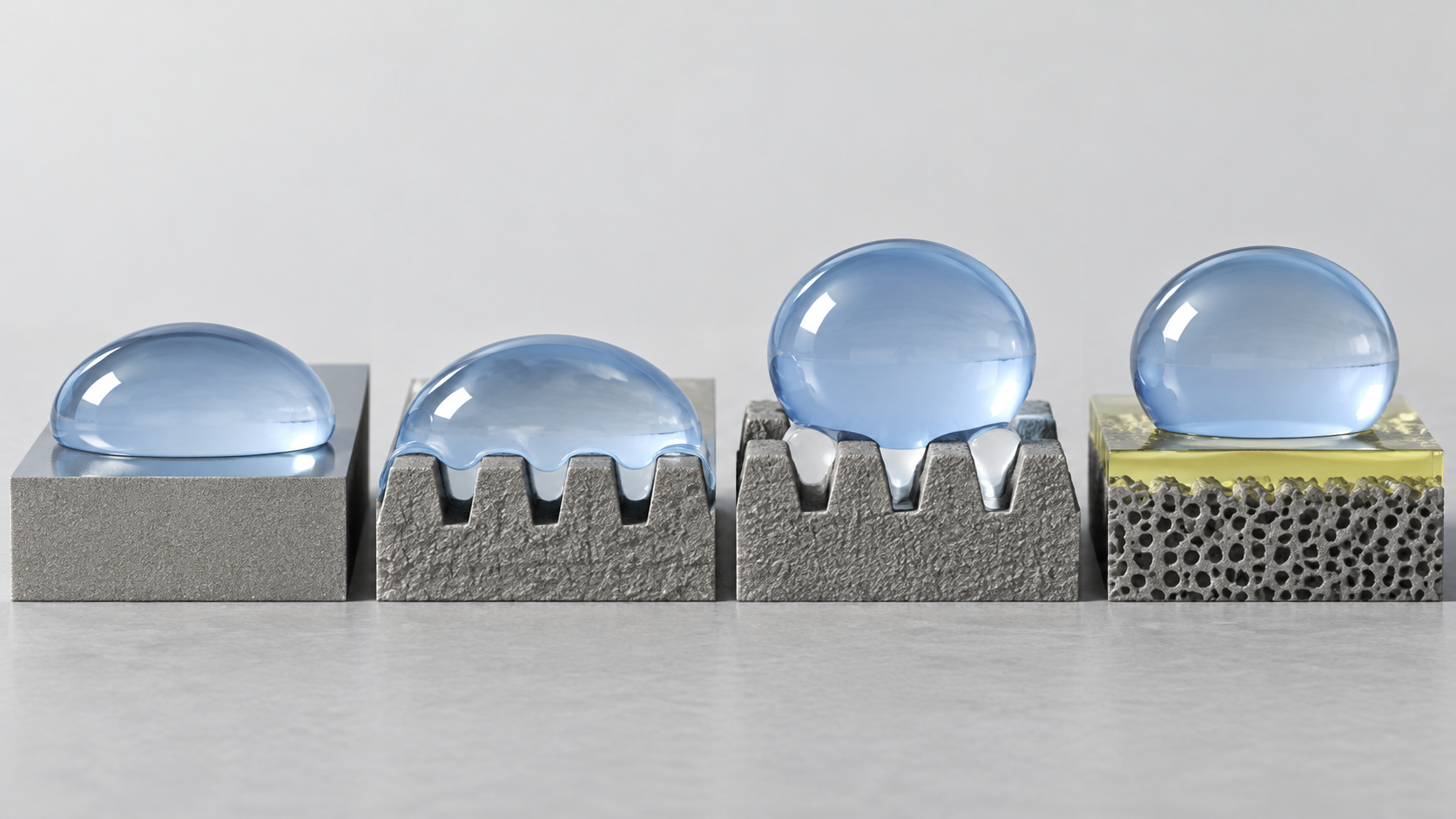
View the original SVG schematic and exact annotations
For lotus-inspired surfaces with fine texture, Wong et al. list these problems: limited repellency to oils with large contact angle hysteresis, failure under pressure, failure on physical damage, inability to self-heal, and high production costSourced [Source 6]. The SLIPS of Section 4 were proposed as a design that answers these.
In the development lab, the static contact angle (one number) tends to be reported first. But whether water rolls or sticks is decided by the difference between the advancing and receding angles (the hysteresis). Even with the same static contact angle, a surface with a low receding angle will not move a drop when tilted (Section 3 gives numbers). A Cassie-Baxter state can collapse at once when liquid enters the texture (a move to the Wenzel state). Pressure and physical damage [Source 6], and condensation and frost [Source 9], can trigger it. It is advisable to read the static value as the “initial value”, and the dynamic value and the value after abrasion as the “practical value” (Commentary).
3. Our calculation: solid fraction, and the tilt angle at which a drop rolls off
(1) The smaller the solid fraction f, the larger the apparent contact angle
Taking the contact angle θ on a smooth surface as 110°, we use the Cassie-Baxter equation cosθ* = f(cosθ + 1) – 1 to calculate the apparent contact angle θ* for each solid fraction fOur calculation. The equation was checked in an open-access paper [Source 23] as the one that gives the apparent contact angle of a Cassie-Baxter state (air retained).
- f = 0.05: about 165.3° / f = 0.1: about 159.1° / f = 0.2: about 150.3° / f = 0.3: about 143.4° / f = 0.5: about 132.1°
- That is, even for a smooth surface with θ = 110°, if the solid–liquid contact area fraction can be kept to about 0.2 or less, the calculation puts the apparent contact angle above 150°
Assumptions and limits: the equation assumes a full Cassie-Baxter state that retains air, and fails if liquid enters the texture (the Wenzel state). The value f is set by the geometry of the texture and is hard to estimate by measurement. And a large apparent contact angle is a different property from a drop that rolls (next calculation).
(2) With the same contact angle, a drop will not roll off if the hysteresis is large
The condition for a drop to start moving on a tilted surface is expressed by the Furmidge equation, mg sinα = γ w (cosθr – cosθa) (m: mass of the drop, γ: surface tension, w: width of the drop, θa: advancing angle, θr: receding angle)Sourced [Sources 3, 24]. In practice a factor k (set by the shape of the contact line, near 1) is added, as has been pointed out [Source 4].
Using this, for a 10 μL (10 mg) water drop, an advancing angle of 155°, a water surface tension of 72 mN/m and k = 1, we calculate the roll-off angle as the receding angle changesOur calculation. For the width of the drop’s base we used about 1.13 mm, obtained from a spherical cap with a 155° contact angle.
- Receding angle 150° (hysteresis 5°): roll-off angle about 1.9°
- Receding angle 145° (hysteresis 10°): roll-off angle about 4.2°
- Receding angle 125° (hysteresis 30°): roll-off angle about 16.0°
Assumptions and limits: this is an approximation with a spherical-cap drop and k = 1, and it need not agree with measured roll-off angles. The value changes with drop volume and width. Even so, it is certain that with the same static contact angle of 155°, once the receding angle falls to 125° the roll-off angle exceeds 10° and the surface no longer meets the “roll-off angle below 10°” guide [Source 5].
4. Liquid-infused surfaces (SLIPS) — sliding on liquid instead of air
In 2011 Wong et al. reported SLIPS (slippery liquid-infused porous surfaces), inspired by the Nepenthes pitcher plant. A nano/microstructured substrate locks in place an infused lubricating fluid, forming a stable, defect-free, inert “slippery” interface — a concept different from the lotus effectSourced [Source 6].
- They repel simple and complex liquids — water, hydrocarbons, crude oil, blood — with contact angle hysteresis below 2.5°
- After physical damage, liquid repellency is restored within 0.1–1 s (lubricant flows in and fills the damage)
- They resist ice adhesion and function at pressures up to about 680 atm
- The properties are insensitive to the geometry of the substrate, so the approach applies to various low-surface-energy structured materials, such as porous Teflon membranes
All Sourced (reported by Wong et al. [Source 6], under the authors’ conditions).
By using a liquid in place of air, SLIPS answers the problems of pressure, damage and contact angle hysteresis [Source 6]. But a liquid can flow out, be carried away, or evaporate. In repeated ice-and-release tests, Golovin et al. report that SLIPS-based surfaces using costly fluorinated lubricants saw ice adhesion strength rise about tenfold after just a few icing/deicing cycles. They also point out that the lubricant may be carried off by water droplets, frost or iceSourced [Source 9].
From a materials standpoint, the design of SLIPS is a combination of the chemistry of the lubricant (surface tension, viscosity, affinity for the substrate) and the force with which the structure retains it. In practice, life has to be designed including replenishment and renewal of the lubricant, and the initial performance in a paper (speed of recovery, hysteresis) does not tell the life (Commentary).
5. Anti-icing — reading ice adhesion strength
(1) What is measured — ice adhesion strength, and its relation to water wettability
In designing anti-icing surfaces we separate “ice does not form” from “ice that has formed comes away easily”. Golovin et al. define as “icephobic” a surface with an ice adhesion strength τice below 100 kPa, and state that passive removal of ice, for example from aircraft wings or power lines, needs below 20 kPaSourced [Source 9].
Meuler et al. tested bare steel and 21 coatings (about 200–300 nm thick) and showed that ice adhesion strength correlates strongly with the practical work of adhesion needed to remove a water drop (1 + cosθrec, where θrec is the receding angle). Materials containing fluorodecyl POSS cut ice adhesion strength by as much as a factor of 4.2. They argue that any further appreciable reduction will need textured surfaces, because no known material on a smooth surface has a receding angle significantly above those reportedSourced [Source 8].
Golovin et al. report that by tuning the cross-link density of elastomeric coatings and enabling interfacial slippage, irrespective of material chemistry, ice adhesion strength can be brought below 0.2 kPa. They also made coatings that keep below 10 kPa after severe abrasion, acid/base exposure, 100 icing/deicing cycles, thermal cycling, accelerated corrosion and several months of exposure to Michigan wintery conditionsSourced [Source 9]. The same paper states that the variation in ice adhesion across the elastomers tested was dominated by cross-link density, not by surface energy.
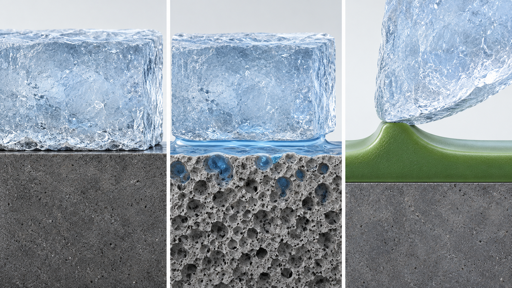
View the original SVG schematic and exact annotations
(2) When superhydrophobicity does not mean anti-icing
The review by Kreder et al. notes that superhydrophobic surfaces with fine texture have been shown to prevent ice accumulation under certain conditions, but the same texture is detrimental in other environments, and that a surface repelling ice in all scenarios has not been foundSourced [Source 7]. Golovin et al. also argue that superhydrophobic surfaces cannot keep their ice adhesion strength when condensing droplets or frost enter the texture [Source 9].
(3) Ice adhesion strength changes with how it is tested
The critical review by Rønneberg et al. states that experimentally obtained ice adhesion strengths are so far neither comparable nor transferable and are very sensitive to the experimental set-up and the type of ice. There are horizontal and vertical shear tests, centrifugal tests and tensile tests, and it proposes as a reference test a horizontal shear test with bulk-water iceSourced [Source 10]. It is also reported that, on the same aluminium substrate with a centrifugal test, ice adhesion strength differed about threefold with ice type (precipitation ice 0.78 MPa, in-cloud ice 0.53 MPa, bulk-water ice 0.28 MPa) [Source 11].
ISO/TS 19392-6:2026 specifies a centrifuge method of measuring the adhesion of artificial ice to coating systems for wind-turbine rotor blades. Its aim is reproducible results by defining ice types and removal test parameters; it does not give fixed test parameters for the variety of icing scenarios. A note states that ice adhesion can be measured on two principles, the centrifugal test and the shear testSourced [Source 29].
Consider shedding ice by gravity aloneOur calculation. For a plate of ice of thickness h on a vertical face, the shear stress it puts on the surface is roughly ρgh (ρ: density of ice, taken as about 917 kg/m3).
- h = 1 mm: about 9 Pa / h = 1 cm: about 90 Pa / h = 10 cm: about 900 Pa (about 0.9 kPa)
- By comparison, the 20 kPa that Golovin et al. give as the guide for passive removal, and the 100 kPa in the definition of “icephobic”, are 20 to over 100 times the shear stress from the weight of 10 cm of ice
- For an ice contact area of 0.01 m2 (10 cm × 10 cm), an adhesion strength of 100 kPa takes a shear force of about 1,000 N to remove the ice, 20 kPa about 200 N, and 10 kPa about 100 N (F = τ × A)
Assumptions and limits: this is a simple estimate that assumes a uniform ice plate on a vertical face, ignoring the shape of the ice, curvature, wind, vibration and gaps. For 10 cm of ice (about 0.9 kPa), the reported value below 0.2 kPa [Source 9] is lower than the load, but it does not reach 1 cm of ice (about 90 Pa). Even a coating that meets the 100 kPa definition of “icephobic” will not shed ice by its own weight alone. The design has to assume use together with wind, vibration, heating or mechanical removal (Commentary).
In evaluating anti-icing, do not take a large contact angle as the evidence. Ice adhesion strength correlates in part with the receding angle of water [Source 8], but for elastomers cross-link density and interfacial slip were dominant [Source 9]. So the height of water repellency and the strength with which ice comes away are not the same design axis. The items a materials engineer should check are (a) the type of ice and the test method (centrifugal or shear), (b) the value after how many icing/deicing cycles, (c) the value after abrasion, ultraviolet light and cleaning, (d) substrate and film thickness, and (e) the adhesion strength the application demands (how the ice will be removed) (Commentary).
6. Anti-fouling — kinds of dirt, and marine biofouling
“Anti-fouling” means different things for different kinds of dirt. Dirt dissolved in water or particles, oily dirt, and the attachment of organisms (biofouling) are evaluated separately (this article’s grouping).
| Kind of dirt | Property wanted of the surface | What was confirmed in primary sources |
|---|---|---|
| Aqueous dirt and particles (self-cleaning) | A small roll-off angle, so that drops roll and carry dirt away | When abrasion damages the roughness of a superhydrophobic surface, water begins to stick, and contamination by contact also shortens the useful life of self-cleaning. Photocatalysis and reduced electrical resistance have been proposed to stop dirt accumulating [14] |
| Oily dirt | Oil repellency (repelling liquids of lower surface tension than water) | Even superhydrophobic surfaces are wetted by surfactant solutions, alcohols and alkanes. Deng et al. reported a transparent “superamphiphobic” coating that is both superhydrophobic and superoleophobic, while non-fluorinated water repellents tend to lack oil repellence [5, 16] |
| Marine biofouling | Resisting attachment, or letting go at low shear even after attachment (barnacles, algae, biofilm) | See below (Callow and Callow [12]) |
The “What was confirmed” column is Sourced (Verho et al. [14], Deng et al. [5], Holmquist et al. [16], Callow and Callow [12]). The “Property wanted” column is commentary by this article.
(1) Marine biofouling — from biocides to coatings from which attached organisms release
According to the review by Callow and Callow (Nature Communications, 2011), biofouling of ship hulls imposes economic and environmental penalties on maritime industries. It cites powering penalties of up to 86% at cruising speed for a heavily fouled hull and 10–16% even for light fouling by diatom “slimes”. The main strategy is biocide-containing paints, but environmental concerns and legislation are driving science and technology towards non-biocidal solutions based solely on the physico-chemical properties of coatingsSourced [Source 12].
On the regulatory side, the International Maritime Organization (IMO)’s International Convention on the Control of Harmful Anti-fouling Systems on Ships (the AFS Convention) was adopted on 5 October 2001 and entered into force on 17 September 2008. It prohibits harmful organotins in anti-fouling paints on ships and sets up a mechanism to prevent the use of other harmful substances in anti-fouling systems. In 2021 the Marine Environment Protection Committee (MEPC) adopted amendments adding controls on the biocide cybutryne, which entered into force on 1 January 2023: from 1 January 2023 ships shall not apply or re-apply anti-fouling systems containing it, and shall remove it or apply a coating over it at the next scheduled renewal, no later than 60 months after the last applicationSourced [Source 13]. European biocide regulation is covered in our explainer on antimicrobial and anti-corrosion coatings.

Non-biocidal coatings from which attached organisms release (barnacles and other organisms come away at the low shear of a moving ship) do not prevent organisms from settling but weaken the attachment of those that do. According to Callow and Callow, most current commercial coatings of this kind are based on poly(dimethylsiloxane) elastomers (PDMS). They have low surface energy (about 22 mN/m) and low modulus, and release of hard fouling is proportional to (γE)1/2 (γ: surface energy, E: modulus). The drawbacks are that they are difficult to bond to a substrate without a tie coat, are less durable and more easily damaged, and often fail to release brown diatom slimes, which attach more strongly to hydrophobic surfaces. The technology is also most effective on high-activity, fast-moving (above 15 knots) vessels and is less suitable for vessels that spend long periods in port or cruise at lower speedsSourced [Source 12].
In the sea, a hydrophobic surface can instead be attached to more strongly by some organisms (diatoms) [Source 12]. A surface on which water drops roll on land is not necessarily one that stays clean underwater. Conversely, a design such as PDMS, with low modulus and low surface energy, which favours release of barnacles (hard fouling), is judged differently depending on the target organism and how the vessel is used (speed, time in port).
From a materials standpoint, the first things to check in an anti-fouling evaluation are (a) the target organism (hard fouling or slime), (b) where and for how long the test ran (sea area, season, days of immersion), (c) whether it was static or under shear, and (d) whether it contains a biocide. Material that discusses marine anti-fouling from land contact angle alone should be read with care (Commentary).
7. Durability — abrasion, ultraviolet light, condensation and frost
The greatest weakness of superhydrophobicity is durability. The review by Verho et al. (Adv. Mater. 2011) states that the microscopic roughness needed for superhydrophobicity is fragile, and that mechanical wear first shows as increased sticking of water and then as loss of non-wettability. Hierarchical roughness (nanoscale roughness protected by larger features), avoiding hydrophilic bulk materials and self-healing hydrophobic layers have been shown to raise wear resistance, but contamination from contact also shortens life, and the fragility of superhydrophobic surfaces currently limits their applicationsSourced [Source 14].
Tian, Verho and Ras state in a Science perspective (2016) that standardized wear and durability testing is needed to advance the best materialsSourced [Source 15]. In other words, the test method for abrasion resistance differs from paper to paper, and the numbers cannot be compared as they stand.
| Cause of degradation | Examples confirmed in primary sources | Examples of evaluation and standards (Section 10) |
|---|---|---|
| Abrasion and rubbing | The superamphiphobic coating of Deng et al. stayed superamphiphobic after its top layer was damaged by sand impingement (Science 2012) [5]. The coatings of Golovin et al. kept an ice adhesion strength below 10 kPa after severe abrasion [9] | JIS K 5600-5-9 (abrasive-wheel method), ASTM D4060 (Taber) |
| Ultraviolet light and outdoor exposure | Golovin et al. include several months of exposure to Michigan winter conditions [9]. Read outdoor durability separately as a real-environment result or an accelerated-test result | ISO 16474-3:2021, JIS K 5600-7-8, ASTM G154 |
| Repeated condensation, frost and icing | Golovin et al. report coatings holding below 10 kPa after 100 icing/deicing cycles; for SLIPS-based surfaces they report ice adhesion strength about tenfold after a few cycles [9] | ISO/TS 19392-6 is a method for measuring ice adhesion strength (the number of repetitions is outside its provisions) |
| Cleaning and chemicals | Golovin et al. also report values after exposure to acid and base [9]. A standard test for degradation by cleaning was not confirmed in this article | Could not be confirmed |
The “Examples confirmed” column is Sourced (statements in the abstract or body of each paper; conditions are each paper’s own). The standards column lists the numbers and titles confirmed in Section 10.
Manufacturers’ technical documents sometimes give a “contact angle after rubbing” in addition to the initial value (for an example, the stated values of a fluorinated anti-smudge coating agent are discussed in our explainer on nano-coatings and thin films). But how the rubbing was done (abrasive wheel or cloth, load, number of cycles) and how it corresponds to actual use cannot be known from the document. With superhydrophobic surfaces, even if the static contact angle is kept, once the receding angle falls (hysteresis rises), drops stop rolling (Section 3). After rubbing, it is a practical reading for a materials engineer to judge not only by the static contact angle but by the advancing and receding angles (or the roll-off angle) (Commentary).
8. Regulation of PFAS-based water repellents — proposal, adoption and application kept apart
(1) Why water repellents are an issue
According to the review by Holmquist et al. (Environment International, 2016), in textile durable water repellents (DWR) the phase-out of long-chain PFAS with perfluoroalkyl side chains and the substitution that followed have left both fluorinated and non-fluorinated water repellents on the market. The alternative DWRs fall into four groups: side-chain fluorinated polymers, silicones, hydrocarbons, and others (such as dendrimers and inorganic nanoparticles). The biggest difference is that the non-fluorinated alternatives lack oil repellence, and for all alternatives impurities and degradation products are diffusively emitted to the environment. In their hazard ranking the hydrocarbon-based DWR was the most benign, but the authors recommend choosing case by case, weighing the benefits of performance against the risksSourced [Source 16].
(2) Regulation differs by region and by stage
(3) EU: the PFHxA restriction is “adopted”, and application began on 10 October 2026
Commission Regulation (EU) 2024/2462 (dated 19 September 2024, published in the Official Journal on 20 September 2024) added entry 79 to Annex XVII of the REACH Regulation, restricting undecafluorohexanoic acid (PFHxA), its salts and PFHxA-related substances (substances considered, from their molecular structure, able to degrade or transform to PFHxA)Sourced [Source 17]. The ECHA registry of restriction intentions likewise gives the status as “Commission decided”, with the adopted restriction being Regulation 2024/2462 (Annex XVII entry 79) [Source 20].
| Date from which it applies (as written) | What is covered (as written) | Concentration limit (in homogeneous material) |
|---|---|---|
| From 10 October 2026 | (a) textiles, leather, furs and hides in clothing and related accessories for the general public, (b) footwear for the general public, (c) paper and cardboard used as food contact materials, (d) mixtures for the general public, (e) cosmetic products | 25 ppb for the sum of PFHxA and its salts; 1,000 ppb for the sum of PFHxA-related substances |
| From 10 October 2027 | Other textiles, leather, furs and hides for the general public (carpets, curtains, upholstery and so on) | Same as above |
| 10 April 2026 / 10 October 2029 | Firefighting foams (for training and testing, and for public fire services: 10 April 2026; civil aviation: 10 October 2029) | Same as above |
| Exemptions (as written) | Personal protective equipment (part of risk category III), medical devices and in vitro diagnostic devices, construction textiles; articles and mixtures placed on the market before each date | – |
All Sourced (the Annex of Commission Regulation (EU) 2024/2462 [Source 17]). The regulation entered into force on the twentieth day after publication. The checking date of this article is the same as the date from which the restriction on clothing and the like applies, 10 October 2026, and updates to guidance or interpretation after that date were not checked.
The recitals of the regulation state that PFHxA-related substances are used in large quantities in textiles, paper and cardboard for food contact, and firefighting foams; that the Commission confined the restriction to uses for which RAC concluded that risk management measures to minimise emissions cannot be implemented; and that outdoor clothing such as rain jackets is given as an example of what is covered. For general-public textiles other than clothing (carpets, curtains, upholstery and similar), they further state that alternatives for water-repellent properties appear to be available and that it has not been well established that the lack of oil and stain repellent properties would lead to functional losses with significant negative impactsSourced [Source 17].
The concentrations in the text are mass concentrations in homogeneous material (ppb)Our calculation. Taking 1 ppb as 1 µg/kg:
- 25 ppb (sum of PFHxA and its salts): 25 µg/kg = 0.025 mg/kg. In 1 kg of fabric, 25 µg in total
- 1,000 ppb (sum of PFHxA-related substances): 1,000 µg/kg = 1 mg/kg. In 1 kg of fabric, 1 mg in total
Assumptions and limits: these are concentration limits, not an allowable amount per product. How “homogeneous material” is to be understood and which analytical method is used are not settled by the text alone and were not checked here.
(4) EU: the all-PFAS restriction proposal is “proposed, under evaluation”
The comprehensive PFAS restriction proposal prepared by authorities in Germany, Denmark, the Netherlands, Norway and Sweden was submitted to ECHA on 13 January 2023. The consultation ran from 22 March to 25 September 2023. According to ECHA, the Committee for Risk Assessment (RAC) adopted its final opinion on 2 March 2026, and the Committee for Socio-economic Analysis (SEAC) agreed its draft opinion on 10 March. In its publication of 26 March 2026 ECHA stated that both committees support “an EU-wide restriction, subject to specific derogations”, and a consultation on SEAC’s draft opinion ran until 25 May 2026. SEAC is expected to adopt its final opinion by the end of 2026, after which the Commission, based on the final opinions, will propose a restriction for discussion and vote in the REACH Committee (composed of Member States)Sourced / Not yet confirmed [Sources 18, 19]. ECHA’s PFAS page lists, dated 7 October 2026, the agenda for the November SEAC meeting [Source 19].
In other words, the restriction proposal is proposed and under evaluation; as law it has been neither adopted nor brought into application. The content of derogations by sector, and how the parts relevant to water repellents are treated, were not checked in this article (listed under what could not be confirmed).
(5) Japan: designation of individual substances under the Chemical Substances Control Law
According to the Ministry of the Environment, the cabinet decided on 16 April 2021 a cabinet order designating PFOA (used in water repellents and other products) or its salts as a Class I Specified Chemical Substance under the Chemical Substances Control Law. Thirteen kinds of products, including water repellents, were designated as products that may not be imported, and the date of enforcement was 22 October 2021Sourced [Source 21]. Then on 5 July 2024 the cabinet decided an order adding “branched isomers of PFOA or salts thereof” and “PFOA-related substances” as Class I Specified Chemical Substances. As products that may not be imported, 13 kinds including water repellents were designated for the former and 8 kinds including water repellents for the latter. The “Schedule” in the same announcement gives planned enforcement dates of 10 September 2024 (designation of branched isomers) and 10 January 2025 (designation of related substances, import-prohibited products and so on) [Source 22]. The official gazette showing actual enforcement was not checked in this article.
The EU PFHxA restriction defines its scope by structure — substances containing a perfluorohexyl group C6F13– or a perfluoropentyl group C5F11– — and extends to “related substances” that can degrade to PFHxA [Source 17]. The reasoning “it is short-chain (C6), so it is treated differently” does not hold under this restriction. On the other hand, as Holmquist et al. show, alternatives must be evaluated separately for water repellence and oil repellence [Source 16]. If only water repellence is wanted, hydrocarbon and silicone options are realistic; uses that need oil repellence and stain resistance (food contact, medical and protective uses and so on) are a different discussion.
What a materials engineer should check is (a) whether the structure of one’s own water repellent falls under the regulated structure (including C5 and C6 partial structures and polymer side chains), (b) whether the required function is water repellence only or includes oil repellence and stain resistance, (c) the stage of the regulation (adopted, or proposed and under evaluation) and the date of application, and (d) how content will be confirmed along the supply chain (analytical methods). Reading by stage and scope, rather than lumping everything under the word PFAS, is the starting point for design and procurement (Commentary).
9. Limits, and what could not be confirmed
(1) Conditions in the papers’ bodies
For Wong et al. (2011), Kreder et al. (2016), Quéré (2008), Furmidge (1962) and others, this article relied on the abstract or the publisher’s page. Details of test conditions, substrate and liquids are not given.
(2) Data on commercial water-repellent, anti-icing and anti-fouling products
Datasheets and field life of actual products are not covered here. Our explainer on nano-coatings and thin films has an example of how to read a manufacturer’s stated values for a water-repellent film.
(3) PFAS regulation in the United States and other regions
US federal and state rules (the TSCA reporting rule, state PFAS product laws and so on), China and other regions were not checked here. The details of the EU all-PFAS restriction proposal (derogations by sector, the parts relevant to water repellents), the outcome of the consultation ECHA published in June 2026 and the record of the SEAC meeting were also not read.
(4) Confirming enforcement in Japan
For the 2024–2025 designations under the Chemical Substances Control Law, the planned enforcement dates in the Ministry of the Environment’s announcement at the time of the cabinet decision are given. Actual enforcement was not confirmed in the official gazette or similar.
(5) Standards
The texts of ISO, JIS and ASTM standards were not checked. An ISO standard for abrasion resistance, JIS and ASTM standards for ice adhesion strength, and a JIS for roll-off angle and dynamic contact angle could not be confirmed. No corresponding IEC or IEEE standard was confirmed either.
(6) Items not covered
Anti-fogging, evaluation of oil repellence (contact angles of oils), self-cleaning by photocatalysis, and the effects of biocide-containing paints and details of their regulation are not covered. Photocatalysis is in our explainer on titanium dioxide and photocatalysis, and biocide regulation in our explainer on antimicrobial and anti-corrosion coatings.
- Superhydrophobicity is defined by both a contact angle above 150° and a roll-off angle below 10°. With the same static contact angle, a drop will not leave a surface whose receding angle is lowSourced / Our calculation
- SLIPS slides drops on a lubricant, but the lubricant is consumed. Read anti-icing by ice adhesion strength and repeated-use life, not by contact angle, and compare only with the type of ice and test method matchedSourced
- Anti-fouling is a different design for each kind of dirt. At sea, some organisms attach more strongly to hydrophobic surfaces, so water repellency and anti-fouling are not the sameSourced
- Regulation of PFAS water repellents differs by region and by stage. The EU PFHxA restriction is adopted and began to apply on 10 October 2026, the all-PFAS restriction proposal is proposed and under evaluation, and Japan designates individual substances under its Chemical Substances Control LawSourced / Not yet confirmed
10. How to read evaluations and standards
What is measured in this field is contact angle (static, advancing and receding), roll-off angle, ice adhesion strength, the degree and strength of biofouling, and performance after abrasion and ultraviolet exposure. The methods include optical measurement of a drop’s angle (contact angle, roll-off angle), measuring the force to remove an ice sample (centrifugal or shear), immersion tests in the sea to see attachment, and accelerated tests of rubbing and light. What standards define is the method of each test; they do not give pass criteria or product performance for “superhydrophobic”, “anti-icing” or “anti-fouling”.
| Item | ISO | IEC / IEEE | JIS | ASTM | What changes the value with test conditions |
|---|---|---|---|---|---|
| Static contact angle, surface free energySourced | ISO 19403-1:2022 (vocabulary and general principles of wettability); ISO 19403-2:2024 (surface free energy of solid surfaces by contact-angle measurement) | Could not be confirmed | JIS R 3257 (wettability test method for substrate glass surfaces). Correspondence with ISO 19403 not confirmed | D7334 (practice for surface wettability of coatings, substrates and pigments by advancing contact angle measurement) | Drop volume, time since placing, temperature and humidity, surface contamination, the liquid |
| Dynamic contact angle (advancing and receding)Sourced | ISO 19403-6:2024 (advancing and receding angles by changing the volume of a drop) | Could not be confirmed | Could not be confirmed | Could not be confirmed (D7334 is stated in a paper to concern the advancing angle) | Speed of volume change, needle position, drop volume |
| Roll-off angleSourced | ISO 19403-7:2024 (dynamic contact angles and roll-off angle on a tilt stage; the 2017 edition is withdrawn) | Could not be confirmed | Could not be confirmed | Could not be confirmed | Drop volume, tilting speed, the definition of advancing and receding angles |
| Ice adhesion strengthSourced | ISO/TS 19392-6:2026 (ice adhesion by centrifuge for wind-turbine rotor blade coating systems; notes the shear test as another principle) | Could not be confirmed | Could not be confirmed | Could not be confirmed | Type and size of ice, centrifugal or shear, temperature, number of icing/deicing cycles [10, 11] |
| Marine biofoulingSourced | ISO 15181-1:2007 (general method for extracting biocides from anti-fouling paint films into artificial seawater; it supports measuring release rate and does not directly measure resistance to fouling) | Could not be confirmed | Could not be confirmed | D3623 (testing anti-fouling panels in shallow submergence), D4939 (subjecting marine anti-fouling coating to biofouling and fluid shear forces in natural seawater), D5618 (barnacle adhesion strength in shear, as stated in a paper; title not checked) | Sea area, season, immersion period, target organism |
| Abrasion resistanceSourced | Could not be confirmed | Could not be confirmed | JIS K 5600-5-9 (general test methods for paints, mechanical properties of film, abrasion resistance by the abrasive-wheel method) | D4060 (abrasion resistance of organic coatings by the Taber abraser) | Type of wheel, load, number of cycles. Standardisation said to be needed for superhydrophobic surfaces [15] |
| Accelerated weathering (ultraviolet)Sourced | ISO 16474-3:2021 (paints; exposure to fluorescent UV lamps, heat and water) | Could not be confirmed | JIS K 5600-7-8 (general test methods for paints, long-term durability of film, accelerated weathering by the fluorescent UV lamp method) | G154 (stated in a paper as accelerated weathering in a UV chamber; title not checked) | Type of lamp, temperature, presence of condensation or water, time, correlation with outdoors |
Numbers and titles of ISO standards were checked on the official ISO pages and those of JIS on the JIS search of the Japanese Industrial Standards Committee (JISC); JIS titles are our translation of the Japanese titles. For ASTM standards, the ASTM website was not opened; numbers and titles were checked only through statements in peer-reviewed papers and their reference lists. The ASTM column gives no test content, conditions or acceptance criteria. The arrangement of the table is Our calculation.
Where each standard sits — international, national, trade body
- The ISO 19403 series (wettability of paints and varnishes) is international, with vocabulary (Part 1), surface free energy (Part 2), dynamic contact angle (Part 6) and roll-off angle (Part 7) as separate standards [Sources 25-28]. Part 1 (2022), Part 2 (2024), Part 6 (2024) and Part 7 (2024) are the current editions, revised after the 2017 editions were withdrawn. An older document citing “ISO 19403-7:2017” cites a withdrawn edition
- JIS is a national standard. JIS R 3257 for the wettability of glass was confirmed, but a JIS corresponding to ISO 19403 could not be confirmed in this article. The degree of agreement between JIS and ISO could not be confirmed, because the body of the JIS was not checked
- ASTM standards are trade-body standards issued by a US standards organisation and form a system separate from ISO and JIS. Even for “contact angle”, what differs is whether only the advancing angle, a static angle or a dynamic angle is covered
Cautions when reading
- A standard is a “test method” and does not guarantee a material’s performance. ISO 19403-7 sets how to measure a roll-off angle; a judgement such as “superhydrophobic if below N degrees” is not part of it (the definition varies between papers, and this article uses “below 10°” of Deng et al. as an example [5])
- Ice adhesion strength changes with the test method and the type of ice. ISO/TS 19392-6 is for wind-turbine blades and uses a centrifuge. A common standard that applies to aircraft, power lines or ships could not be confirmed in this article. Read values together with their conditions [10, 11]
- Read a manufacturer’s value together with the standard, edition and test conditions it followed. For values after abrasion or ultraviolet exposure in particular, check the wheel, load and cycles, and the lamp type and time
- Watch the gap between the range of a standard and real service conditions. How a short accelerated test in the laboratory corresponds to years outdoors or at sea cannot be known from a standard alone [15]
11. Glossary
- Contact angle
- The angle a drop makes on a solid: static, advancing or receding.
- Advancing / receding angle
- The angle on the side where liquid spreads / the side where it shrinks.
- Contact angle hysteresis
- The difference between advancing and receding angles; it governs whether a drop moves.
- Roll-off angle
- The tilt angle at which a drop begins to roll off a surface.
- Superhydrophobic
- A water contact angle above 150° and a roll-off angle below 10° (as used by Deng et al.).
- Wenzel / Cassie-Baxter state
- Liquid fills the texture to its bottom / air is kept between the features.
- SLIPS
- Slippery liquid-infused porous surfaces: a structure that locks in a lubricating liquid.
- Ice adhesion strength
- The force per unit area needed to remove ice from a surface (kPa, MPa).
- Icephobic
- Resisting ice; defined by Golovin et al. as ice adhesion strength below 100 kPa.
- Biofouling
- The attachment of organisms to submerged structures; on hulls it raises drag and fuel use.
- Fouling-release coating
- A coating that does not prevent attachment but lets attached organisms release at low shear.
- PFAS / PFHxA
- Per- and polyfluoroalkyl substances / perfluorohexanoic acid (six carbons).
12. References (primary sources)
- Quéré D. “Wetting and Roughness”, Annu. Rev. Mater. Res. 38, 71–99 (2008), DOI 10.1146/annurev.matsci.38.060407.132434 — doi.org/10.1146/annurev.matsci.38.060407.132434
- Cassie A. B. D., Baxter S. “Wettability of porous surfaces”, Trans. Faraday Soc. 40, 546–551 (1944), DOI 10.1039/TF9444000546 — doi.org/10.1039/tf9444000546
- Furmidge C. G. L. “Studies at phase interfaces. I. The sliding of liquid drops on solid surfaces and a theory for spray retention”, J. Colloid Sci. 17, 309–324 (1962), DOI 10.1016/0095-8522(62)90011-9 — doi.org/10.1016/0095-8522(62)90011-9
- Stern Y. et al. “Furmidge Equation Revisited”, Langmuir 41, 11785–11793 (2025), DOI 10.1021/acs.langmuir.5c01302 (open access) — doi.org/10.1021/acs.langmuir.5c01302
- Deng X. et al. “Candle Soot as a Template for a Transparent Robust Superamphiphobic Coating”, Science 335, 67–70 (2012), DOI 10.1126/science.1207115 — doi.org/10.1126/science.1207115
- Wong T.-S. et al. “Bioinspired self-repairing slippery surfaces with pressure-stable omniphobicity”, Nature 477, 443–447 (2011), DOI 10.1038/nature10447 — nature.com/articles/nature10447
- Kreder M. J. et al. “Design of anti-icing surfaces: smooth, textured or slippery?”, Nat. Rev. Mater. 1, 15003 (2016), DOI 10.1038/natrevmats.2015.3 — nature.com/articles/natrevmats20153
- Meuler A. J. et al. “Relationships between Water Wettability and Ice Adhesion”, ACS Appl. Mater. Interfaces 2, 3100–3110 (2010), DOI 10.1021/am1006035 — doi.org/10.1021/am1006035
- Golovin K. et al. “Designing durable icephobic surfaces”, Sci. Adv. 2, e1501496 (2016), DOI 10.1126/sciadv.1501496 (open access) — doi.org/10.1126/sciadv.1501496
- Rønneberg S., He J., Zhang Z. “The need for standards in low ice adhesion surface research: a critical review”, J. Adhes. Sci. Technol. 34, 319–347 (2020), DOI 10.1080/01694243.2019.1679523 — doi.org/10.1080/01694243.2019.1679523
- Rønneberg S., Laforte C., Volat C. et al. “The effect of ice type on ice adhesion”, AIP Adv. 9 (2019), DOI 10.1063/1.5086242 (open access) — doi.org/10.1063/1.5086242
- Callow J. A., Callow M. E. “Trends in the development of environmentally friendly fouling-resistant marine coatings”, Nat. Commun. 2, 244 (2011), DOI 10.1038/ncomms1251 — nature.com/articles/ncomms1251
- International Maritime Organization (IMO) “International Convention on the Control of Harmful Anti-fouling Systems on Ships” (page on the AFS Convention) — imo.org (AFS Convention)
- Verho T. et al. “Mechanically Durable Superhydrophobic Surfaces”, Adv. Mater. 23, 673–678 (2011), DOI 10.1002/adma.201003129 — doi.org/10.1002/adma.201003129
- Tian X., Verho T., Ras R. H. A. “Moving superhydrophobic surfaces toward real-world applications”, Science 352, 142–143 (2016), DOI 10.1126/science.aaf2073 — doi.org/10.1126/science.aaf2073
- Holmquist H. et al. “Properties, performance and associated hazards of state-of-the-art durable water repellent (DWR) chemistry for textile finishing”, Environ. Int. 91, 251–264 (2016), DOI 10.1016/j.envint.2016.02.035 — doi.org/10.1016/j.envint.2016.02.035
- European Commission “Commission Regulation (EU) 2024/2462 of 19 September 2024 amending Annex XVII to Regulation (EC) No 1907/2006 as regards undecafluorohexanoic acid (PFHxA), its salts and PFHxA-related substances”, OJ L 2024/2462, 20.9.2024 (Publications Office of the EU) — publications.europa.eu/resource/celex/32024R2462
- ECHA “ECHA supports PFAS restriction with targeted derogations”, 26 March 2026 (ECHA/NR/26/17) — echa.europa.eu/-/echa-supports-pfas-restriction-with-targeted-derogations
- ECHA “Per- and polyfluoroalkyl substances (PFAS)” hot-topic page (including the update dated 7 October 2026) — echa.europa.eu/hot-topics/perfluoroalkyl-chemicals-pfas
- ECHA “Registry of restriction intentions until outcome: undecafluorohexanoic acid (PFHxA), its salts and related substances” — echa.europa.eu/registry-of-restriction-intentions (PFHxA)
- Ministry of the Environment, Japan Press release on the cabinet decision of the order amending the enforcement order of the Chemical Substances Control Law, 16 April 2021 (PFOA; in Japanese) — env.go.jp/press/109478.html
- Ministry of the Environment, Japan Press release on the cabinet decision of the order amending the enforcement order of the Chemical Substances Control Law, 5 July 2024 (branched isomers and related substances of PFOA; in Japanese) — env.go.jp/press/press_03409.html
- Chen et al. “A bio-based superhydrophobic pit and fissure sealant for enhanced stability and anticaries application”, Mater. Today Bio 41, 103690 (2026), DOI 10.1016/j.mtbio.2026.103690 (used to check the statement of the Cassie-Baxter equation; open-access text) — doi.org/10.1016/j.mtbio.2026.103690
- Dong et al. “Recent Advances and Retrospective Review in Bioinspired Structures for Fog Water Collection”, Biomimetics 10, 791 (2025), DOI 10.3390/biomimetics10120791 (used to check the statement of the Furmidge equation; open access) — doi.org/10.3390/biomimetics10120791
- ISO “ISO 19403-1:2022 Paints and varnishes — Wettability — Part 1: Vocabulary and general principles” — iso.org/standard/81414.html
- ISO “ISO 19403-2:2024 Paints and varnishes — Wettability — Part 2: Determination of the surface free energy of solid surfaces by measuring the contact angle” — iso.org/standard/87262.html
- ISO “ISO 19403-6:2024 Paints and varnishes — Wettability — Part 6: Measurement of dynamic advancing and receding angle by changing the volume of a drop” — iso.org/standard/87266.html
- ISO “ISO 19403-7:2024 Paints and varnishes — Wettability — Part 7: Measurement of the dynamic contact angles and the roll-off angle on a tilt stage” — iso.org/standard/87267.html
- ISO “ISO/TS 19392-6:2026 Paints and varnishes — Coating systems for wind-turbine rotor blades — Part 6: Determination and evaluation of ice adhesion using centrifuge” — iso.org/standard/89845.html
- ISO “ISO 16474-3:2021 Paints and varnishes — Methods of exposure to laboratory light sources — Part 3: Fluorescent UV lamps” — iso.org/standard/76034.html
- ISO “ISO 15181-1:2007 Paints and varnishes — Determination of release rate of biocides from antifouling paints — Part 1: General method for extraction of biocides” — iso.org/standard/42867.html
- Japanese Industrial Standards Committee (JISC) JIS search, JIS R 3257 (Testing method of wettability of substrate glass surface; title in Japanese) — jisc.go.jp (R3257)
- Japanese Industrial Standards Committee (JISC) JIS search, JIS K 5600-5-9 (Testing methods for paints — Part 5: Mechanical property of film — Section 9: Abrasion resistance (abrasive wheel method); title in Japanese) — jisc.go.jp (K5600-5)
- Japanese Industrial Standards Committee (JISC) JIS search, JIS K 5600-7-8 (Testing methods for paints — Part 7: Long-term durability of film — Section 8: Accelerated weathering (fluorescent UV lamp method); title in Japanese) — jisc.go.jp (K5600-7)
- Publicly available papers used to confirm ASTM numbers and titles (the ASTM website was not consulted): D7334 in Pine et al., Heliyon 7, e06234 (2021), DOI 10.1016/j.heliyon.2021.e06234 / D4060 in Sun et al., Polymers 15, 127 (2022), DOI 10.3390/polym15010127 / D3623 in Santos et al., Sensors 22, 7074 (2022), DOI 10.3390/s22187074 / D4939 in Park et al., Sci. Rep. 13, 9276 (2023), DOI 10.1038/s41598-023-36549-8 / D5618 in Chungprempree et al., Polymers 13, 2242 (2021), DOI 10.3390/polym13142242 / G154 in Rizzo-Sierra et al., Polymers 17, 2849 (2025), DOI 10.3390/polym17212849 — doi.org/10.1016/j.heliyon.2021.e06234 (and others)
13. Claim-to-source audit
| Claim in the text | Basis | Class |
|---|---|---|
| Roughness strongly affects the apparent contact angle and hysteresis and gives rise to superhydrophobicity, superoleophobicity and interfacial slip | Abstract of Quéré (2008) Reference 1 https://doi.org/10.1146/annurev.matsci.38.060407.132434 | Sourced |
| The original paper on the wettability of porous surfaces (Cassie-Baxter) | Cassie and Baxter (1944) Reference 2 https://doi.org/10.1039/tf9444000546 | Sourced |
| The original paper on the equation for sliding drops (Furmidge), and the point about the factor k | Furmidge (1962) Reference 3 https://doi.org/10.1016/0095-8522(62)90011-9 Stern et al. (2025) Reference 4 https://doi.org/10.1021/acs.langmuir.5c01302 | Sourced |
| The criterion for superhydrophobicity (contact angle above 150°, roll-off angle below 10°), the superamphiphobic coating, and its staying superamphiphobic after sand impingement | Abstract of Deng et al. (2012) Reference 5 https://doi.org/10.1126/science.1207115 | Sourced |
| The idea of SLIPS, hysteresis below 2.5°, recovery in 0.1–1 s, about 680 atm, the problems of lotus-type surfaces | Abstract of Wong et al. (2011) Reference 6 https://www.nature.com/articles/nature10447 | Sourced |
| Superhydrophobic surfaces can help or hurt anti-icing depending on conditions, and no surface repels ice in every environment | Abstract of Kreder et al. (2016) Reference 7 https://www.nature.com/articles/natrevmats20153 | Sourced |
| Correlation of ice adhesion strength with the receding angle (1 + cosθrec), 21 coatings, up to 4.2 times lower, textured surfaces needed for further reduction | Abstract of Meuler et al. (2010) Reference 8 https://doi.org/10.1021/am1006035 | Sourced |
| The definition of icephobic (below 100 kPa), below 20 kPa for passive removal, below 0.2 kPa by cross-link density and interfacial slip, below 10 kPa after abrasion, acid/base, 100 icing/deicing cycles, thermal cycling, accelerated corrosion and a Michigan winter, about tenfold increase for SLIPS-based surfaces after a few cycles, lubricant carried off, and superhydrophobic surfaces failing with condensation and frost | Golovin et al. (2016) Reference 9 https://doi.org/10.1126/sciadv.1501496 | Sourced |
| Ice adhesion strengths that cannot be compared or transferred, the measurement methods, and the proposal of a horizontal shear test | Abstract of Rønneberg et al. (2020) Reference 10 https://doi.org/10.1080/01694243.2019.1679523 | Sourced |
| Ice adhesion strength by ice type (precipitation ice 0.78, in-cloud ice 0.53, bulk-water ice 0.28 MPa; aluminium substrate, centrifugal test) | Abstract of Rønneberg et al. (2019) Reference 11 https://doi.org/10.1063/1.5086242 | Sourced |
| The burden of biofouling (powering penalty up to 86%, diatom slimes 10–16%), biocide paints as the main strategy, non-biocidal approaches, fouling-release coatings (PDMS, about 22 mN/m, (γE)^1/2, drawbacks, above 15 knots) | Callow and Callow (2011) Reference 12 https://www.nature.com/articles/ncomms1251 | Sourced |
| The AFS Convention (adopted 2001, in force 17 September 2008, organotins, the cybutryne amendment and 1 January 2023, 60 months) | Official IMO page Reference 13 https://www.imo.org/en/about/Conventions/Pages/International-Convention-on-the-Control-of-Harmful-Anti-fouling-Systems-on-Ships-(AFS).aspx | Sourced |
| Degradation of superhydrophobicity by wear, hierarchical roughness, contamination from contact, the proposal of photocatalysis and the like, fragility of the surface | Abstract of Verho et al. (2011) Reference 14 https://doi.org/10.1002/adma.201003129 | Sourced |
| The statement that standardised wear and durability testing is needed | Abstract of Tian et al. (2016) Reference 15 https://doi.org/10.1126/science.aaf2073 | Sourced |
| The four chemistries of water repellents (side-chain fluorinated polymers, silicones, hydrocarbons, others), the lack of oil repellence of non-fluorinated ones, diffuse emissions, the hazard ranking, and the recommendation to choose by use | Abstract of Holmquist et al. (2016) Reference 16 https://doi.org/10.1016/j.envint.2016.02.035 | Sourced |
| The PFHxA restriction (Annex XVII entry 79): covered substances, concentrations (25 ppb / 1,000 ppb), the dates of 10 October 2026, 10 October 2027, 10 April 2026 and 10 October 2029, exemptions, the recitals, the date of the regulation (19 September 2024) and entry into force on the twentieth day | Commission Regulation (EU) 2024/2462 Reference 17 https://publications.europa.eu/resource/celex/32024R2462 | Sourced |
| The course of the all-PFAS restriction proposal (submission on 13 January 2023, RAC and SEAC on 2 and 10 March 2026, publication on 26 March, consultation to 25 May, SEAC final opinion expected by end of 2026, later steps) | ECHA Reference 18 https://echa.europa.eu/-/echa-supports-pfas-restriction-with-targeted-derogations Reference 19 https://echa.europa.eu/hot-topics/perfluoroalkyl-chemicals-pfas | Sourced / Not yet confirmed |
| That the status of the PFHxA restriction is “Commission decided” and the adopted restriction is Regulation 2024/2462 | The ECHA registry of restriction intentions Reference 20 https://echa.europa.eu/registry-of-restriction-intentions/-/dislist/details/0b0236e18323a25d | Sourced |
| Japan’s Chemical Substances Control Law: PFOA and salts (cabinet decision 16 April 2021, enforcement 22 October 2021, 13 kinds of import-prohibited products including water repellents); branched isomers and related substances (cabinet decision 5 July 2024, planned enforcement 10 September 2024 and 10 January 2025) | Announcements of the Ministry of the Environment Reference 21 https://www.env.go.jp/press/109478.html Reference 22 https://www.env.go.jp/press/press_03409.html | Sourced |
| The statements of the Cassie-Baxter and Furmidge equations | Open-access papers Reference 23 https://doi.org/10.1016/j.mtbio.2026.103690 Reference 24 https://doi.org/10.3390/biomimetics10120791 | Sourced |
| Numbers, titles, editions and scope of ISO 19403-1:2022, 19403-2:2024, 19403-6:2024, 19403-7:2024, ISO/TS 19392-6:2026, ISO 16474-3:2021 and ISO 15181-1:2007 | Official ISO pages Reference 25 https://www.iso.org/standard/81414.html Reference 26 https://www.iso.org/standard/87262.html Reference 27 https://www.iso.org/standard/87266.html Reference 28 https://www.iso.org/standard/87267.html Reference 29 https://www.iso.org/standard/89845.html Reference 30 https://www.iso.org/standard/76034.html Reference 31 https://www.iso.org/standard/42867.html | Sourced |
| Numbers and titles of JIS R 3257, K 5600-5-9 and K 5600-7-8 | JIS search of the Japanese Industrial Standards Committee (JISC) Reference 32 https://www.jisc.go.jp/app/jis/general/GnrJISNumberNameSearchList?show&jisStdNo=R3257 Reference 33 https://www.jisc.go.jp/app/jis/general/GnrJISNumberNameSearchList?show&jisStdNo=K5600-5 Reference 34 https://www.jisc.go.jp/app/jis/general/GnrJISNumberNameSearchList?show&jisStdNo=K5600-7 | Sourced |
| Numbers of ASTM D7334, D4060, D3623, D4939, D5618 and G154 and what papers say of them (the ASTM website was not consulted; checked through statements in peer-reviewed papers and their reference lists) | Open-access peer-reviewed papers Reference 35 https://doi.org/10.1016/j.heliyon.2021.e06234 (and others listed at the end of the references) | Sourced |
| Solid fraction and apparent contact angle (for θ = 110°, about 165.3 to 132.1° for f = 0.05 to 0.5), receding angle and roll-off angle (10 μL, advancing angle 155°, k = 1: about 1.9, 4.2 and 16.0°), the weight of ice ρgh (about 9, 90 and 900 Pa) and the force needed from adhesion strength, 25 ppb = 0.025 mg/kg, 1,000 ppb = 1 mg/kg | Our calculation. Illustrations that assume a Cassie-Baxter state, a spherical-cap drop with k = 1, and a uniform ice plate; not measured values | Our calculation |
| The conditions in the bodies of the papers by Wong, Kreder, Quéré and Furmidge; data on commercial products; PFAS regulation in the US and elsewhere; the individual content of the EU all-PFAS proposal; the official gazette showing actual enforcement in Japan; an ISO standard for abrasion resistance; JIS and ASTM standards for ice adhesion strength, roll-off angle and dynamic contact angle; corresponding IEC and IEEE standards | Could not be confirmed in the primary sources accessible within this article’s survey, so not stated | Commentary |
| The readings: “static value as initial value, dynamic and post-abrasion values as practical”, “the lubricant is a consumable part”, “choose anti-icing by adhesion strength and life”, “water repellent is a different design axis from anti-fouling”, “initial contact angle versus dynamic angle after rubbing”, “regulation by structure, alternatives by function”; the grouping in Figs. 2, 5 and 7 | This article’s own organisation and interpretation of published content. Not the views of any company or institution | Commentary |
| That Figs. 2 to 5 and 7 are explanatory drawings, not real observations or data, and that Figs. 1 and 6 are AI-generated images | This article’s note | Commentary |
Last updated 10 October 2026. Sources are limited to primary material (peer-reviewed papers, an EU regulation in the Official Journal, and pages of ECHA, the IMO, Japan’s Ministry of the Environment and standards bodies). Many papers were checked only to the extent of their abstracts, and the test conditions in the body were not checked for some of them. Because the article includes structural readings and materials-design interpretations, those are marked as Commentary and kept separate from sourced fact. PFAS regulation in the United States and elsewhere, the individual content of the EU all-PFAS proposal, the official gazette showing actual enforcement in Japan, and JIS and ASTM standards for ice adhesion strength could not be confirmed and are not stated here. The contact-angle, ice-adhesion and durability figures are laboratory results whose substrate, film thickness and test method differ from paper to paper, and cannot be generalised to production items or real service conditions. All figures are explanatory concept graphics. Figs. 2 to 5 and 7 are vector drawings; Figs. 1 and 6 are AI-generated images, and none of them shows a real micrograph, experimental data or physical product.