TECHNOLOGY EXPLAINER
Satellite Structures and Small Satellites
— Bus and payload, how CubeSats think, and what decides the frame's materials
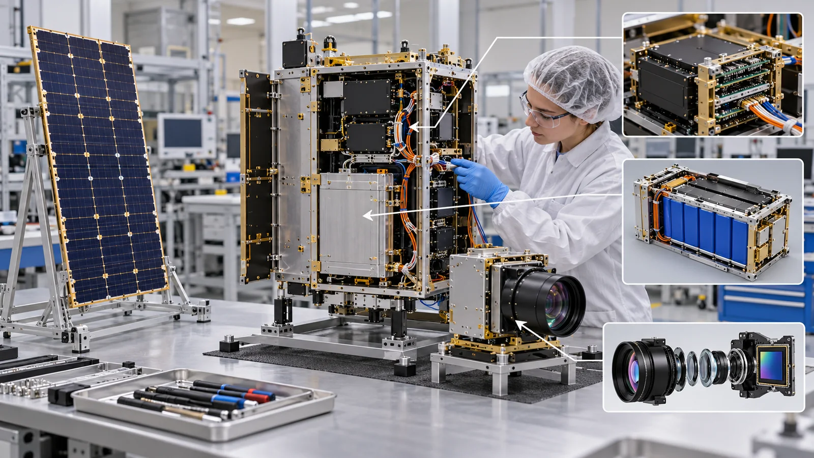
A satellite is a "box of precision instruments" that is shaken hard on top of a rocket and then has to endure vacuum, temperature swings and radiation. Its frame cannot simply be light: it must carry the launch loads, give heat a way out, shield the electronics from radiation and give off little gas, all at once. Written for materials engineers who know little about spaceflight, this article explains, with figures from public sources and a few small calculations, the habit of splitting a satellite into a "bus" (the base) and a "payload" (the mission equipment), the classes of orbit and mass, the rules of small satellites and CubeSats, and the frame materials (aluminum, composites, 3D printing).
- The short version / what to know first / where this fits in the series
- What a satellite is made of: bus and payload
- Classes of orbit and size: altitude and mass
- CubeSats: the idea of a standard box
- The first great test, launch: loads and vibration
- Frame materials: aluminum, sandwich panels, composites, 3D printing
- The frame is also a radiation shield
- Outgassing of structural materials and their pre-treatment
- Limits, and what could not be confirmed
- How to read the yardsticks and standards
- Glossary / References / Claim-to-source audit
Sourced = stated in published material (link given)
Our calculation = a value this article worked out from stated assumptions
Not yet confirmed = plans, drafts or targets that are not settled
Readings for the materials field are marked as commentary. Inference is shown in bold. Every analogy comes with its limit.
The mass classes and the CubeSat sizes and masses are values stated in NASA's report and in the specification. The names and boundaries of the classes differ between sources and change with editions (the CubeSat mass limits, too, have been revised). The radiation numbers are measurements and model values for one orbit (500 km altitude, 85 degrees inclination) and do not carry over to other orbits. The sandwich-panel comparison is an illustrative value we calculated. For standards we only checked titles, scope and status; because this field changes fast, they carry a checking date (17 October 2026).
1. The short version / what to know first / where this fits in the series
- A satellite is a "bus" plus a "payload". The bus is the base that keeps the satellite alive and moving (structure, power, communications, pointing control, thermal, propulsion, data handling); the payload is the mission equipment (cameras, relays and so on). This article's subject is the "structure" inside the bus and the materials behind it Sourced[Ref. 2]
- Small satellites are defined by mass classes and a standard box. NASA's report divides small satellites by mass (nano 1 to 10 kg, micro 10 to 100 kg, mini 100 to 180 kg and so on). A CubeSat is a standard box built on a 10 cm cube, 1U; the specification sets a maximum of 2 kg for 1U, aluminum alloy as the default frame material, and a TML of 1.0 % or less and CVCM of 0.1 % or less for materials Sourced[Ref. 1, 4]
- Frame materials are chosen by four things: loads, heat, radiation and gas. These are launch vibration, heat paths in vacuum, shielding for the electronics, and outgassing. For example, for a CubeSat with a 0.2 cm aluminum structure in low orbit, a reported estimate of the yearly radiation dose approaches the dose that commercial parts are said to tolerate (2 to 10 krad) Sourced[Ref. 3]
No prior knowledge is needed. Space terms (orbit, low orbit, outgassing and so on) are explained where they appear. An "orbit" is a state of "falling while moving sideways fast enough never to hit the ground". The "five enemies" of the space environment (vacuum, radiation, big temperature swings, atomic oxygen and UV, microgravity and debris) are collected in our explainer on the space environment and its effects on materials.
Reading our explainer on the space environment and its effects on materials first helps. Next come our explainer on spacecraft thermal control (how heat is shed), our explainer on CFRP and composites for space (carbon-fiber structures), our explainer on lightweight structural materials, and our explainer on additive manufacturing for space (3D printing). High-heat-resistant plastics such as PEEK are in our explainer on super engineering plastics for space, and how gas is released is in our explainer on polyimides for space.
2. What a satellite is made of: bus and payload
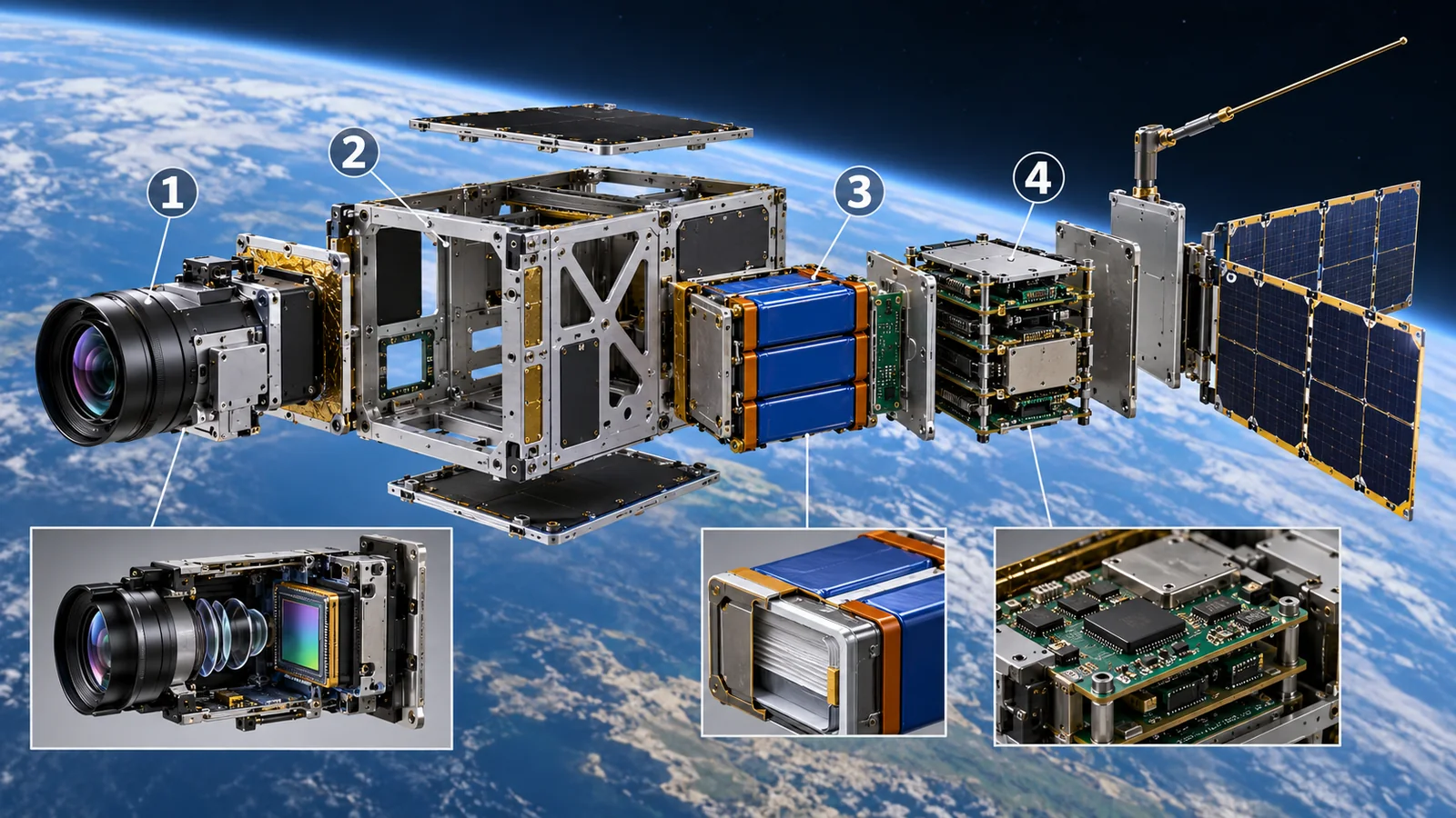
Think of a satellite as a vehicle. A bus carries passengers to their destination and takes care of driving, electricity and air conditioning. The passengers correspond to the observation or communication equipment the satellite carries, the payload. In a satellite, the part that plays the role of the vehicle body is called the bus. Where the analogy breaks down: a bus passenger just sits, but a satellite payload demands a great deal of power, heat control and pointing, and ends up dictating the bus design.
NASA's report on small-spacecraft technology organizes the technologies that make up a bus into chapters on power, propulsion, guidance, navigation and control (pointing control), structures, materials and mechanisms, thermal control, avionics (on-board electronics and data handling) and communications Sourced[Ref. 2].
View original SVG, values and sources
Original SVG reference: Concept diagram (vector drawing). A satellite split into the bus (seven subsystems) and the payload. The subsystem division follows the chapters of NASA's report, and the material examples are illustrative. That the payload's size and power set the bus design is our own commentary.
Each of the seven subsystems rests on materials. The structure uses aluminum alloys and composites; power uses solar-cell semiconductors and batteries; thermal control uses multilayer insulation and paints; communications uses antenna metals and dielectrics; and the electronics use boards and semiconductors. From the materials side, a satellite is materials that are light, strong, heat-resistant, electrically suitable and low in outgassing, packed into a small box (commentary). This article covers the "structure" that supports all the rest.
3. Classes of orbit and size: altitude and mass
Orbits: altitude changes the time per lap and the environment
According to ESA, low Earth orbit (LEO) extends to about 2,000 km, an upper limit set by the harsh environment of the Van Allen belts above it (regions of strong radiation). Satellites normally do not fly below 180 km because of the atmosphere. A LEO satellite moves at about 7.8 km per second relative to the Earth and completes a lap in about 90 minutes; the ISS circles the Earth about 16 times a day Sourced[Ref. 5].
Geostationary orbit (GEO) is above the equator at 35,786 km, where one lap takes 23 hours 56 minutes 4 seconds (a sidereal day), so the satellite appears to stand still from the ground. Its speed is about 3 km per second. Medium Earth orbit (MEO) covers the wide range from above the Van Allen belts in LEO up to GEO. Sun-synchronous orbit (SSO) is a kind of polar orbit that passes over the same place at the same local time each day; its altitude is usually 600 to 800 km Sourced[Ref. 5].
Take the Earth's gravitational parameter μ = 3.986 × 10⁵ km3/s2 and the Earth's radius as 6,371 km, and compute the circular-orbit period T = 2π√(a3/μ) (a is the orbit radius). At 400 km (a = 6,771 km), T ≈ 92.4 minutes and the speed √(μ/a) ≈ 7.67 km/s. At 800 km (a = 7,171 km), T ≈ 100.7 minutes and the speed ≈ 7.46 km/s. For geostationary orbit (a = 42,164 km), T ≈ 23.9 hours and the speed ≈ 3.07 km/s, in agreement with ESA's values (23 h 56 min, about 3 km/s) Our calculation. Assumptions and limits: a textbook calculation for a circular orbit at constant altitude, not real orbital elements.
Mass: small satellites are classed by weight
NASA's report takes 180 kg as the guide to the upper mass limit of a small satellite (it became a convenient benchmark because one slot of the ESPA ring, an adapter for secondary payloads, had a 180 kg allocation). The classes are: minisatellite 100 to 180 kg, microsatellite 10 to 100 kg, nanosatellite 1 to 10 kg, picosatellite 0.1 to 1 kg and femtosatellite 0.01 to 0.09 kg. The preface of the same report, however, describes the "mini-class" constellations that have grown since 2023 as 201 to 600 kg and a newer generation of small-satellite fleets as 600 to 1,200 kg Sourced[Ref. 1, 2]. In other words, the names and boundaries differ by source and by period.
NASA's report says that some of today's small satellites match full-size satellite buses in capability. But because the volume of dispensers and deployment rings is the constraint, structural parts often do double duty, handling thermal management, radiation shielding and pressure containment as well Sourced[Ref. 3]. A small satellite is less "small" than a satellite with tight limits on volume and mass that makes each part do many jobs (our reading).
4. CubeSats: the idea of a standard box
CubeSats are a family of small satellites with a standard size and shape, built on a 10 cm cube called one "U". The CubeSat Project started in 1999 as a collaboration between Prof. Puig-Suari at California Polytechnic State University, San Luis Obispo (Cal Poly), and Prof. Twiggs at Stanford University, with the aim of cutting cost and development time, widening access to space and sustaining frequent launches. The CubeSat Design Specification (CDS) sets the design requirements for 1U to 12U and the interface to the dispenser (deployer) Sourced[Ref. 4].
What does a standard box buy? Because dispensers are standardized too, the launch side can load a satellite without worrying about its contents, and the cost of launch procedures drops. We pick out the main CDS requirements (Rev. 14.1) with a materials engineer's eye Sourced[Ref. 4].
- Mass: 1U up to 2.00 kg, 2U 4.00 kg, 3U 6.00 kg, 6U 12.00 kg, 12U 24.00 kg (the table's "typical maximum"; it changes with the dispenser's capability).
- Materials: the structure should be an aluminum alloy; 7075, 6061, 6082, 5005 and 5052 are typically used. External aluminum surfaces that touch the dispenser rails must be hard-anodized to prevent cold welding.
- Outgassing: materials must have a TML of 1.0 % or less and a CVCM of 0.1 % or less, and the specification points to NASA's list of approved low-outgassing materials.
- Testing: random vibration to levels set by the launch provider; thermal-vacuum bakeout to drive out outgassing; shock testing is typically not required.
The CubeSat mass limits have changed with each revision. The CDS revision history records an acceptance-checklist mass limit for 1U being revised to "1.33 kg", whereas the Rev. 14.1 table says 2.00 kg Sourced[Ref. 4]. Always check the edition of the specification.
The CDS asks for an aluminum-alloy structure and even specifies anodizing. This lets a CubeSat leave a dispenser cleanly and avoids interference with other satellites. From the materials side, inside a standard box the freedom in frame material is small; the differences arise in internal parts, adhesives, insulation and coatings. And the CDS criterion for materials is TML (1.0 % or less), which does not remove water. That differs from the ECSS way of judging by RML, with water removed (our explainer on polyimides for space) (commentary).
5. The first great test, launch: loads and vibration
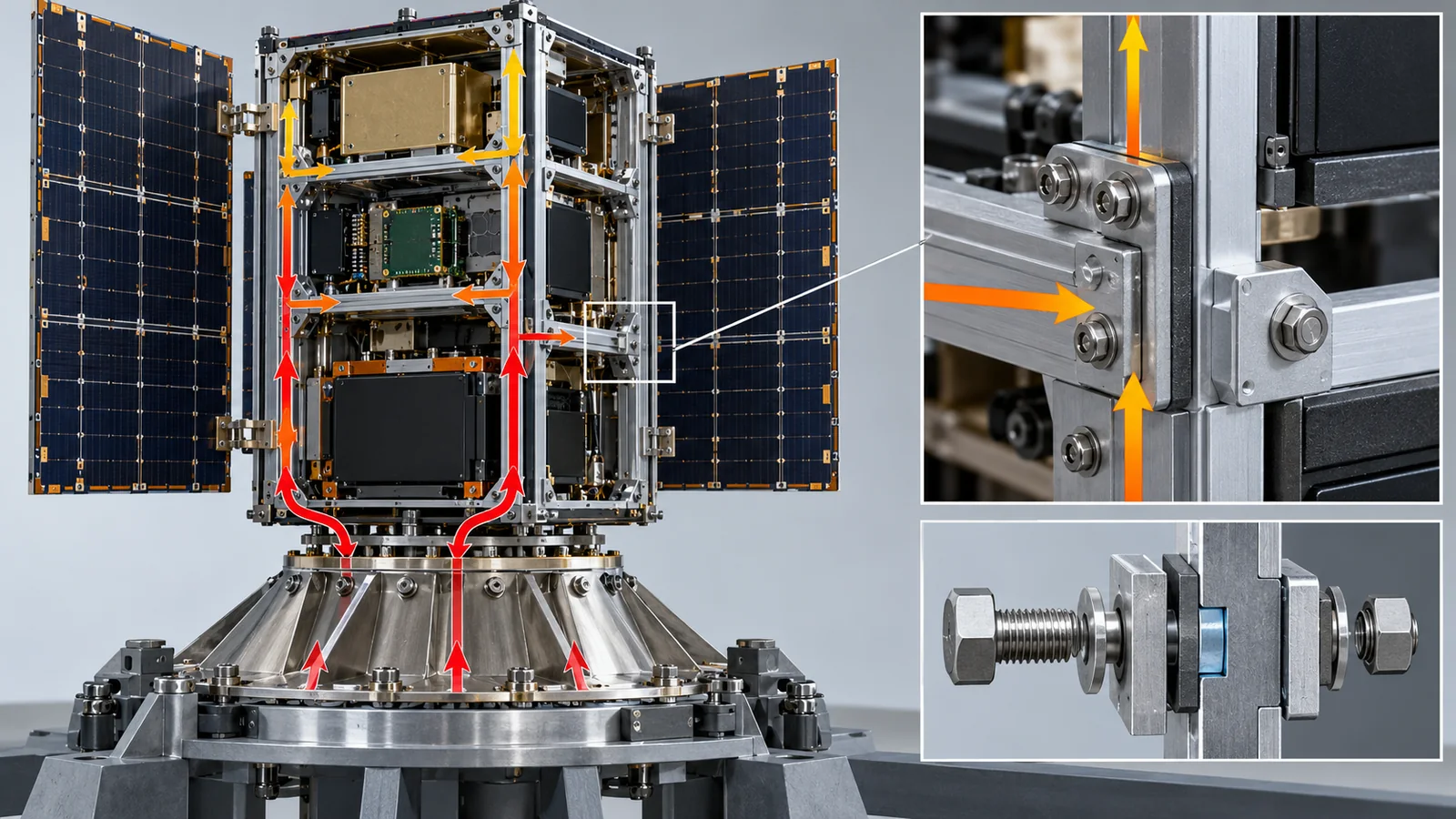
Almost the first ordeal a satellite frame meets is launch. Rocket engines and airflow shake the satellite hard. The frame must carry these loads without breaking and must not pass too much of them on to the parts inside.
View original SVG, values and sources
Original SVG reference: Concept diagram (vector drawing). How launch vibration travels from the rocket to the dispenser and the satellite frame, with a summary of the rules in the specification and the report. A concept diagram for a rail-type CubeSat dispenser, not the structure of any specific dispenser.
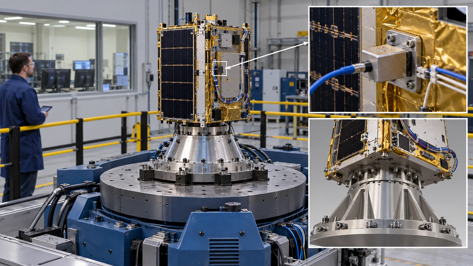
NASA's report says that NASA's CubeSat call (CSLI) requires a satellite to withstand the vibration environment of GEVS (the General Environmental Verification Standard), about 10 G rms for 2 minutes. The vibration conditions of an actual launch are given by the launch provider. With rail-type dispensers there is a thin gap between the satellite frame and the dispenser rails, and the report also says that rattling (chatter) in that gap raises the loads in testing and launch Sourced[Ref. 3]. GEVS is a standard for environmental testing for NASA Goddard flight projects; Version B (2021) is active, but NASA's page shows it is neither a NASA mandatory standard nor a NASA endorsed standard Sourced[Ref. 6].
An example of design conditions: a 2U CubeSat in one paper
Rinaldi and colleagues give the design conditions for a 2U CubeSat structure to be launched on Soyuz. Based on the launch vehicle user's manual, they set lower limits on the first five natural frequencies of 50, 51, 70, 90 and 110 Hz, and multiplied quasi-static loads by a model-uncertainty factor of 1.1 and a design-and-environment factor of 1.25 (1.375 in all). The resulting loads were ±4.675 g laterally and -7.9 g/+4.95 g longitudinally, with an equivalent stress limit below 45.45 MPa Sourced[Ref. 14]. These are the conditions of one design in one paper and do not apply to other launchers or satellites. They do show, though, that in frame design keeping the natural frequencies away from the rocket's vibration frequencies matters about as much as the size of the load (commentary).
6. Frame materials: aluminum, sandwich panels, composites, 3D printing
NASA's report describes choosing the frame material of a small satellite as a problem of satisfying both physical properties (density, thermal expansion, radiation resistance) and mechanical properties (modulus, strength, toughness). A typical satellite structure mixes metals and non-metals: metals are homogeneous and isotropic, while composites are inhomogeneous and anisotropic but can have properties tailored to load paths. The operating environment governs the choice, with adequate margin for launch and operating loads, and thermal balance and thermal-stress management, as well as the payload's sensitivity (to outgassing and thermal displacement), must be considered too Sourced[Ref. 3].
Primary and secondary structures
NASA's report divides a satellite's structure into primary and secondary structures. If the primary structure (frame, chassis) fails, the mission usually fails. Secondary structures (solar panels, thermal blankets, subsystems) attach to the primary structure, are self-supporting and carry few critical loads. In somewhat larger small satellites such as the ESPA class, assemblies machined from aluminum alloy remain the mainstream for primary structure. CubeSat frames are mostly machined from 6061 or 7075 aluminum alloy Sourced[Ref. 3].
Sandwich panels: a thin skin around a thick core
Why can a panel be light and yet hard to bend? Because bending strength depends on how far the material sits from the middle. It is like a ruler, which bends less when stood on edge than when laid flat. A sandwich panel bonds thin skins to both faces of a light core (honeycomb, in the shape of a beehive), moving the skins away from the center. NASA's report also lists aluminum honeycomb sandwich panels among the well-proven lightweighting methods Sourced[Ref. 3].
The bending stiffness D of a solid plate is D = E t3/12 (E: Young's modulus, t: thickness), and that of a sandwich is D ≈ E × tf × d2/2 (tf: skin thickness, d: distance between the centers of the two skins). With 0.5 mm skins and a 20 mm core, d = 20.5 mm and D ≈ 70 × 109 × 0.5 × 10-3 × (20.5 × 10-3)2/2 ≈ 7,350 N·m. The mass is 2 × 0.5 mm × 2,700 + 20 mm × 50 = 3.7 kg/m2. A solid aluminum plate of the same mass (3.7 kg/m2) is about 1.4 mm thick and has D ≈ 15 N·m, so the sandwich is about 490 times stiffer. Even against a 3 mm solid aluminum plate (8.1 kg/m2, D ≈ 158 N·m), it is about 47 times stiffer at about 46 % of the mass Our calculation.
Assumptions and limits: shear deformation of the core, wrinkling of the skins (local buckling), loads at bolted points, bond strength and thermal stress are ignored. In a real panel, reinforcement around inserts and the quality of the bond layer govern the design.
A sandwich is made of three materials: skins, bond layers and core. NASA's report says honeycomb panels are not isotropic: they do not show the same stiffness in all directions Sourced[Ref. 3]. As Chapter 8 shows, the bond layer can be a main source of outgassing, and heat flows poorly through the core (the heat paths are only the skins and the core walls), so it matters for thermal design too (commentary). In effect, choosing the "material" of a sandwich means choosing the adhesive and the control of the bonding process.
Composites and 3D printing
As for composites, the DiskSat that the Aerospace Corporation is developing (a disk 1 m in diameter and 2.5 cm thick) has a graphite (carbon-fiber) epoxy sandwich structure with a structural mass below 3 kg/m2. NASA's report says its first launch took place in December 2025, the dispenser worked as designed, communications with the ground succeeded, and it is now in checkout and initialization Sourced[Ref. 3]. The in-orbit record of carbon-fiber PEEK composites is covered in our explainer on super engineering plastics for space, which treats the thermal-expansion measurement on Ten-Koh [Ref. 15].
3D printing was once used only for secondary structures, but NASA's report says it is beginning to be used for primary structures in CubeSat and even smaller PocketQube-class spacecraft. KickSat-2 (a device that released chip-sized satellites) flew with a structure made entirely of ABS plastic, because the single-use design, short mission, and intricate frame made a conventionally machined deployer prohibitive in mass and cost Sourced[Ref. 3]. Additive manufacturing is covered in detail in our explainer on additive manufacturing for space.
7. The frame is also a radiation shield
The thickness of the frame has another job: it is a shield that protects electronic parts from radiation. NASA's report calls shielding a cost-effective way to cut the risk of failure of electronics from total ionizing dose (TID) and internal charging, and says that historically the cost of adding shielding has averaged below 10 % of a spacecraft's total cost. The simplest method is shielding by the mass already there, such as the outer skin and chassis (inherent mass shielding) Sourced[Ref. 3].
Shields-1 was an experiment in low orbit that measured the effect of shielding made of aluminum and of "high-Z" (high atomic number) laminates. As the figure shows, the model value for 0.198 cm of aluminum (areal density 0.535 g/cm2) is 1,383 rad(Si) per year, whereas at 1.26 g/cm2 (0.465 cm thick) the measurement is 90.9 rad(Si) per year Sourced[Ref. 3]. Raising the areal density by about 2.4 times (1.26 ÷ 0.535) lowers the dose to about 1/15 (1,383 ÷ 90.9 ≈ 15) Our calculation. Beyond about 1.3 g/cm2, the values tend to level off near 75 to 90 rad per year. Inference: the reason for the leveling off (secondary particles, more energetic particles, the measurement floor and so on) cannot be told from the report's table alone. A 3.02 g/cm2 high-Z electronics box (vault) gave 75.6 rad(Si) per year, which NASA's report states as a reduction of more than 18 times against modeled 0.20 cm aluminum.
NASA's report gives the radiation hardness of commercial electronic parts for the ISS orbit as in the range 2 to 10 krad. The same report estimates, for a 0.20 cm aluminum structure in a circular orbit at 500 km and 85 degrees inclination, a yearly trapped-particle dose of 1,383 rad and about 750 rad from solar particle events, a total of 2,133 rad. Dividing a tolerance of 2 to 10 krad by that gives 2,000 ÷ 2,133 ≈ 0.9 years to 10,000 ÷ 2,133 ≈ 4.7 years. The report says that once the uncertainty of the trapped-particle model (a factor of two or more) is added, the total approaches the lifetime of many commercial parts SourcedOur calculation. Assumptions and limits: a rough guide from dividing a dose by years, not a test result for any part.
NASA's report says that the conventional shield is thicker structural aluminum, but that aluminum is a material optimized in mass for structure and surface charging, not for shielding protons, ions or electrons. It adds that research on materials optimized for both structure and shielding continues in NASA's small-business research program Sourced[Ref. 3]. From the materials side, "where the structural mass is placed" is itself the shielding design. Holes and gaps in the frame also deserve attention ("shielding per unit solid angle", for particles arriving from all directions) (commentary).
8. Outgassing of structural materials and their pre-treatment
Frame materials are also judged by the gas they release in vacuum. The CubeSat specification sets a TML of 1.0 % or less and a CVCM of 0.1 % or less for materials. The NASA Goddard outgassing database holds many records on structural materials; we list a few Sourced[Ref. 17, 4].
| Material (record name, identifier, year) | TML | CVCM | WVR | RML (our calculation) | Treatment column in the database |
|---|---|---|---|---|---|
| Aluminum honeycomb panel with proprietary adhesive (GSFC30640, 2008) | 2.90 % | 0.10 % | 1.15 % | 1.75 % | none listed |
| M55J/954-3 graphite/cyanate ester laminate (GSFC29125, 2004) | 0.07 % | 0 % | 0.03 % | 0.04 % | none listed |
| Epoxy adhesive Hysol EA 9394 (GSFC35745, 2016) | 1.73 % | 0.01 % | 0.26 % | 1.47 % | 5 days, 25 °C |
| Epoxy adhesive Loctite EA 9394.3 (GFC36711, 2020) | 0.88 % | 0 % | 0.41 % | 0.47 % | 24 hours, 125 °C |
All Sourced (NASA Goddard Outgassing Database [Ref. 17], checked 17 October 2026). RML is Our calculation as TML minus WVR. The "treatment column" is the entry in the database's Time and Temp columns, which we read as cure or treatment conditions (the sort fields are named CureTime and CureTemp). Sample shape and laboratory differ between records, so we do not rank them.
Three things can be read from this. First, a carbon-fiber/cyanate-ester laminate has a TML of 0.07 %, a record of very little gas. Second, an aluminum honeycomb panel has a TML of 2.9 % because of its adhesive, and an RML of 1.75 % even without water, over both the CDS criterion (TML 1.0 % or less) and the ECSS RML criterion (below 1.0 %). Third, the same kind of epoxy adhesive gives a TML of 1.73 % and 0.88 % in two records with different treatment conditions. Inference: compared with a long room-temperature cure, a treatment of 24 hours at 125 °C may have reduced the gas released. This is why the specification makes thermal-vacuum bakeout mandatory [Ref. 4].
The CDS asks even a small CubeSat for random-vibration testing to levels set by the launch provider, thermal-vacuum bakeout and the outgassing criterion (TML 1.0 % or less, CVCM 0.1 % or less). The same kinds of tests as for a large satellite are needed. What shrinks with size is mainly mass and cost; the severity of the space environment does not shrink.
9. Limits, and what could not be confirmed
- Structures of large satellites: this article centers on NASA's report on small satellites and the CubeSat specification. We do not cover primary sources on the structures of large geostationary satellites or probes (central cylinders, propellant-tank supports and so on)
- The mass fraction of the structure: we could not confirm a primary-source figure for the share of a satellite's mass taken by the structure
- Official mass classes in Japan: we could not confirm official JAXA or Japanese materials on the mass classes of microsatellites (Ten-Koh is covered in our explainer on super engineering plastics for space)
- Radiation numbers: the Shields-1 values are a measurement and a model for one orbit (500 km, 85 degrees inclination). We do not cover doses in geostationary or other orbits
- The sandwich-panel calculation: illustrative values from a simple beam formula and assumptions we set, not values of a real panel
- The text of standards: we did not confirm the requirements in the text of ISO 17770 (paywalled) or of the ECSS standards. For the CDS we checked the relevant passages of the publicly available PDF
- ASTM: we did not open ASTM's site. The names of test methods are only those written in NASA's materials
10. How to read the yardsticks and standards
Satellite structures and small satellites are judged less by "a performance number" than by "whether it was checked by a prescribed procedure". The yardsticks are: (1) size and mass (for a CubeSat, the dimensions and maximum mass per U); (2) how loads are carried (natural frequency, quasi-static loads, random-vibration testing); (3) behavior in thermal vacuum (bakeout, outgassing); (4) readiness for radiation (dose calculation and shielding); and (5) whether it stays in orbit (debris mitigation). What these measure are conditions reproduced by ground tests; they do not directly guarantee lifetime or success in orbit.
| What is evaluated | Typical test or method (name, source) | Standards and guidance (ECSS, ISO, NASA and others) | Cautions in reading |
|---|---|---|---|
| Size and mass (CubeSat) | The dimension and mass tables of the CDS, and a fit check against the dispenser Sourced[Ref. 4] | CubeSat Design Specification Rev. 14.1 (2022). ISO 17770:2017 "Space systems — Cube satellites (CubeSats)" (edition 1, June 2017; under revision, with ISO/DIS 17770 being drafted) [Ref. 7]Not yet confirmed | The CDS is a specification set by Cal Poly, not an international standard. The mass limits change by edition (Chapter 4). We did not check the text of ISO 17770 |
| Loads and vibration | Environmental tests such as random vibration and shock. NASA's CSLI asks for about 10 G rms for 2 min of GEVS (as stated in NASA's report) [Ref. 3] | GSFC-STD-7000 GEVS (Version B, 2021; not a NASA mandatory standard and not NASA endorsed) [Ref. 6]. ECSS-E-ST-32C Rev.1 "Structural general requirements" [Ref. 8]. ECSS-E-ST-10-03C Rev.1 "Testing" [Ref. 9] | The actual test levels are set by the launch provider. A standard is a "template" that a project tailors |
| How verification proceeds | A procedure to show by analysis, test, inspection and demonstration that requirements are met | ECSS-E-ST-10-02C Rev.1 "Verification" [Ref. 10] | The verification plan decides which tests are run. We did not check the text |
| Outgassing and bakeout | The NASA Goddard database; the test in vacuum at 125 °C for 24 hours [Ref. 17] | ECSS-Q-ST-70-02C (RML < 1.0 %, CVCM < 0.10 %) [Ref. 16]. CDS (TML ≤ 1.0 %, CVCM ≤ 0.1 %) [Ref. 4] | The criterion differs depending on whether TML (with water) or RML (without water) is used. Values move with the treatment (cure or bake) (Chapter 8) |
| Space environment and radiation | Measurements by Shields-1 and model calculations (as stated in NASA's report) [Ref. 3] | ECSS-E-ST-10-04C Rev.1 "Space environment" [Ref. 11]. ECSS-E-ST-10-12C "Methods for the calculation of radiation received and its effects, and a policy for design margins" [Ref. 12] | The model uncertainty is a factor of two or more (low orbit, NASA's report). Do not confuse a test dose with a flight dose |
| Material selection and approval | Managing material data and approval of use | NASA-STD-6016 Version C (a NASA Endorsed Standard but not mandatory) [Ref. 18] | Which standard applies is set by contract. We did not check the requirements in the text |
| Debris mitigation | Analysis of how long a satellite stays in orbit and similar (not covered here) | ECSS-U-AS-10C Rev.2 (an adoption notice of ISO 24113 "Space systems — Space debris mitigation requirements", 2024) [Ref. 13] | It also bears on satellite structure and materials (breakup and reentry) but we did not check that here |
The arrangement of this table is Our calculation (our own reordering). Standard numbers, titles and status were checked on the official pages of ECSS, ISO and NASA (checked 17 October 2026). ISO texts are paywalled, so we limited ourselves to titles and scope. We did not open ASTM's site.
Cautions in reading (for materials engineers)
- Ground tests and flight results are different things: a vibration test imitates the shaking of launch but is not the actual launch load. Radiation doses carry a model uncertainty of a factor of two or more
- A specification is not always an "international standard": the CubeSat Design Specification is Cal Poly's specification and is separate from ISO 17770. Check which one is the basis
- Check whether a standard is a recommendation or a requirement: GEVS is not a NASA mandatory standard, and an ECSS standard becomes a requirement when a contract applies it. A "shall" in the CDS is a requirement within that specification
- Qualification and acceptance are different: the CDS distinguishes qualification or protoflight testing from acceptance and workmanship testing. Confirming a design and confirming each unit are different matters
11. Glossary
- Bus
- The base of a satellite: structure, power, communications, pointing control, thermal, propulsion and data handling.
- Payload
- The equipment that fulfills the satellite's purpose: cameras, relays, science instruments.
- Subsystem
- A functional group that makes up the bus.
- Primary / secondary structure
- The load-carrying frame, and the self-supporting parts (panels and so on) attached to it.
- LEO
- Low Earth Orbit: orbits up to about 2,000 km altitude (ESA).
- SSO
- Sun-synchronous orbit: a polar orbit that passes the same place at the same local time each day; usually 600 to 800 km.
- MEO
- Medium Earth Orbit: between LEO and GEO.
- GEO
- Geostationary orbit: 35,786 km above the equator; one lap is a sidereal day (23 h 56 min 4 s).
- CubeSat
- A standard small satellite built on a 10 cm cube (1U).
- Dispenser (deployer)
- The box that releases CubeSats into orbit from a rocket. Rail and tab types exist.
- GEVS
- General Environmental Verification Standard: NASA Goddard's environmental testing standard.
- Random vibration
- Irregular vibration containing a mix of frequencies, used to simulate launch shaking.
- Natural frequency
- The frequency at which a structure naturally vibrates. Designed to stay clear of the rocket's vibration frequencies.
- Quasi-static load
- A design load that replaces dynamic loads with an equivalent static acceleration (in g).
- Sandwich panel
- A light, stiff panel with thin skins around a light core such as honeycomb.
- Honeycomb
- A core shaped like a beehive: thin walls divide the space, giving thickness at low weight.
- Hard anodizing
- A thick, hard oxide film on aluminum. It prevents cold welding.
- Cold welding
- Clean metal surfaces sticking together on contact in vacuum.
- TID
- Total ionizing dose: the accumulated energy radiation deposits in a material or part (in rad or Gy).
- Areal density
- Mass per unit area (g/cm2): a measure of shield thickness.
- TML, CVCM, RML, WVR
- Outgassing measures: total mass loss, condensed amount, loss excluding water, and water vapor regained.
- Bakeout
- Heating in vacuum to drive the gas out of materials.
- ECSS
- European Cooperation for Space Standardization. Europe's cooperative body for space standards.
12. References
- NASA (Small Spacecraft Systems Virtual Institute) "State-of-the-Art of Small Spacecraft Technology", Chapter 1 Introduction (classes by mass; 2026 edition; checked 17 October 2026) — nasa.gov/smallsat-institute/sst-soa/introduction/
- NASA (Small Spacecraft Systems Virtual Institute) "State-of-the-Art of Small Spacecraft Technology" (preface and chapter list; 2026 edition; checked 17 October 2026) — nasa.gov/smallsat-institute/sst-soa/
- NASA (Small Spacecraft Systems Virtual Institute) "State-of-the-Art of Small Spacecraft Technology", Chapter 6 Structures, Materials, and Mechanisms (2026 edition; checked 17 October 2026) — nasa.gov/smallsat-institute/sst-soa/structures-materials-and-mechanisms/
- The CubeSat Program, Cal Poly SLO "CubeSat Design Specification Rev. 14.1" (February 2022); requirements on size, mass, materials and testing — cubesat.org/s/CDS-REV14_1-2022-02-09.pdf
- ESA "Types of orbits" (altitude and period of LEO, SSO, MEO and GEO; checked 17 October 2026) — esa.int/Enabling_Support/Space_Transportation/Types_of_orbits
- NASA Goddard GSFC-STD-7000 "General Environmental Verification Standard (GEVS) for GSFC Flight Programs and Projects" (Version B, 28 April 2021; checked on the NASA Standards page) — standards.nasa.gov/standard/GSFC/GSFC-STD-7000
- ISO ISO 17770:2017 "Space systems — Cube satellites (CubeSats)" (edition 1, June 2017; under revision; checked on the ISO page) — iso.org/standard/60496.html
- ECSS ECSS-E-ST-32C Rev.1 "Structural general requirements" (15 November 2008) — ecss.nl/standard/ecss-e-st-32c-rev-1-structural-general-requirements/
- ECSS ECSS-E-ST-10-03C Rev.1 "Testing" (31 May 2022) — ecss.nl/standard/ecss-e-st-10-03c-rev-1-testing-31-may-2022/
- ECSS ECSS-E-ST-10-02C Rev.1 "Verification" (1 February 2018) — ecss.nl/standard/ecss-e-st-10-02c-rev-1-verification-1-february-2018/
- ECSS ECSS-E-ST-10-04C Rev.1 "Space environment" (15 June 2020) — ecss.nl/standard/ecss-e-st-10-04c-rev-1-space-environment-15-june-2020/
- ECSS ECSS-E-ST-10-12C "Methods for the calculation of radiation received and its effects, and a policy for design margins" (15 November 2008) — ecss.nl/standard/ecss-e-st-10-12c-methods-for-the-calculation-of-radiation-received-and-its-effects-and-a-policy-for-design-margins/
- ECSS ECSS-U-AS-10C Rev.2 "Adoption Notice of ISO 24113: Space systems - Space debris mitigation requirements" (9 February 2024) — ecss.nl/standard/ecss-u-as-10c-rev-2-adoption-notice-of-iso-24113-space-systems-space-debris-mitigation-requirements-9-february-2024/
- Rinaldi M. et al. (University of Rome Tor Vergata, Thales Alenia Space Italia, ESA/ESTEC) "Additive Manufacturing of Polyether Ether Ketone (PEEK) for Space Applications: A Nanosat Polymeric Structure", Polymers 13(1), 11 (2021), DOI 10.3390/polym13010011 (open access) — doi.org/10.3390/polym13010011
- Abdullah F., Okuyama K., Fajardo I., Urakami N. (Kyushu Institute of Technology) "In Situ Measurement of Carbon Fibre/Polyether Ether Ketone Thermal Expansion in Low Earth Orbit", Aerospace 7(4), 35 (2020), DOI 10.3390/aerospace7040035 — doi.org/10.3390/aerospace7040035
- ECSS ECSS-Q-ST-70-02C "Thermal vacuum outgassing test for the screening of space materials" (15 November 2008; checked on the ECSS page and PDF) — ecss.nl/standard/ecss-q-st-70-02c-thermal-vacuum-outgassing-test-for-the-screening-of-space-materials/
- NASA Goddard Outgassing Database (searchable test results; checked 17 October 2026) — outgassing.nasa.gov/
- NASA NASA-STD-6016 "Standard Materials and Processes Requirements for Spacecraft" (Version C with Change 1; dated 30 September 2021, changed 15 November 2023; checked on the NASA Standards page) — standards.nasa.gov/standard/NASA/NASA-STD-6016
13. Claim-to-source audit
| Claim in the text | Basis | Class |
|---|---|---|
| The chapter structure for the technologies of a bus (power, propulsion, pointing control, structures, thermal, avionics, communications). Recent trends in small satellites (mini-class at 201 to 600 kg, a new generation of fleets at 600 to 1,200 kg) | The preface and chapter list of NASA's report Reference 2 https://www.nasa.gov/smallsat-institute/sst-soa/ | Sourced |
| The classes by mass (mini 100 to 180 kg, micro 10 to 100 kg, nano 1 to 10 kg, pico 0.1 to 1 kg, femto 0.01 to 0.09 kg), the origin of the 180 kg guide (ESPA), and that CubeSats span both nano and micro | NASA's report, Chapter 1 Reference 1 https://www.nasa.gov/smallsat-institute/sst-soa/introduction/ | Sourced |
| The table of standard CubeSat sizes, primary and secondary structures, aluminum 6061 and 7075, the CSLI's GEVS of about 10 G rms for 2 min, rail chatter, DiskSat, KickSat-2's ABS, trends in 3D printing, the cost of shielding (below 10 %), inherent mass shielding, the Shields-1 table (1383, 90.9, 84.3, 73.6 and so on), the hardness of commercial parts (2 to 10 krad), the model uncertainty (a factor of two or more), and the estimate at 500 km and 85 degrees inclination | NASA's report, Chapter 6 Reference 3 https://www.nasa.gov/smallsat-institute/sst-soa/structures-materials-and-mechanisms/ | Sourced |
| The definition of a CubeSat and of 1U, the maximum mass table (2.00, 4.00, 6.00, 12.00, 24.00 kg), aluminum alloys and hard anodizing, TML 1.0 % and CVCM 0.1 %, the vibration and thermal-vacuum bakeout requirements, the revision of the mass limit (1.33 kg), and 75 % rail contact | CubeSat Design Specification Rev. 14.1 Reference 4 https://www.cubesat.org/s/CDS-REV14_1-2022-02-09.pdf | Sourced |
| LEO up to about 2,000 km, not flying below 180 km, about 7.8 km/s, about 90 minutes, the ISS about 16 laps a day, SSO at 600 to 800 km, MEO, and GEO at 35,786 km, 23 h 56 min 4 s, about 3 km/s | ESA's explanation Reference 5 https://www.esa.int/Enabling_Support/Space_Transportation/Types_of_orbits | Sourced |
| The title and scope of GEVS (GSFC-STD-7000, Version B, 28 April 2021), and that it is neither mandatory nor NASA endorsed | NASA Standards official page Reference 6 https://standards.nasa.gov/standard/GSFC/GSFC-STD-7000 | Sourced |
| The design conditions of a 2U CubeSat (lower limits on natural frequencies, the 1.375 factor, ±4.675 g laterally and -7.9/+4.95 g longitudinally, 45.45 MPa) | Rinaldi et al. (Polymers 2021) Reference 14 https://doi.org/10.3390/polym13010011 | Sourced |
| The outgassing records (aluminum honeycomb panel, M55J laminate, two EA 9394 records): TML, CVCM, WVR and the treatment column. The ECSS RML criterion | NASA Goddard Outgassing Database, ECSS-Q-ST-70-02C Reference 17 https://outgassing.nasa.gov/ Reference 16 https://ecss.nl/standard/ecss-q-st-70-02c-thermal-vacuum-outgassing-test-for-the-screening-of-space-materials/ | Sourced |
| The reference to the in-orbit measurement on Ten-Koh of CF/PEEK | Abdullah et al. (Aerospace 2020) Reference 15 https://doi.org/10.3390/aerospace7040035 | Sourced |
| The title, scope and status (under revision) of ISO 17770:2017 | ISO official page Reference 7 https://www.iso.org/standard/60496.html | Sourced |
| The titles and scope of ECSS-E-ST-32C Rev.1, 10-03C Rev.1, 10-02C Rev.1, 10-04C Rev.1, 10-12C and ECSS-U-AS-10C Rev.2 | ECSS official pages Reference 8 https://ecss.nl/standard/ecss-e-st-32c-rev-1-structural-general-requirements/ Reference 9 https://ecss.nl/standard/ecss-e-st-10-03c-rev-1-testing-31-may-2022/ Reference 10 https://ecss.nl/standard/ecss-e-st-10-02c-rev-1-verification-1-february-2018/ Reference 11 https://ecss.nl/standard/ecss-e-st-10-04c-rev-1-space-environment-15-june-2020/ Reference 12 https://ecss.nl/standard/ecss-e-st-10-12c-methods-for-the-calculation-of-radiation-received-and-its-effects-and-a-policy-for-design-margins/ Reference 13 https://ecss.nl/standard/ecss-u-as-10c-rev-2-adoption-notice-of-iso-24113-space-systems-space-debris-mitigation-requirements-9-february-2024/ | Sourced |
| The title, scope and status of NASA-STD-6016 (Version C) | NASA Standards official page Reference 18 https://standards.nasa.gov/standard/NASA/NASA-STD-6016 | Sourced |
| The periods and speeds in Fig. 3 (92.4 minutes, 100.7 minutes, 23.9 hours and so on); the sandwich's bending stiffness (about 7,350 N·m), mass (3.7 kg/m2) and ratios (about 490 times, 47 times, 46 %) in Fig. 8; the areal-density and dose ratios in Fig. 9 (about 2.4 times, about 1/15); the years for commercial parts (about 0.9 to 4.7); and the RML (TML minus WVR) | Our calculation (assumptions in the text). Not values of a real panel or satellite | Our calculation |
| Readings such as "a satellite is a collection of materials", "a standard box narrows the choice of materials", "in a sandwich the bond layer and core decide the gas and heat paths", "use the structure's mass as shielding" and "the bus size is set by the payload" | This article's organization and commentary based on published content. Not views stated by any of the organizations | Commentary |
| Structures of large satellites, the share of mass taken by the structure, official Japanese mass classes, the text of ISO 17770 and the ECSS standards, and radiation doses in other orbits | Not confirmed within the range of primary sources this article could reach, so not stated | Commentary |
| That, of Figs. 1 to 9, Figs. 1 and 7 (AI image frames) are illustrative concept images, and that the other figures are drawings for explanation, not observations of real data | A note by this article | Commentary |
Last updated: 17 October 2026 / Sources are limited to primary materials (NASA's report on small-spacecraft technology, the CubeSat Design Specification, ESA's explanation, the NASA Goddard database, the official pages of ECSS, ISO and NASA, and peer-reviewed papers). Class names, dimensions and masses differ with source and edition. Calculated values are illustrative values made for this article and are not values of a real satellite or panel. We could not confirm the structures of large satellites, the mass share of the structure, official Japanese mass classes, or the requirements in the standards' texts, so we do not state them.