TECHNOLOGY EXPLAINER
Spacecraft Thermal Control
— In vacuum heat leaves only by radiation: how paint, insulation, radiators and heat pipes keep temperatures in range
Do you think "space is cold, so nothing needs cooling"? It is the other way round. In vacuum there is no air, and heat moves only by radiation and conduction. Heat from electronics escapes less easily than you might expect. So spacecraft combine surface paints and films, multilayer insulation, radiators, heat pipes and heaters to keep each part within its usable temperature range. Written for materials engineers who know little about spaceflight, this article explains, with figures from public sources and a few small calculations, how heat balances, the surface materials (absorptance and emissivity), how radiators and insulation work, the "checkpoints" on the heat path, and the yardsticks used to evaluate it. The basics of heat materials on the ground are left to our explainer on thermal-control materials and radiative cooling; here we concentrate on what is particular to space.
- The short version / what to know first / where this fits in the series
- Temperature comes from a balance of heat in and heat out
- Surface materials: solar absorptance α and emissivity ε
- Radiators: throwing heat into space
- Multilayer insulation (MLI): a "blanket" that stops heat
- The heat path: conduction and its "checkpoints"
- Moving and switching heat: heat pipes and heat switches
- Heat control that uses power: heaters and cooling
- Thermal control of small satellites: no room for MLI
- Limits, and what could not be confirmed
- How to read the yardsticks and standards
- Glossary / References / Claim-to-source audit
Sourced = stated in published material (link given)
Our calculation = a value this article worked out from stated assumptions
Not yet confirmed = plans, drafts or targets that are not settled
Readings for the materials field are marked as commentary. Inference is shown in bold. Every analogy comes with its limit.
The heat-rejection figures, heat flows and temperature drops in Chapters 3 to 6 are illustrative values we calculated, not design values for any real spacecraft (they leave out Earth's heat, the angle of sunlight, seams and so on). The absorptance values of paints and films are manufacturers' typical beginning-of-life values and values reported from ground tests and flight experiments, and they change by end of life. For standards we only checked titles, scope and status; because this field changes fast, they carry a checking date (17 October 2026).
1. The short version / what to know first / where this fits in the series
- A spacecraft's temperature comes from a balance of heat in and heat out. Sunlight, light reflected from the planet and its infrared, and the equipment's own heat come in; radiation carries heat out. Vacuum has no convection, so heat moves only by radiation and conduction Sourced[Ref. 1]
- The keys are the materials of surfaces, insulation and radiators. The absorptance α and emissivity ε of surface paints and films, the effective emissivity of multilayer insulation (MLI) and the radiator area set the temperature. For example, a 0.05 rise in absorptance cuts the net heat rejection of a sunlit radiator by about 40 % in our calculation Our calculation
- On small satellites there is often no room for MLI. NASA's report says that on CubeSats the thermal problem is often solved as a "coatings problem". Heat is also decided by the conduction path from electronic parts to the radiating surface, including bolted contacts Sourced[Ref. 1]
No prior knowledge is needed. Words such as "heat capacity" and "radiation" are explained where they appear. The basics of ground-side thermal conductivity, heat switches and radiative cooling (the kind that uses the atmospheric window) are covered in our explainer on thermal-control materials and radiative cooling. In space the atmospheric window does not matter; what matters is whether a radiator faces space, the Earth or the Sun.
Reading our explainers on the space environment and its effects on materials (the whole picture of vacuum and temperature swings) and on satellite structures and small satellites first helps. How the polyimide used in MLI degrades in space is in our explainer on polyimides for space, the basics of materials that store and move heat are in our explainer on thermal-control materials and radiative cooling, and thermoelectric cooling is in our explainer on thermoelectric materials.
2. Temperature comes from a balance of heat in and heat out
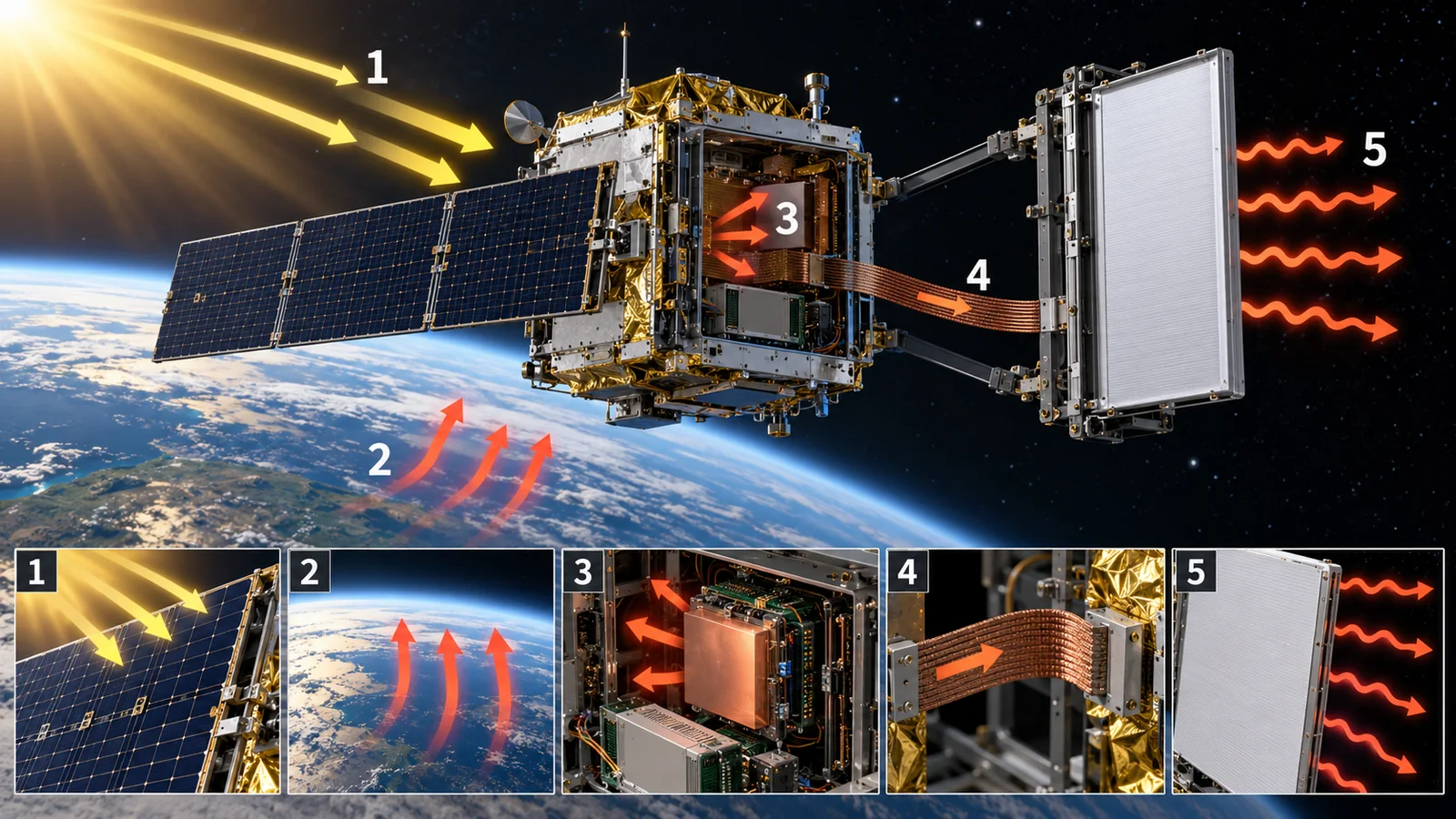
A spacecraft is not cooled by air as things are on the ground. How is its temperature set? The answer: it settles at the temperature where the heat coming in equals the heat going out. NASA's report writes the balance as an equation. What comes in is sunlight, sunlight reflected by the planet (albedo), the planet's infrared, and the equipment's own heat. What goes out is heat radiated to space. The difference is stored (heat capacity) Sourced[Ref. 1].
View original SVG, values and sources
Original SVG reference: Concept diagram (vector drawing). Heat flows into and out of a spacecraft. The equation and term names are from NASA's report [Ref. 1]; arrow widths do not show magnitude. Sunlight is about 1,361 W/m2 at Earth's distance (NASA's Earth fact sheet), and Earth's Bond albedo is 0.294 [Ref. 6].
Sunlight delivers about 1,361 W per square metre to a surface facing the Sun Sourced[Ref. 6]. The Earth reflects about 29 % of it (Bond albedo 0.294). Among all this, a material can set two numbers: how much sunlight a surface absorbs (solar absorptance α) and how much heat it throws away as infrared (emissivity ε).
Space's background is cold, but there is no air to carry heat. In vacuum, heat moves only by radiation and conduction, so equipment heat must be carried by conduction to a radiating surface and thrown away from there by radiation Sourced[Ref. 1]. On top of that, a spacecraft warms in sunlight and cools in shadow. Thermal control has three jobs: "cooling", "warming" and "damping the temperature swing".
3. Surface materials: solar absorptance α and emissivity ε
The exchange of heat with the outside world happens at the surface. NASA's report says that in thermal analysis the thermal spectrum is split into two bands: the solar band (shorter than 3 µm) and the infrared band (longer than 3 µm). How much sunlight a surface absorbs is α; how much heat it emits as infrared (and how much infrared from the Earth and the like it absorbs) is ε Sourced[Ref. 1].
What can combinations of α and ε do? NASA's report summarizes it this way. Matte black paint has a large α and a large ε: it absorbs sunlight and also sheds heat. Matte white paint has a small α and a large ε, so it reflects sunlight and sheds heat, which suits a radiator. Silver-coated FEP tape (a "second-surface" construction in which the silver behind the film reflects sunlight) also makes an excellent radiator surface.
It is a transparent film (FEP or similar) with silver deposited on its back, so that sunlight passes through the film and is reflected by the silver. Because the front is a transparent film, the film radiates the infrared and the silver reflects the sunlight: a division of labor that gives the radiator's ideal "small α, large ε". Where the analogy breaks down: the film degrades in space. If it cannot stay clear, α rises (next section).
Beginning of life (BOL) and end of life (EOL) are different numbers
The point a materials engineer most needs to watch is that a catalog α is a beginning-of-life value. NASA's report says coatings darken under atomic oxygen in low orbit and under ultraviolet light and cosmic rays at higher orbits, and α goes up. It adds that in thermal analysis the beginning-of-life (BOL) values serve the cold-side estimate and the end-of-life (EOL) values the hot-side estimate, and BOL values must not be used in an EOL calculation Sourced[Ref. 1].
For the white inorganic paint Z-93 (zinc oxide pigment in a potassium silicate binder), the following has been reported.
| Condition | Change in α | What the source says |
|---|---|---|
| Beginning-of-life value | α = 0.150, ε = 0.920 | A typical value obtained at a paint thickness of 0.15 mm or more. It stayed at 0.150 and 0.920 after a simultaneous low-orbit UV and atomic-oxygen test (7.2 × 10²⁰ atoms/cm2, 8,000 equivalent sun hours) |
| Ultraviolet alone | +0.010 (800 ESH), +0.028 (5,000 ESH) | No change in infrared emissivity |
| UV + electrons + protons (simulating 12 years at 1,375 km, 85 degrees inclination) | +0.022 (Z-93P) | +0.011 to 0.013 with UV only. No recovery in air |
| UV + electrons (Z-93) | +0.044 to 0.050 | Degradation is greatest at first and tends to plateau at about 2,000 ESH |
| AZ-93 (with MLP-300 primer) in orbit | No measurable change | 237 days on Mir and 3.956 years on MISSE on the ISS |
| Estimate from Lunar Orbiter V flight data | About +0.06 | With contamination uncertainty. A guide for a decade in the lunar environment |
All Sourced (Jaworske et al., NASA/TM—2008-215173 [Ref. 2]). The conditions, laboratories and material versions differ, so these are not to be ranked.
Another report (NASA tests of ISS thermal-control materials for contamination, ultraviolet light and atomic oxygen) says in its abstract that Z-93 darkened under vacuum ultraviolet light and was bleached by atomic oxygen but not back to its original brightness, and that samples contaminated by silicone (RTV) or Tefzel outgassing products darkened more Sourced[Ref. 3]. So outgassing comes back to thermal control as "contamination that raises α" (commentary).
On the ground we tend to judge paints and films by their as-shipped color and reflectance. In space the same paint's α rises by something like 0.05 (in the Z-93 examples) through ultraviolet light, particles, atomic oxygen and contamination. Given that those 0.05 cut a sunlit radiator's heat rejection by about 40 % (Chapter 4), a material is judged by its "post-degradation α". The darkening of polyimide on the outside of MLI under ultraviolet light (our explainer on polyimides for space) is the same story (commentary).
4. Radiators: throwing heat into space
A radiator is a surface for throwing heat into space by radiation. NASA's report describes it as a surface with high infrared emissivity and low solar absorptance ("radiator properties") Sourced[Ref. 1]. How much heat can a 1 m2 radiator reject? By the law of radiation (the Stefan-Boltzmann law), a surface emits ε × σ × T4 (σ is 5.670 × 10⁻⁸ W/m2K4, T the temperature in kelvin) Sourced[Ref. 7].
In shadow, assuming a 0 K background, the radiator can reject ε × σ × T4 = 0.92 × 5.670 × 10-8 × 2934 ≈ 385 W/m2. When sunlight falls head-on, the heat absorbed, α × 1,361 W/m2, is subtracted to give the net. With α = 0.15 (Z-93 at beginning of life) it is 385 − 204 ≈ 180 W/m2; with α = 0.20 (absorptance up by 0.05) it is 385 − 272 ≈ 112 W/m2. A 0.05 rise in absorptance cuts the net rejection by about 38 %. The area needed to reject 100 W is about 0.26 m2 in shade, about 0.55 m2 in sunlight with α = 0.15 and about 0.89 m2 in sunlight with α = 0.20 Our calculation.
Assumptions and limits: a radiator uniformly at 293 K, a 0 K background, an insulated back and no Earth albedo or infrared. In practice the most effective design move is to choose the radiator's orientation so that sunlight does not fall on it.
A radiator's performance is the product of the paint's α and ε (the material), the orientation (what it sees of the Sun and Earth) and the area. Trying to solve it by material alone means pushing α down further and further, yet α rises with time. NASA's report says that changing the spacecraft's orientation so that the radiator faces deep space is often combined with other methods Sourced[Ref. 1]. On a small satellite, where freedom in design is small, the choice of surface materials takes up most of the thermal design (commentary).
5. Multilayer insulation (MLI): a "blanket" that stops heat
Where heat should not flow in or out, multilayer insulation (MLI) is wrapped on. NASA's report describes an MLI blanket as made of inner layers of a thin low-infrared-emissivity material (usually 10 to 20 layers) and a durable outer layer. The many reflector layers limit the radiative transfer. The layers are embossed or alternated with thin netting to limit conduction between them. Perforations may be added so that trapped gas can vent. MLI protects the spacecraft from incoming solar and infrared flux and prevents unwanted heat loss to space Sourced[Ref. 1].
An example of the actual construction of an MLI blanket is in Chapter 6 of our explainer on polyimides for space. The MLI on LDEF had a 0.076 mm outer layer and fifteen layers of 0.0076 mm double-aluminized Kapton, separated by polyester net Sourced[Ref. 10].
MLI's effect is expressed as its effective emissivity ε* (the emissivity of the whole blanket regarded as a single surface). A NASA Goddard paper says that thermal analysis treats MLI as a radiative coupling of area times ε*, that ε* is derived from historical test data, and that it typically lies in the range 0.001 to 0.1 Sourced[Ref. 4]. Using this ε* for heat escaping from a 293 K surface to a 0 K background as ε* × σ × T4 (σT4 ≈ 418 W/m2) gives about 42 W/m2 at ε* = 0.1, about 4.2 W/m2 at 0.01 and about 0.42 W/m2 at 0.001. A bare dark surface (ε = 0.9, an illustrative assumption) is about 376 W/m2, so the reductions are about 1/9, 1/90 and 1/900 Our calculation.
Assumptions and limits: a simple model expressed by ε*, which leaves out the effects of seams, edges, attachments and penetrations.
NASA's report says MLI is delicate and its performance falls sharply when compressed (a thermal "short circuit"), smaller blankets lose efficiency because heat flow near the edges matters more, and the way it is attached creates a heat path. That is why MLI is unsuitable on the outside of a satellite that must fit tightly in a dispenser, such as a CubeSat Sourced[Ref. 1]. A JPL report says that the effective emissivity of MLI on propellant lines varies widely, mainly because of workmanship, and that this is the largest driver of line temperatures Sourced[Ref. 5].
Even if the MLI materials (aluminized films, netting) are standard products, the blanket's ε* shifts by orders of magnitude with seams, layer compression and attachment. If, as the JPL report says, workmanship is the main cause of the spread, improving the material alone will not stabilize ε*. From the materials side, MLI is a product of "the procedure that avoids contact between layers" rather than of "film performance", and the repeatability of that procedure, and ways to confirm it by inspection, are where the value lies (commentary). Also, the outer layer of the Hubble Space Telescope's MLI (aluminized Teflon FEP) became brittle in about 19 years Sourced[Ref. 11]. The life of the outer layer can be the life of the whole MLI.
6. The heat path: conduction and its "checkpoints"
Inside a satellite, though it is vacuum, heat moves mainly by conduction. NASA's report says that inside a sealed small satellite conductive heat transfer dominates, while the exchange with the outside is by radiation Sourced[Ref. 1]. Heat from electronic parts is carried through solids: board, bolts, chassis, radiating surface. Along this road are "checkpoints": the contact surfaces between parts.
NASA's report gives guideline thermal conductances of bolts of 0.21 to 3.51 W/K (stiff, small surfaces) and 0.105 to 1.054 W/K (large, thin surfaces), depending on screw size Sourced[Ref. 1]. For example, four 4-40 screws carrying 10 W produce a temperature drop of about 9.6 K across the bolted contacts alone for stiff surfaces and about 19 K for large thin surfaces; with 10-32 screws it is about 1.9 K and about 4.7 K Our calculation. Assumptions and limits: the table values are design guides and change with surfaces, torque and finish.
Even where a metal's thermal conductivity is high, the contact between a part and its chassis can limit the flow greatly. NASA's report lists, as ways to raise contact conductance, thermal interface materials (sheets, grease), conductive gaskets and thicker copper layers in the circuit board. It says thermal straps use not only copper and aluminum but also high-conductivity graphite (such as pyrolytic graphite sheet), and that in a comparison of straps of the same geometry made of aluminum, copper and graphite the graphite one had the higher thermal conductance Sourced[Ref. 1]. From the materials side, thermal management of a spacecraft is as much a job of "interface materials and fastening design" as of "high-conductivity materials" (commentary).
7. Moving and switching heat: heat pipes and heat switches
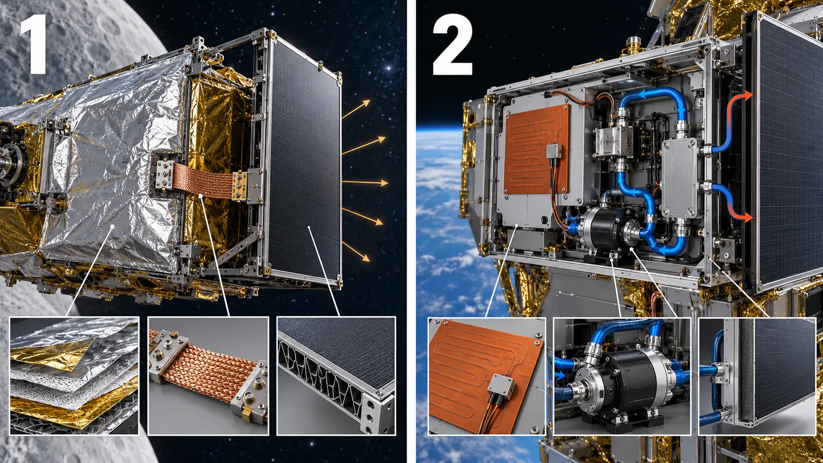
When heat must be carried far, or the path closed when it is cold, more tools come in. Here is NASA's report's thermal-control toolbox, arranged.
View original SVG, values and sources
Original SVG reference: Concept diagram (vector drawing). Passive (no power) and active (uses power) thermal-control technologies as NASA's report arranges them. The box at lower right gives the main point of the report's description.
How a heat pipe works
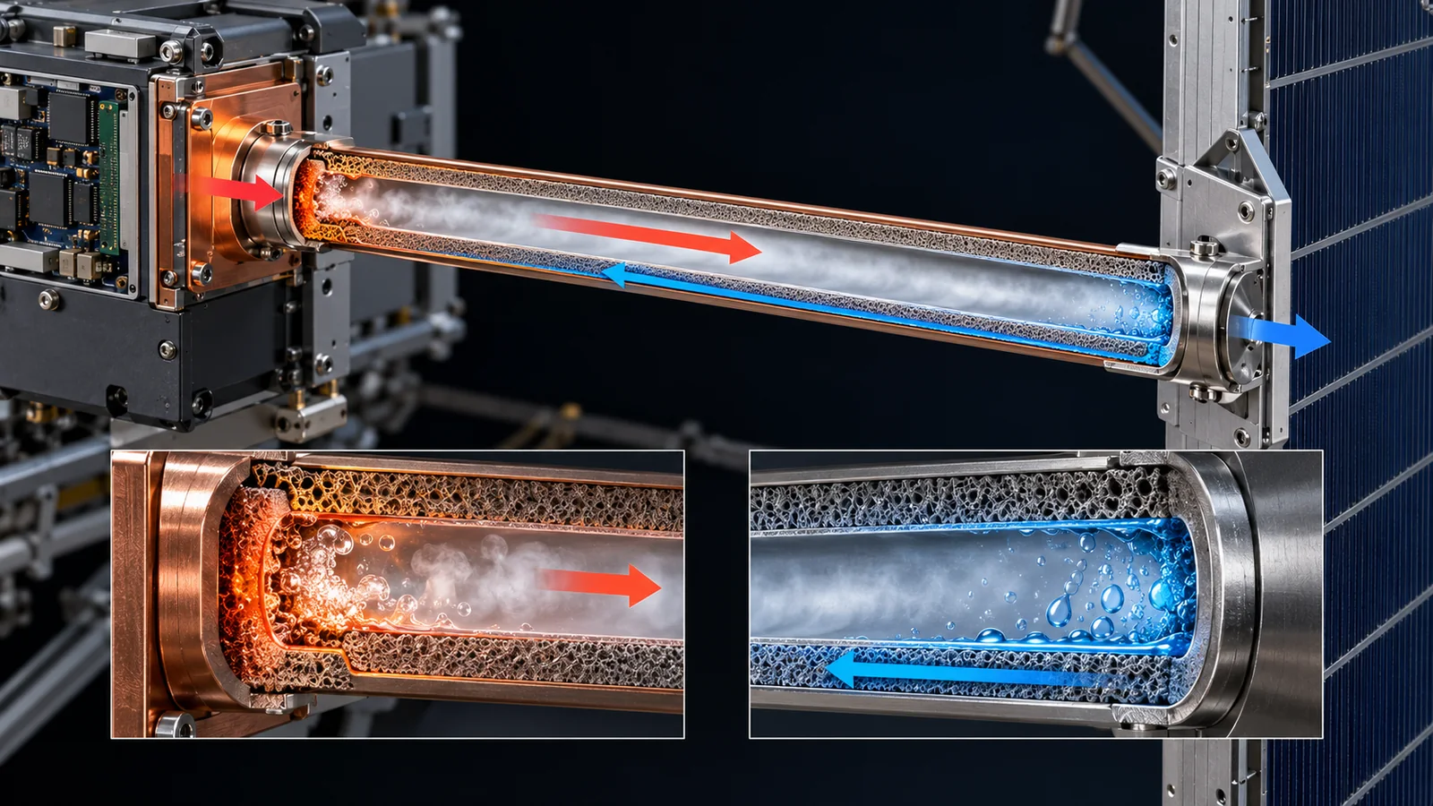
A heat pipe is a device that needs no power: a metal container holding a liquid and a porous wick (a capillary structure). At the end where heat is applied the liquid evaporates, the vapor moves to the cold end and condenses, and the liquid returns to the hot end by capillary action in the wick Sourced[Ref. 1].
View original SVG, values and sources
Original SVG reference: Concept diagram (vector drawing). How a heat pipe works (as described in NASA's report) and numbers for parts that switch heat. The numbers come from different sources and conditions and are not to be ranked.
NASA's report cites, as an example of a conventional constant-conductance heat pipe, BIRD, a 92 kg satellite launched in 2001, which used them to join satellite segments, and the flat-plate heat pipe on-orbit experiment (FOX), developed at JAXA, flown on SDS-4, a 50 kg spacecraft launched in 2012. A heat switch (a part that switches the heat path between strong and weak coupling) typically has a conduction ratio of 10:1, with a technology goal of 100:1 Sourced[Ref. 1]. On LDEF, an experiment with an ammonia variable-conductance heat pipe held within 0.3 °C of its set point for at least 45 days Sourced[Ref. 10].
8. Heat control that uses power: heaters and cooling
Heaters are used for parts, above all batteries, that must not get too cold in shadow. According to NASA's report, the most common heaters on small spacecraft are Kapton heaters: polyimide film with an etched metal-foil circuit that gives off heat when current flows. Many have a pressure-sensitive adhesive (PSA), and they are controlled by a thermostat or temperature sensor to warm parts with narrow temperature ranges such as batteries. Their TRL in low orbit is 7 to 9 Sourced[Ref. 1]. The NASA outgassing database also has a record for a Kapton product with the application "heater" (1974, record GSFC06212) [Ref. 13].
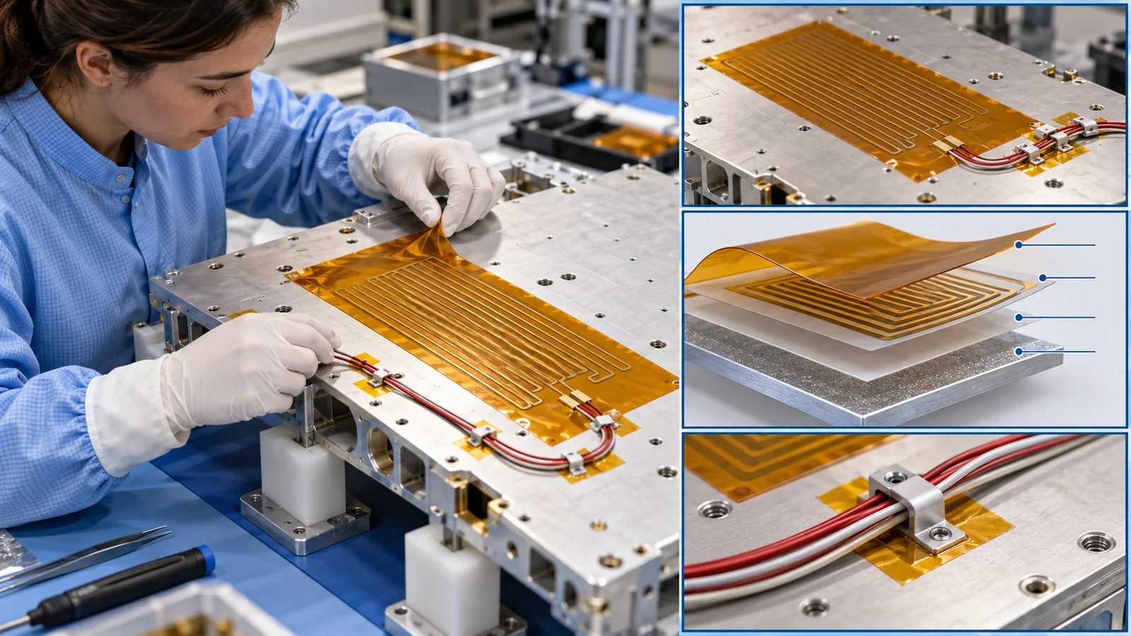
- Limits of heaters: among the products listed, the upper limit of PSA-bonded polyimide heaters is about 149 °C (a limit of the adhesive), the manufacturers' documents say (manufacturer's values). The 1U CubeSats Compass-1 and others used heaters for their batteries during eclipse Sourced[Ref. 1].
- Thermoelectric coolers (TEC): solid-state heat pumps that cool a spot with current. They have no moving parts and are quiet, but NASA's report says they are inefficient below 130 K, mechanically fragile and sensitive to thermal-expansion stress Sourced[Ref. 1]. Thermoelectric materials themselves are covered in our explainer on thermoelectric materials.
- Cryocoolers and fluid loops: used to cool infrared sensors and similar, but on small satellites power, mass and volume are tight constraints, and the report calls them still a new concept Sourced[Ref. 1].
9. Thermal control of small satellites: no room for MLI
Small satellites face particular difficulty in heat as well. NASA's report summarizes them: low thermal mass, so they react sharply to changing environments; limited external surface, so solar cells, radiating areas and windows compete for space; limited volume, so parts are thermally coupled easily; limited power; and electronics stacked closely, sometimes with no direct path to a radiator Sourced[Ref. 1].
As a real example, on Ten-Koh of the Kyushu Institute of Technology (altitude about 600 km) the CF/PEEK samples' temperature was about -40 to 20 °C each orbit, and sensors on nearby solar panels read an upper limit of 50 °C and a lower limit of -45 °C Sourced[Ref. 12]. On small satellites, NASA's report says, adhesive tapes such as silver FEP and standard surface finishes (anodizing, Alodine) have often been chosen instead of MLI. BioSentinel (6U, launched on Artemis I in 2022) used metallized tape and second-surface silvered FEP tape to control its external radiative properties and energy balance, and Picard (150 kg) used white paint on its Sun-facing side Sourced[Ref. 1].
The smaller a satellite, the smaller its heat capacity, the faster its temperatures swing, and the more its densely packed electronics trap heat. The difficulties listed in NASA's report are rather concentrated in small satellites. The thermal problem does not shrink when the satellite does.
10. Limits, and what could not be confirmed
- Thermal control of large satellites and probes: this article centers on NASA's report on small satellites and on materials reports. We do not cover primary sources on large radiators of geostationary satellites, loop heat pipes, heat shields of probes or fluid loops of crewed craft
- Numbers for infrared emissivity: the table behind Fig. 3 (Table 7-4 of NASA's report) lists only α (beginning of life), not ε. Apart from Z-93's ε (0.92) we do not cover it
- MLI effective emissivity: the range (0.001 to 0.1) is a statement in a NASA Goddard paper, and we could not confirm measured values of ε* for individual products
- End-of-life values: the α values in Fig. 3 are beginning-of-life typical values. End-of-life values differ by material, orbit and period, and we cover only the Z-93 example
- Calculations: the radiator, MLI and bolt calculations are illustrative values from simplified formulas, not predictions of any real vehicle's temperature
- The text of standards: we did not confirm the requirements in the text of ISO 15104 (paywalled) or of the ECSS standards
- ASTM: we did not open ASTM's site
11. How to read the yardsticks and standards
Thermal-control materials and design are evaluated by combining "numbers measured on the ground" with "analysis under space conditions". The yardsticks are: (1) the optical properties of surfaces (α, ε) and their degradation; (2) the effective emissivity of MLI; (3) the contact thermal resistance along heat paths; (4) temperatures in a thermal-vacuum environment (thermal-vacuum and thermal-balance tests); (5) whether the hardware survives thermal cycling; and (6) the validity of the heat-flow analysis model. They are values under test conditions and the assumptions of an analysis model, and they do not directly guarantee temperatures in orbit.
| What is evaluated | Typical test or method (name, source) | Standards and guidance (ECSS, ISO, NASA and others) | Cautions in reading |
|---|---|---|---|
| Thermal-control requirements in general | Design, analysis, manufacture, verification and operation (the set of requirements for a thermal-control subsystem) Sourced[Ref. 8] | ECSS-E-ST-31C "Thermal control" (15 November 2008) [Ref. 8] | Which requirements apply is set by contract. We did not check the text |
| Measuring α and ε | Methods for measuring solar absorptance by spectrometer and infrared emittance Sourced[Ref. 15] | ECSS-Q-ST-70-09C "Measurements of thermo-optical properties of thermal control materials" (2008) [Ref. 15] | It measures the value "at that moment". Measure again after irradiation to get the degraded value |
| Environmental testing (particles, UV, atomic oxygen, thermal cycling) | Ground simulated irradiation with optical measurements before and after Sourced[Ref. 2, 3] | ISO 15104:2025 "Space systems — Environmental testing for spacecraft thermal control materials" (ground tests for thermal-control materials; January 2025) [Ref. 19]. ECSS-Q-ST-70-06C "Particle and UV radiation testing for space materials" (2008) [Ref. 17] | Ground tests differ from the combined environment in orbit. We did not check the text of ISO 15104 |
| Thermal cycling (in vacuum) | A test that repeats temperature swings in vacuum to check the durability of bonds, coatings and metallized films Sourced[Ref. 14] | ECSS-Q-ST-70-04C "Thermal testing for the evaluation of space materials, processes, mechanical parts and assemblies" (2008) [Ref. 14] | We did not check the temperatures and cycle counts in the text |
| Durability of coatings | Sets out the kinds of test for the evaluation, qualification and acceptance of coatings | ECSS-Q-ST-70-17C "Durability testing of coatings" (1 February 2018) [Ref. 16] | Covers paints, metallic deposits and optical coatings. We did not check the text |
| Outgassing (contamination) | The NASA Goddard database; the test at 125 °C for 24 hours [Ref. 13] | ECSS-Q-ST-70-02C (RML < 1.0 %, CVCM < 0.10 %) [Ref. 18] | Released gas can settle on optical and radiating surfaces and change α (Chapter 3) |
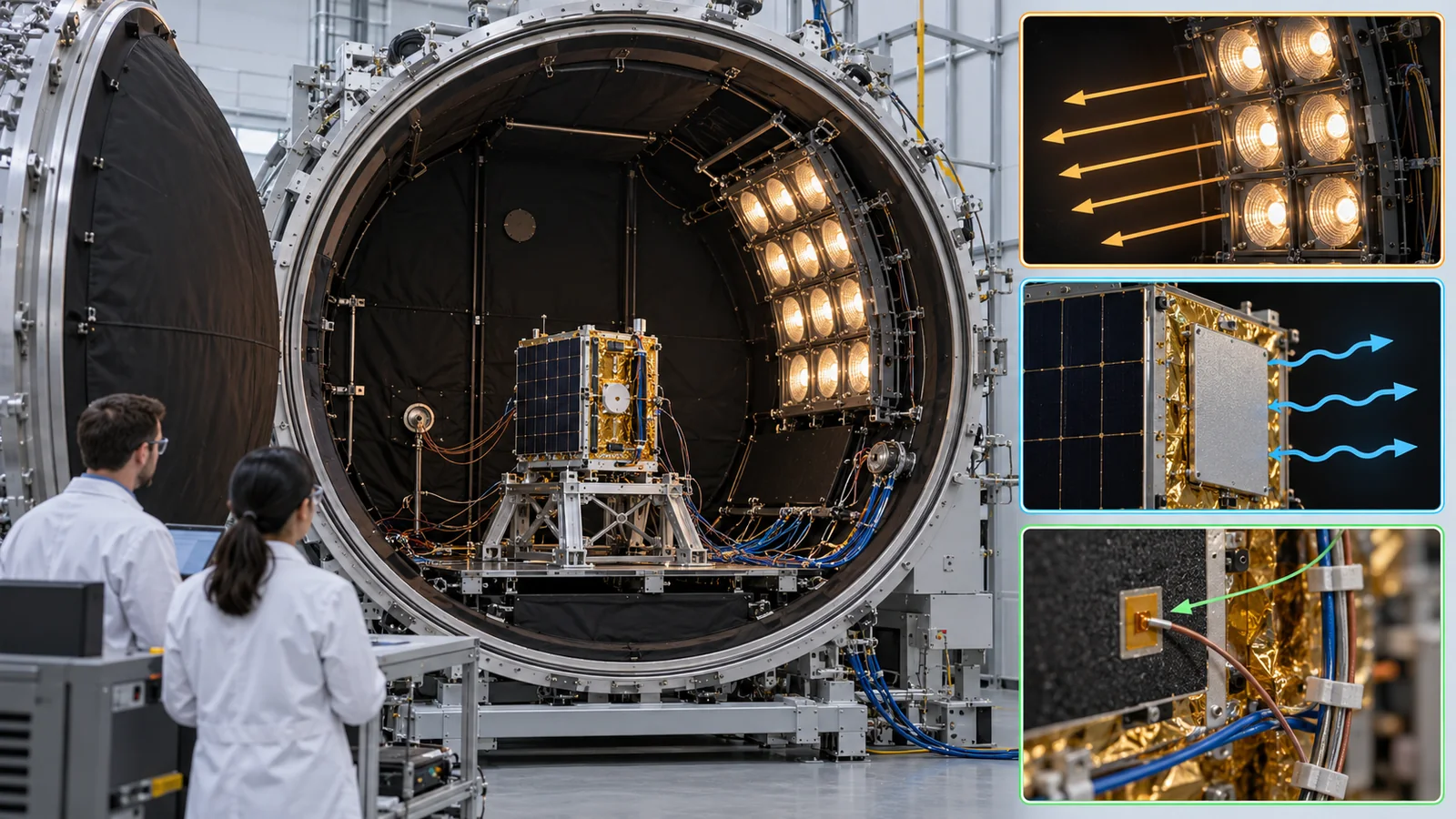
| Thermal-vacuum and thermal-balance tests | Tests that measure temperatures in a vacuum chamber under a Sun-like thermal environment (as in the concept figure) | ECSS-E-ST-10-03C Rev.1 "Testing" [Ref. 21]. GSFC-STD-7000 GEVS (Version B, 2021; not a NASA mandatory standard) [Ref. 20] | The test conditions are used to verify the analysis model. We did not check the text |
| Exchange of thermal-analysis data | A protocol for exchanging thermal-analysis models between software | ECSS-E-ST-31-04C "Exchange of thermal analysis data" (2018; requirements for the STEP-TAS protocol) [Ref. 9] | A standard for analysis software, not for materials |
The arrangement of this table is Our calculation (our own reordering). Standard numbers, titles and status were checked on the official pages of ECSS, ISO and NASA (checked 17 October 2026). ISO texts are paywalled, so we limited ourselves to titles and scope. We did not open ASTM's site.
Cautions in reading (for materials engineers)
- Beginning-of-life and end-of-life values are different: a catalog α is a beginning-of-life value. NASA's report says to use BOL for cold-side estimates and EOL for hot-side ones
- Ground tests and flight results are different things: ground irradiation tests of white paint and flight data from Mir and the ISS can disagree (the Z-93 examples)
- Check whether a standard is a recommendation or a requirement: ISO 15104 is a standard for test methods, and an ECSS standard becomes a requirement when a contract applies it
- Read the assumptions of the analysis model: a simplification such as effective emissivity ε* fails with seams, edges and workmanship (the JPL report)
12. Glossary
- Heat capacity
- The heat needed to raise the temperature by 1 K. The larger it is, the less the temperature moves.
- Albedo
- The fraction of sunlight a planet reflects. Earth's Bond albedo is 0.294.
- Solar absorptance (α)
- How much sunlight a surface absorbs (0 to 1).
- Emissivity (ε)
- How well a surface emits heat as infrared (0 to 1).
- Stefan-Boltzmann law
- A surface emits εσT4, with T the absolute temperature.
- Radiator
- A surface that throws heat to space by radiation. Small α and large ε.
- Second-surface mirror
- A transparent film with silver or similar on its back that reflects sunlight behind the film.
- OSR
- Optical Solar Reflector: a glass-based radiating-surface material with silver or similar that reflects sunlight.
- BOL / EOL
- Beginning / end of life. A surface's optical properties are degraded at EOL.
- ESH
- Equivalent sun hours: the amount of ultraviolet light expressed as hours in the Sun.
- MLI
- Multi-Layer Insulation: an insulating blanket of stacked thin reflective layers.
- Effective emissivity (ε*)
- The emissivity of a whole MLI blanket regarded as one surface. Reported in the range 0.001 to 0.1.
- Thermal strap
- A flexible heat bridge of copper, aluminum or graphite.
- Thermal interface material (TIM)
- A sheet or grease placed between parts to improve heat flow.
- Contact thermal conductance
- How well heat passes through a contact surface (W/K).
- Heat pipe
- A power-free device that carries heat by evaporating and condensing a liquid.
- Wick
- The porous structure in a heat pipe that returns the liquid by capillary action.
- VCHP
- Variable-conductance heat pipe: its conductance changes automatically.
- Heat switch
- A part that switches the heat path between strong and weak coupling.
- PCM (phase-change material)
- A material that levels temperature swings using the heat of melting and freezing.
- TEC
- Thermoelectric cooler: a solid-state heat pump that cools a spot with current.
- Thermal-vacuum test
- A test that exposes hardware to a space-like temperature environment inside a vacuum chamber.
- ECSS
- European Cooperation for Space Standardization. Europe's cooperative body for space standards.
13. References
- NASA (Small Spacecraft Systems Virtual Institute) "State-of-the-Art of Small Spacecraft Technology", Chapter 7 Thermal Control (2026 edition; checked 17 October 2026) — nasa.gov/smallsat-institute/sst-soa/thermal-control/
- Jaworske D. A., Kline S. E. (NASA Glenn) "Review of End-of-Life Thermal Control Coating Performance", NASA/TM—2008-215173 (April 2008) — ntrs.nasa.gov/citations/20080018585
- Visentine J., Finckenor M., Zwiener J., Munafo P. "Effects of Contamination, UV Radiation, and Atomic Oxygen on ISS Thermal Control Materials" (2001; abstract only) — ntrs.nasa.gov/citations/20010084631
- Peabody H. L., Evans C. (NASA Goddard) "Alternate Approach to Multi-Layer Insulation Modeling to Reduce Node Count", ICES-2023-77 (July 2023) — ntrs.nasa.gov/citations/20230005990
- Miller J. R. et al. (JPL) "MLI Blanket Effective Emittance Variance and Its Effect on Spacecraft Propellant Line Thermal Control" (abstract only) — ntrs.nasa.gov/citations/20190025589
- NASA NSSDC "Earth Fact Sheet" (solar irradiance 1361.0 W/m2, Bond albedo 0.294, GM; checked 17 October 2026) — nssdc.gsfc.nasa.gov/planetary/factsheet/earthfact.html
- NIST "Stefan-Boltzmann constant" (5.670 374 419... x 10^-8 W/m2K4) — physics.nist.gov/cgi-bin/cuu/Value?sigma
- ECSS ECSS-E-ST-31C "Thermal control" (15 November 2008) — ecss.nl/standard/ecss-e-st-31c-thermal-control/
- ECSS ECSS-E-ST-31-04C "Exchange of thermal analysis data" (1 February 2018) — ecss.nl/standard/ecss-e-st-31-04c-exchange-of-thermal-analysis-data-1-february-2018/
- Smith C. A., Hasegawa M. M., Jones C. A. (McDonnell Douglas Aerospace) "Space Station WP-2 application of LDEF MLI results", LDEF Materials Results for Spacecraft Applications (NASA Marshall, conference paper, December 1993) — ntrs.nasa.gov/citations/19940026511
- de Groh K. K. et al. "Analyses of Hubble Space Telescope Aluminized-Teflon Multilayer Insulation Blankets Retrieved After 19 Years of Space Exposure" (2015) — ntrs.nasa.gov/citations/20150002706
- Abdullah F., Okuyama K., Fajardo I., Urakami N. (Kyushu Institute of Technology) "In Situ Measurement of Carbon Fibre/Polyether Ether Ketone Thermal Expansion in Low Earth Orbit", Aerospace 7(4), 35 (2020), DOI 10.3390/aerospace7040035 — doi.org/10.3390/aerospace7040035
- NASA Goddard Outgassing Database (searchable test results; checked 17 October 2026) — outgassing.nasa.gov/
- ECSS ECSS-Q-ST-70-04C "Thermal testing for the evaluation of space materials, processes, mechanical parts and assemblies" (15 November 2008) — ecss.nl/standard/ecss-q-st-70-04c-thermal-testing-for-the-evaluation-of-space-materials-processes-mechanical-parts-and-assemblies/
- ECSS ECSS-Q-ST-70-09C "Measurements of thermo-optical properties of thermal control materials" (31 July 2008) — ecss.nl/standard/ecss-q-st-70-09c-measurements-of-thermo-optical-properties-of-thermal-control-materials/
- ECSS ECSS-Q-ST-70-17C "Durability testing of coatings" (1 February 2018) — ecss.nl/standard/ecss-q-st-70-17c-durability-testing-of-coatings/
- ECSS ECSS-Q-ST-70-06C "Particle and UV radiation testing for space materials" (31 July 2008) — ecss.nl/standard/ecss-q-st-70-06c-particle-and-uv-radiation-testing-for-space-materials/
- ECSS ECSS-Q-ST-70-02C "Thermal vacuum outgassing test for the screening of space materials" (15 November 2008; checked on the ECSS page and PDF) — ecss.nl/standard/ecss-q-st-70-02c-thermal-vacuum-outgassing-test-for-the-screening-of-space-materials/
- ISO ISO 15104:2025 "Space systems — Environmental testing for spacecraft thermal control materials" (edition 1, January 2025; checked on the ISO page) — iso.org/standard/84447.html
- NASA Goddard GSFC-STD-7000 "General Environmental Verification Standard (GEVS) for GSFC Flight Programs and Projects" (Version B, 28 April 2021; checked on the NASA Standards page) — standards.nasa.gov/standard/GSFC/GSFC-STD-7000
- ECSS ECSS-E-ST-10-03C Rev.1 "Testing" (31 May 2022) — ecss.nl/standard/ecss-e-st-10-03c-rev-1-testing-31-may-2022/
14. Claim-to-source audit
| Claim in the text | Basis | Class |
|---|---|---|
| The heat-balance equation and its terms, that only radiation and conduction operate in vacuum, the splitting of wavelength bands (3 µm), the properties of black and white paints and silver FEP tape, the treatment of BOL and EOL, the construction of MLI (10 to 20 layers, netting, perforations) and the effects of compression, edges and attachment, that CubeSats have little room for MLI, thermal straps and graphite, the bolted-joint conductances of Table 7-6, interface materials, how heat pipes work, BIRD and SDS-4 (FOX), the heat-switch ratio of 10:1 and goal of 100:1, the variable-conductance example, Kapton heaters, TECs, cryocoolers, fluid loops, the thermal difficulties of small satellites, the BioSentinel and Picard examples, and the α values of Table 7-4 | NASA's report, Chapter 7 Reference 1 https://www.nasa.gov/smallsat-institute/sst-soa/thermal-control/ | Sourced |
| Z-93's α of 0.150 and ε of 0.920, the changes in α from ultraviolet light, electrons, protons and atomic oxygen (+0.010, +0.028, +0.022, +0.044 to 0.050), AZ-93 in orbit, and the Lunar Orbiter V estimate (about +0.06) | Jaworske and Kline (NASA/TM—2008-215173) Reference 2 https://ntrs.nasa.gov/citations/20080018585 | Sourced |
| That Z-93 darkens under ultraviolet light and is bleached by atomic oxygen but does not fully recover, and that outgassing contamination darkens it more | Visentine et al. (abstract only) Reference 3 https://ntrs.nasa.gov/citations/20010084631 | Sourced |
| The typical range of MLI e* (0.001 to 0.1) and that thermal analysis treats it as a coupling of area times e* | Peabody and Evans (ICES-2023-77) Reference 4 https://ntrs.nasa.gov/citations/20230005990 | Sourced |
| That the effective emissivity of MLI varies with workmanship and is the main driver of line temperatures | Miller et al. (JPL; abstract only) Reference 5 https://ntrs.nasa.gov/citations/20190025589 | Sourced |
| Solar irradiance of 1361.0 W/m2 and Earth's Bond albedo of 0.294. The Stefan-Boltzmann constant of 5.670 × 10⁻⁸ W/m2K4 | NASA NSSDC Earth fact sheet, NIST Reference 6 https://nssdc.gsfc.nasa.gov/planetary/factsheet/earthfact.html Reference 7 https://physics.nist.gov/cgi-bin/cuu/Value?sigma | Sourced |
| The LDEF MLI construction (0.076 mm outer layer, fifteen layers of 0.0076 mm double-aluminized Kapton, netting) and that a variable-conductance heat pipe held within 0.3 °C of its set point for 45 days or more. That the outer layer of Hubble's MLI became brittle | Smith et al. (LDEF conference proceedings), de Groh et al. (2015) Reference 10 https://ntrs.nasa.gov/citations/19940026511 Reference 11 https://ntrs.nasa.gov/citations/20150002706 | Sourced |
| The Ten-Koh sample temperature (-40 to 20 °C) and solar-panel sensors (-45 to 50 °C). The record for a Kapton product with the application "heater" (GSFC06212) | Abdullah et al., NASA Goddard Outgassing Database Reference 12 https://doi.org/10.3390/aerospace7040035 Reference 13 https://outgassing.nasa.gov/ | Sourced |
| The titles, scope and status of ISO 15104:2025, GEVS (Version B), ECSS-E-ST-31C, 31-04C, 10-03C and ECSS-Q-ST-70-02C, 04C, 06C, 09C and 17C | ISO, NASA and ECSS official pages Reference 19 https://www.iso.org/standard/84447.html Reference 20 https://standards.nasa.gov/standard/GSFC/GSFC-STD-7000 Reference 8 https://ecss.nl/standard/ecss-e-st-31c-thermal-control/ Reference 9 https://ecss.nl/standard/ecss-e-st-31-04c-exchange-of-thermal-analysis-data-1-february-2018/ Reference 21 https://ecss.nl/standard/ecss-e-st-10-03c-rev-1-testing-31-may-2022/ Reference 18 https://ecss.nl/standard/ecss-q-st-70-02c-thermal-vacuum-outgassing-test-for-the-screening-of-space-materials/ Reference 14 https://ecss.nl/standard/ecss-q-st-70-04c-thermal-testing-for-the-evaluation-of-space-materials-processes-mechanical-parts-and-assemblies/ Reference 17 https://ecss.nl/standard/ecss-q-st-70-06c-particle-and-uv-radiation-testing-for-space-materials/ Reference 15 https://ecss.nl/standard/ecss-q-st-70-09c-measurements-of-thermo-optical-properties-of-thermal-control-materials/ Reference 16 https://ecss.nl/standard/ecss-q-st-70-17c-durability-testing-of-coatings/ | Sourced |
| The heat rejection in Fig. 4 (385, 180, 112 W/m2), the areas needed (0.26, 0.55, 0.89 m2), the fall in net rejection (about 38 %), the heat flows in Fig. 5 (42, 4.2, 0.42, 376 W/m2) and ratios (about 1/9, 1/90, 1/900), and the temperature drops in Fig. 6 (9.6, 19, 6.0, 14, 1.9, 4.7 K) | Our calculation (assumptions in the text). Not values of a real vehicle | Our calculation |
| Readings such as "use thermal-control materials at end-of-life numbers", "a radiator is material times orientation times area", "MLI performance moves with workmanship more than material", "heat is decided by contact too" and "outgassing comes back to thermal control as raised α" | This article's organization and commentary based on published content. Not views stated by any of the organizations | Commentary |
| Thermal control of large satellites and probes, infrared-emissivity numbers (other than Z-93), e* of individual MLI blankets, end-of-life values of each material, and the text of ISO 15104 and the ECSS standards | Not confirmed within the range of primary sources this article could reach, so not stated | Commentary |
| That, of Figs. 1 to 9, Figs. 1 and 9 (AI image frames) are illustrative concept images, and that the other figures are drawings for explanation, not observations of real data | A note by this article | Commentary |
Last updated: 17 October 2026 / Sources are limited to primary materials (NASA's report on small-spacecraft technology, NASA technical reports, NASA NSSDC, NIST, the official pages of ECSS, ISO and NASA, and peer-reviewed papers). The heat rejection, heat flows and temperature drops are illustrative calculations made for this article and do not predict the temperature of a real spacecraft. The α of paints and films is a typical beginning-of-life value and changes by end of life. We could not confirm the thermal control of large satellites, infrared-emissivity numbers, the effective emissivity of individual MLI blankets, or the requirements in the standards' texts, so we do not state them.