TECHNOLOGY EXPLAINER
The Space Environment and Its Effects on Materials
— the "five enemies", by low Earth orbit, geostationary orbit and the lunar surface
A material that lasts for years on the ground can crack, cloud or erode away in a short time in space, because space lies in wait with five enemies: vacuum, radiation, temperature swings, atomic oxygen with ultraviolet light, and microgravity with debris. This article sorts the five enemies by place: low Earth orbit, geostationary orbit and the lunar surface. Every number carries its orbit, shielding and period, and we show how far ground tests can reproduce space.
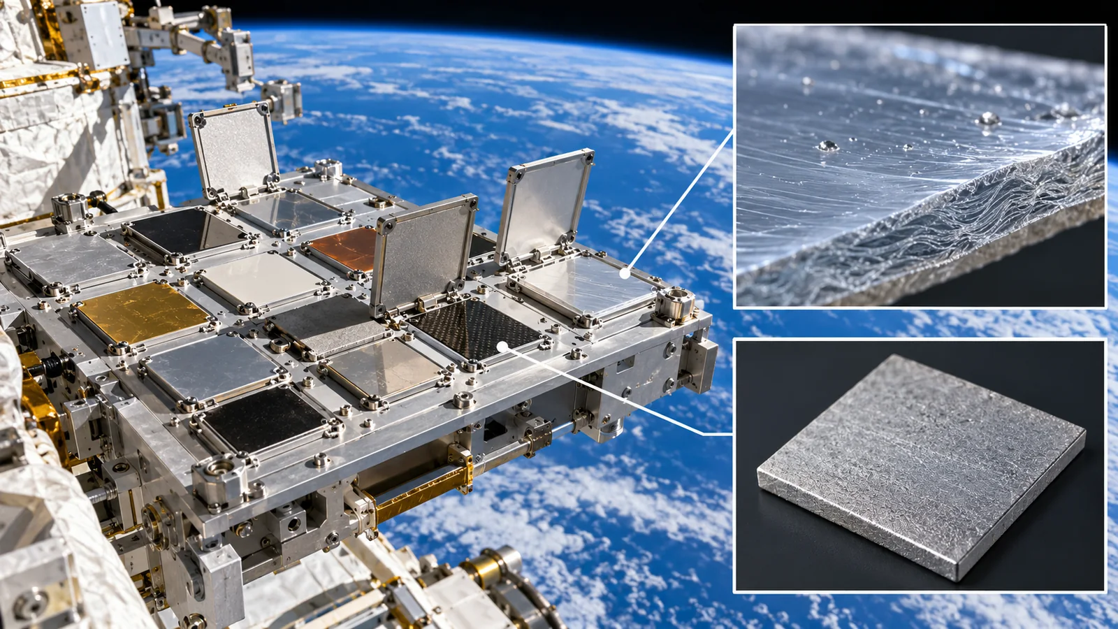
- The short version / what to know first / where this sits in the series
- Different environments in different places: three places, five enemies
- Enemy 1, vacuum: heat cannot escape easily and materials give off gas
- Enemy 2, radiation: belts, dose and shielding
- Enemy 3, temperature swings: 16 cycles a day, and the lunar day and night
- Enemy 4, atomic oxygen and ultraviolet light: surfaces erode and discolor
- Enemy 5, microgravity and debris: free fall and high-speed impacts
- The enemies combine: real examples
- How far ground tests reproduce space
- How to read the yardsticks and standards / limits / glossary / references / claim-to-source audit
Sourced = stated in a public document (source linked)
Our calculation = a value we derived from stated assumptions
Not yet confirmed = plans or items still being drafted
Our reading for materials is marked Commentary. Inference is shown in bold. Every analogy comes with its limits.
Space-environment numbers change a great deal with orbit, altitude, period and shielding. We state conditions beside each number and avoid blanket phrases such as "space is X degrees". Calculations are illustrative values we computed, not values for real vehicles. Radiation doses can differ by orders of magnitude between sources; when they do, we treat them as orders of magnitude and say so. Because this field changes fast, standards and documents carry a checked date (17 October 2026).
1. The short version / what to know first / where this sits in the series
- The "five enemies" differ in strength from place to place. Atomic oxygen and temperature cycling stand out in low Earth orbit, radiation in geostationary orbit, and the day-night temperature swing and dust on the Moon (our grouping).
- In numbers: the vacuum outside the ISS is 10⁻⁶ to 10⁻⁹ torr, and a low-orbit surface swings about 16 times a day, with a rule of thumb of −120 to +120 °C [Ref. 1]Sourced. About four years of atomic oxygen erodes polyimide (Kapton H) by roughly 0.25 mm [Ref. 2]Our calculation.
- Ground tests cannot reproduce all of space. Vacuum reproduces well, while atomic-oxygen facilities and debris impact speeds still differ from orbit [Ref. 1]Sourced.
No prior knowledge is needed. The idea of an orbit ("falling while moving sideways") and the altitudes and periods of low Earth orbit, geostationary orbit and the Moon are explained in the entry article, the introduction to the space industry. Necessary points are repeated briefly here so that this article stands alone. Equations are kept to a minimum; each is explained in words and checked with numbers.
Read this article after the entry article, the introduction to the space industry. The "five enemies" are the common vocabulary of the whole series. Next comes the article on how to read evaluations of space materials (how these environments are tested and which standards confirm the results). Heat rejection is covered in the articles on spacecraft thermal control and on thermal-control materials, electronics in the one on radiation and electronic parts, and debris in the one on on-orbit servicing and space debris.
2. Different environments in different places: three places, five enemies
Asked "how hot is space?" or "how much radiation is there in space?", we have no single answer. In low Earth orbit where the ISS flies, in the geostationary orbit of communications satellites, and on the Moon, the same enemy has completely different strength. The matrix gathers how the five enemies appear in three places. Numbers and conditions are checked with sources in sections 3 to 7.
Temperature is not "the temperature of space" but the temperature of an object. With no air to carry heat, a sunlit object grows hot and a shaded one cools (section 3). The lunar surface has a gravity of about 0.165 of Earth's (1.62 m/s²): it is a place with ordinary gravity, not microgravity [Ref. 6]Sourced. Microgravity is not the absence of gravity but the state of free fall (see the entry article).
3. Enemy 1, vacuum: heat cannot escape easily and materials give off gas
A thermos keeps its contents warm for hours because the space between its double walls is evacuated, cutting off heat carried by air (convection and conduction) (our commentary). Space is this "vacuum" spread all around. The heat that equipment itself produces also escapes with difficulty in vacuum.
(1) How good a vacuum
NASA's guide gives the hard vacuum outside the ISS as 10⁻⁶ to 10⁻⁹ torr [Ref. 1]Sourced. The torr is a unit of pressure; one atmosphere is 760 torr. Converted, 10⁻⁶ to 10⁻⁹ torr is about 1.3×10⁻⁴ to 1.3×10⁻⁷ Pa, roughly a billionth to a trillionth of atmospheric pressure Our calculation. The night-time surface pressure on the Moon is about 3×10⁻¹⁵ bar (2×10⁻¹² torr) in NASA's data [Ref. 6]Sourced. We could not confirm a pressure value for geostationary orbit.
(2) Effect 1: heat leaves only by radiation
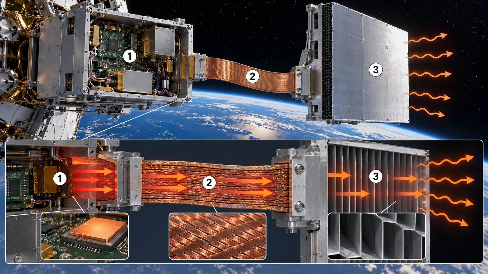
On the ground, a hot object loses heat by three routes: conduction (passing through contact), convection (carried by moving air) and radiation (leaving as infrared). With no air in vacuum, there is no convection. Radiation is the only way out for heat (upper part of Fig. 3).
What, then, fixes the temperature of a plate left in the sun? The heat coming in is the share of sunlight the plate absorbs (absorptance α). The heat going out is what the plate radiates as infrared (emissivity ε). The temperature settles where the two balance, which gives T = (α·S / (ε·σ))1/4. S is the solar irradiance (1361 W/m² in NASA's Moon data and in ECSS [Ref. 6, 3]) and σ is the Stefan-Boltzmann constant (5.670×10⁻⁸ W/m²K⁴ [Ref. 16]).
Check it with numbers. A plate with α/ε of 0.25 reaches about 5 °C, 0.5 about 58 °C, 1.0 about 120 °C, and 1.5 about 162 °C Our calculation. In the same sunshine, the surface material's properties (α and ε) shift the temperature by more than 100 °C. The 120 °C at α/ε of 1.0 is nearly the same as the rule-of-thumb +120 °C for low-orbit surfaces in section 5.
View original SVG, values and sources
Original SVG reference: Drawing with our calculation (vector drawing). In vacuum, heat leaves only by radiation. The upper part contrasts the ways heat can leave on the ground and in vacuum (concept). The lower part shows the equilibrium temperature of a plate facing the Sun squarely (our calculation): T = (α·S/(ε·σ))^(1/4), S = 1361 W/m², σ = 5.670×10⁻⁸. The back is insulated and Earth's heat is ignored, so this is idealized and not the temperature of any real vehicle.
To make α/ε small so that a sunlit surface does not get too hot. White paint absorbs little sunlight (small α) and radiates infrared well (large ε). Gold or silver insulation is a trick to keep heat from leaking inside. The article on thermal-control materials and radiative cooling covers this. Limits of the analogy: a real vehicle also feels its own internal heat, heat arriving from the Earth (ECSS gives Earth's infrared as 230 W/m² on average, 150 to 350 W/m² for an orbiting vehicle [Ref. 3]) and the other parts of the vehicle.
(3) Effect 2: materials give off gas (outgassing)
In vacuum, volatile components inside a material escape. This is outgassing. NASA's guide notes that the released molecules deposit on line-of-sight surfaces, especially cold ones, and can affect optical surfaces and spacecraft performance [Ref. 1]Sourced. The ECSS environment standard lists what comes off: water, solvents, additives, uncured monomer, lubricants and contamination from ground processing and handling [Ref. 3]Sourced.
One countermeasure is a bake-out: heating in vacuum beforehand to drive off volatiles. NASA's guide says a material known to outgas should be vacuum-baked for at least 24 hours at a temperature above that expected in orbit (100 °C if that is unknown) [Ref. 1]Sourced. For the ISS, limits on external contamination are set in a document (NASA SSP 30426) and the list of materials used is reviewed in advance [Ref. 1]Sourced.
Solvents and unreacted components left in adhesives, rubbers, paints and resins, never noticed on the ground, can deposit on nearby cold lenses or sensors in vacuum and degrade performance. In space, the selection criterion is not only a material's performance but what comes off it and how much (our commentary). Bake-out conditions and outgassing tests are covered in the next article on reading evaluations.
4. Enemy 2, radiation: belts, dose and shielding
Space radiation is not only light-like rays (such as X-rays) but fast particles (electrons and protons). Fast particles break bonds in materials and create charge inside electronic parts. NASA's guide lists three natural sources of charged-particle radiation: galactic cosmic rays (high-energy particles from far away), solar proton events (particles that surge after solar explosions) and the trapped radiation belts [Ref. 1]Sourced.
(1) The radiation belts and where the orbits sit
Earth's magnetic field captures charged particles and holds them in belts: the radiation (Van Allen) belts. The ECSS environment standard says the belts extend from 100 to 65,000 km in altitude, with electrons up to a few MeV and protons up to several hundred MeV [Ref. 3]Sourced. The South Atlantic Anomaly is where the inner edge of the belts dips to low altitude [Ref. 3]Sourced. The ISS receives most of its particle dose crossing this region (mostly electrons; the proton dose is also significant for some materials and parts) [Ref. 1]Sourced.
(2) How large is the dose
The amount of radiation a material or part receives is the absorbed dose, in Gy (gray) or rad. 1 Gy = 100 rad, and 1 Gy is 1 J of energy absorbed per kilogram of material. For electronic parts, dose is usually the amount absorbed by silicon, written rad(Si) or Gy(Si). Even in the same orbit, dose varies greatly with the thickness of metal around the part (shielding).
A NASA technical report (NASA/TM-20220011775) estimates dose for one-year design reference missions, assuming 5 mm of aluminum shielding and using SHIELDOSE-2 in SPENVIS (a European space-environment computation system) [Ref. 4]. Its annual total absorbed doses are 136 rad for low-inclination LEO (avoiding the SAA), 333 rad for polar LEO, 430 rad for an ISS-like orbit (500 km, 51° inclination), 2,150 rad for a lunar cruise and 5,930 rad for geostationary orbit Sourced.
And on the lunar surface? The dosimeter (Lunar Lander Neutrons and Dosimetry, LND) of China's Chang'E-4 lander made the first direct measurements of radiation on the Moon after landing on 3 January 2019 in the von Kármán crater on the far side. The average absorbed dose rate in silicon was 13.2 ± 1 µGy/hour, with average shielding around the instrument of about 3.5 mm aluminum equivalent [Ref. 8]Sourced. No solar particle event was observed in that period, and solar activity was approaching its minimum. The paper states that such events can raise the dose by orders of magnitude behind thin shielding [Ref. 8].
13.2 µGy/hour is about 0.32 mGy a day, or about 0.12 Gy (about 12 rad) a year Our calculation. This simply extends the observation period's average to a year and excludes solar particle events. Because shielding and method differ from the table above (5 mm aluminum, calculated), we do not compare them as larger or smaller.
(3) Shielding does not simply reduce dose in proportion to thickness
The NASA report states that with 2 mm of aluminum the electron contribution becomes negligible, at 5 mm the proton shielding effectiveness bottoms out, and beyond 5 mm even 20 mm of aluminum reduces the dose by only about another factor of two [Ref. 4]Sourced. As particles pass through metal, the spectrum shifts toward higher energies (beam hardening), because particles easily stopped by thin shielding are removed first. That is why shielding is designed by layering several materials.
(4) Effects on materials and parts
In polymers, particle radiation either links molecular chains (cross-linking) or cuts them (chain scission), leaving the material hard and brittle [Ref. 1]Sourced. NASA's guide says that for most ISS materials the effects of atomic oxygen and UV can overshadow those of particle radiation [Ref. 1]. The greater effect is on avionics: single-event upsets (one particle flips a bit), bit errors and latch-up (overcurrent that stops operation) [Ref. 1]Sourced. Mitigations are choosing radiation-hard parts, shielding, error-correcting circuits and triple redundancy (majority vote) [Ref. 1].
NASA's guide says that for testing a thermal-control coating 3 to 5 mil thick (about 76 to 127 µm), electrons and protons of 40 to 700 keV have the most effect on optical properties and coating chemistry; higher-energy particles pass through the coating and affect the substrate [Ref. 1]Sourced. So for thin films, what matters is not only "dose" but which particles of what energy stop at what depth (the relation between dose and depth). For testing upsets in electronics, by contrast, higher energies of 1 to 70 MeV are used [Ref. 1].
Advice on radiation protection for people's health and safety is outside this article. The doses shown help to understand the environment of materials and parts.
5. Enemy 3, temperature swings: 16 cycles a day, and the lunar day and night
The temperature problem is not only "how hot at the maximum". How many times it swings back and forth decides how a material tires.
(1) Low Earth orbit: about 16 times a day
The ISS circles the Earth in about 92 minutes and moves between sunlight and shadow about 16 times a day [Ref. 1]Sourced. NASA's guide gives −120 °C to +120 °C as a rule of thumb for this swing, though a surface with high solar absorptance and low infrared emissivity swings further. The actual temperature depends on the surface properties, its view of the Sun, the Earth and other parts of the vehicle, the time in sunlight and shadow, and thermal mass and equipment heat [Ref. 1]Sourced.
Sixteen cycles a day is about 5,840 a year; over an assumed 15 years it would be about 88,000 Our calculation (15 years is a period we assume as an example). What matters here is a mismatch in the coefficient of thermal expansion (CTE). If a coating and its substrate expand differently, only one of them stretches and shrinks more at every swing, causing cracks, peeling, spalling and pinholes. Once there is a hole, atomic oxygen attacks the material beneath [Ref. 1]Sourced. NASA's guide shows a case in MISSE-4 (a materials exposure experiment outside the ISS) in which thermal cycling and atomic-oxygen erosion together destroyed two thin-film coatings [Ref. 1].
(2) Geostationary orbit: mostly sunlit, with two "shadow seasons" a year
In geostationary orbit a satellite is usually in sunlight almost all the time. NOAA explains that the GOES weather satellites pass through two periods a year in Earth's shadow, during which they run on batteries up to 72 minutes each day; the shadow periods run roughly from late February to mid-April and from late August to mid-October [Ref. 5]Sourced. Each season lasts about 45 to 49 days, so there are about 90 days a year with one shadow a day Our calculation (a rough estimate from NOAA's dates).
(3) The lunar surface: day and night of about two weeks each
A lunar day (from one noon to the next) is about 29.53 days [Ref. 6]Sourced. In NASA's Moon data the equatorial surface temperature swings widely, from 95 K to 390 K (about −178 °C to +117 °C) [Ref. 6]Sourced. In permanently shadowed craters at the poles, the Diviner instrument (a thermal mapper) on NASA's Lunar Reconnaissance Orbiter recorded places on crater floors as cold as −248 °C [Ref. 7]Sourced. The cycles are few, about 12 a year (365.25 days ÷ 29.53 days) Our calculation.
Low Earth orbit has both a wide range and about 500 times as many cycles as the lunar surface (5,840 ÷ 12) Our calculation. What counts is not a single material's heat resistance but the difference in thermal expansion between bonded materials. Thin coatings, adhesive layers, composite interlayers and solder joints, the boundaries of dissimilar materials, are where fatigue breaks things (our commentary). The lunar surface has few cycles but a wide day-night range (about 300 K) and a two-week night to bridge (keep heat or shed it).
6. Enemy 4, atomic oxygen and ultraviolet light: surfaces erode and discolor
For materials in low Earth orbit, the toughest enemy is atomic oxygen (AO). NASA's guide calls AO the most significant cause of material degradation at ISS altitude [Ref. 1]Sourced.
(1) What atomic oxygen is
The oxygen in ground-level air is a molecule of two joined atoms (O₂). High up, short-wavelength ultraviolet light from the Sun splits O₂ into single oxygen atoms: atomic oxygen. In low Earth orbit, below about 1,000 km, it is the most abundant species. At 400 km an atom travels on the order of 10⁴ m before meeting another, so it rarely recombines and stays atomic [Ref. 2]Sourced.
A spacecraft "plows" into these atoms at about 7.7 km/s. The flux of atoms on surfaces facing the direction of travel (ram surfaces) is reported as about 5.23×10¹³ atoms/cm²·s at 400 km, averaged over the 11-year solar cycle, with an impact energy of about 4.5 eV per atom [Ref. 2]Sourced. NASA's guide gives about 5.2 eV, so sources differ [Ref. 1]. The amount of AO varies by an order of magnitude with solar activity, and on the opposite (wake) side it is about an order of magnitude lower [Ref. 1]Sourced.
Check it. Multiply 5.23×10¹³ atoms/cm²·s by the 3.156×10⁷ seconds in a year and you get about 1.65×10²¹ atoms/cm² a year Our calculation. The PEACE samples of MISSE 2 (a materials exposure experiment outside the ISS) were exposed for 3.95 years and the dose, determined from the mass loss of polyimide reference samples, was 8.43×10²¹ atoms/cm² (about 2.1×10²¹ a year) [Ref. 2]Sourced. The two agree to the same order of magnitude.
(2) How much is eroded: erosion yield
The amount of material removed by AO is expressed as the erosion yield (volume lost per incident AO atom, in cm³/atom). The eroded thickness is "erosion yield × AO dose (fluence)". The erosion yield of polyimide (Kapton H) is 3.0×10⁻²⁴ cm³/atom and it is also used as the reference for measuring AO dose [Ref. 2]Sourced. At a fluence of 8.43×10²¹ atoms/cm², 3.0×10⁻²⁴ × 8.43×10²¹ ≈ 0.0253 cm, or about 253 µm, is removed Our calculation.
NASA's guide says AO oxidizes many metals (especially silver, copper and osmium) and reacts strongly with materials containing carbon, nitrogen, sulfur or hydrogen bonds, so many polymers erode [Ref. 1]Sourced. Even a protective coating can fail: AO can undercut and erode the material beneath at defects in the coating [Ref. 1]Sourced.
(3) Ultraviolet light: discoloration and change of the material
The intensity of sunlight at the mean Earth-Sun distance is 1361 W/m² [Ref. 3, 6]Sourced. Earth's atmosphere absorbs most harmful ultraviolet light, but in space materials take it directly [Ref. 1]. NASA's guide says AO may bleach materials while UV generally darkens them (especially in the presence of contamination) and damages polymers by cross-linking (hardening) or chain scission (weakening). UV in high vacuum can also create oxygen vacancies in oxides, leading to large color changes [Ref. 1]Sourced.
As Fig. 7 shows, FEP and PTFE resist atomic oxygen and lose little. But "resists AO" does not mean "does not fail in space". NASA's guide says fluorine-containing polymers react more strongly to AO with longer UV exposure, a synergy [Ref. 1]Sourced. The outermost layer (aluminized FEP) of the Hubble Space Telescope's multi-layer insulation became brittle and cracked in orbit, as section 8 shows [Ref. 13]Sourced.
The amount of AO varies greatly with place, time and orientation and cannot be measured directly in orbit. So a material with a well-known erosion yield (Kapton H) is flown alongside, and the AO dose is back-calculated from its mass loss [Ref. 2]. It uses a "ruler" flown with the samples and reads the environment from how much of the ruler wears away. Limits of the analogy: any error in the ruler material's own erosion yield passes into the estimated dose.
7. Enemy 5, microgravity and debris: free fall and high-speed impacts
(1) Microgravity
Microgravity is not the absence of gravity: it is the state of free fall, in which gravity is not felt (NASA expresses it as about 10⁻⁶ g [Ref. 12]). NASA's guide lists phenomena changed by microgravity: surface wetting and interfacial tension, multiphase flow and heat transfer, solidification, and combustion [Ref. 1]Sourced. The sinking, rising and convective mixing taken for granted in making materials on the ground are suppressed in space. Making materials with this property is at the research and demonstration stage; the article on in-space manufacturing and microgravity covers it.
(2) Debris and micrometeoroids: small but fast
NASA's guide says every area of a spacecraft can be struck by micrometeoroids traveling as fast as 60 km/s, and that surfaces facing the direction of travel are more likely to meet debris traveling at an average of about 10 km/s [Ref. 1]Sourced. ESA's FAQ relates size to damage: a collision with a 10 cm object would cause catastrophic fragmentation of a typical satellite, a 1 cm object will most likely disable a spacecraft and penetrate the ISS shields, and a 1 mm object could destroy subsystems [Ref. 10]Sourced.
Why are small fragments dangerous? Kinetic energy is ½mv², proportional to the square of speed. An aluminum sphere 1 cm in diameter (mass about 1.4 g) hitting at 10 km/s carries ½ × 1.4×10⁻³ kg × (10⁴ m/s)² ≈ 7×10⁴ J (about 70 kJ). That equals the kinetic energy of a 1,500 kg car traveling at about 35 km/h Our calculation.
The ISS crew modules are protected by two metal sheets about 10 cm apart. The outer "bumper" shatters the debris and the inner wall absorbs the resulting spray of fragments; fabric with the same function as a bulletproof vest sits between them. This design can defeat debris up to about 1 cm [Ref. 10]Sourced. The orbits of large, tracked fragments can be predicted, and when the risk exceeds a threshold the ISS performs an avoidance maneuver (more than 26 by the end of 2020) [Ref. 10]Sourced. In ESA's 2026 report there are estimated to be 68,450 objects larger than 10 cm (including about 11,300 active payloads), about 1.5 million pieces of debris of 1 to 10 cm, and about 230 million of 1 mm to 1 cm [Ref. 11]Sourced.
The impact marks on returned hardware were mostly small craters of 0.5 mm diameter or less. MISSE-1 and MISSE-2 averaged less than two impacts per square foot (about 0.09 m²) per year, under conditions where the incomplete ISS structure gave little shielding [Ref. 1]Sourced. On the other hand, NASA's guide says the deliberate destruction of a Chinese satellite in 2007 and the 2009 collision of Iridium 33 and Cosmos 2251 increased trackable debris by 60 percent [Ref. 1]Sourced.
(3) A different enemy on the Moon: dust
On the Moon, fine lunar dust is troublesome. A NASA report (Gaier, 2005) examined the records of the six Apollo landings and sorted dust effects into nine categories: vision obscuration, false instrument readings, dust coating and contamination, loss of traction, clogging of mechanisms, abrasion, thermal control problems (reduced heat rejection), seal failures, and inhalation and irritation [Ref. 9]Sourced. Some problems (clogging, abrasion, reduced heat rejection) were not solved by simple measures, and the report says ground tests consistently underestimated the severity [Ref. 9]Sourced.
Large debris can be tracked and avoided, but fragments of 1 mm to 1 cm cannot be tracked or dodged [Ref. 1][Ref. 10]. For them, designs are made to survive a hit (shields, placement of critical parts, structures that do not shed fragments). To prevent a chain in which fragments in orbit create new debris (Kessler syndrome), efforts are also under way to remove spent satellites from orbit sooner [Ref. 11]. The article on on-orbit servicing and space debris covers these.
8. The enemies combine: real examples
On real spacecraft the five enemies act at the same time and for long periods. Here are three examples.
| Example | What happened (as far as official documents confirm) | Enemies involved |
|---|---|---|
| Hubble Space Telescope multi-layer insulation | The outer layer is aluminized Teflon FEP. After launch on 24 April 1990, through-the-thickness cracks were found in the most sunlit areas at the first servicing mission (December 1993, 3.6 years later), and severe cracking on both sunlit and anti-sunlit surfaces at the second (February 1997, 6.8 years later); NASA Goddard convened a Failure Review Board [Ref. 13]. A piece of insulation that cracked and curled, exposing its aluminum back to space, reached 200 °C, against a nominal MLI maximum of about 50 °C [Ref. 14]. | 2 radiation, 3 temperature, 4 UV |
| MISSE-4 thin-film coatings | On thin-film samples exposed outside the ISS, thermal cycling and atomic-oxygen erosion together destroyed two coatings [Ref. 1]. | 3 temperature, 4 atomic oxygen |
| LDEF (Long Duration Exposure Facility) | Retrieved after about 5.8 years (5 years 9 months) of exposure in low Earth orbit and studied for effects on materials. Some "space qualified" materials degraded significantly, while others were encouragingly resistant. Molecular contamination was widespread [Ref. 15]. | All of 1 to 5 |
SourcedNASA technical reports and guide. The LDEF results are reported to serve as a benchmark for materials design data for low Earth orbit.
A material that resists one enemy can still fail when enemies overlap. Hubble's FEP, though resistant to AO, cracked under the combination of radiation embrittlement, thermal cycling, stress and temperature rise (our commentary). LDEF also showed that "space qualified" materials can degrade when the orbit or duration changes [Ref. 15]. Always check "which orbit, which period, which orientation" and compare the conditions of the track record with your own.
9. How far ground tests reproduce space
Tests that reproduce space's enemies on the ground are tools for choosing materials. But how well they reproduce differs by enemy. Based on NASA's guide, the picture is as follows.
For example, vacuum corresponds well to orbit in ground facilities at 10⁻⁶ to 10⁻⁹ torr [Ref. 1]Sourced. For AO, plasma ashers mix in high-energy ultraviolet (Lyman-alpha) and ions, and erosion came out higher than in space for all 40 polymers compared [Ref. 1]Sourced. AO beam facilities come within about ±10% of orbit for polymers without fluorine, while fluoropolymers show higher reactivity because of the UV generated at the same time [Ref. 1]Sourced. To tie ground results to orbit, materials of known reactivity such as Kapton H or HN are tested alongside.
NASA's guide says following the practice that governs ground AO evaluation (ASTM E2089, titled "Standard Practices for Ground Laboratory Atomic Oxygen Interaction Evaluation of Materials for Space Applications") can reduce variability [Ref. 1]. Following a standard makes results easier to compare, but it does not guarantee the facility reproduces orbital AO exactly. For ASTM standards this article gives only the title and what it covers, confirmed from NASA's guide (text not checked).
10. How to read the yardsticks and standards
The yardsticks of the space environment divide into quantities that count the environment itself and quantities that measure a material's reaction. Environmental quantities include vacuum level (torr, Pa), absorbed dose (rad, Gy), atomic-oxygen fluence (atoms/cm²), the number of thermal cycles and impact flux. Reaction quantities include outgassing amount, erosion yield (cm³/atom), change in optical properties and loss of strength. Environmental quantities change with orbit, altitude, period and shielding, so comparing bare numbers is meaningless. Concrete test procedures and judgments are covered in the next article on reading evaluations of space materials (checked 17 October 2026).
| What is evaluated | Typical measure or document | Standard or guideline | How to read it |
|---|---|---|---|
| Definition of the environment (general) | ECSS-E-ST-10-04C Rev.1 "Space environment" (15 June 2020): defines solar irradiance (1361 W/m²), radiation belts, thermal inputs, sources of outgassing and more [Ref. 3]Sourced | ECSS-E-ST-10-04C Rev.1 (Europe; public) [Ref. 3] / JAXA JERG-2-141, the space environment standard (title in Japanese; title only confirmed, text and edition unchecked) [Ref. 21]Sourced | A standard gives representative values and calculation models by orbit, not the environment of a specific vehicle. Check the edition and conditions used |
| Vacuum and outgassing | NASA maintains a database of results from ASTM E1559 ("Standard Test Method for Contamination Outgassing Characteristics of Spacecraft Materials") and the older ASTM E595 ("Standard Test Method for Total Mass Loss and Collected Volatile Condensable Materials from Outgassing in a Vacuum Environment") [Ref. 1]Sourced | NASA SSP 30426 (ISS external contamination control requirements; title from the guide, text unchecked) [Ref. 1] / JAXA JMR-010, the contamination control standard (title in Japanese; title only) [Ref. 21]Sourced | For ASTM standards we confirmed only number, title and what they measure; we state no conditions or acceptance criteria. Test details are in the next article |
| Radiation | Relation between absorbed dose rad(Si) or Gy(Si) and shielding thickness (aluminum equivalent), computed with SPENVIS / SHIELDOSE-2 [Ref. 4]Sourced | ECSS-E-ST-10-04C (defines the GEO electron model IGE-2006) [Ref. 3] / ISO 15390:2004 "Space environment (natural and artificial) — Galactic cosmic ray model" (Edition 1, June 2004; to be revised) [Ref. 18]Sourced / JAXA JERG-2-143, the space-environment-resistant design standard covering radiation hardness (title in Japanese; title only) [Ref. 21] | Even for the same orbit, dose can differ by orders of magnitude with shielding, model and document. As Fig. 5 shows, one document can even disagree with itself |
| Temperature and sunlight | Number and range of thermal cycles (NASA guide [Ref. 1]), solar and Earth-infrared values (ECSS [Ref. 3]) Sourced | ISO 21348:2007 "Space environment (natural and artificial) — Process for determining solar irradiances" (Edition 1, May 2007; reviewed and confirmed in 2026, so current) [Ref. 17]Sourced / JAXA JERG-2-310, the thermal control system design standard (title in Japanese; title only) [Ref. 21] | Look at the number of cycles and the difference in thermal expansion of bonded materials rather than the extremes alone |
| Atomic oxygen and ultraviolet | Erosion yield (cm³/atom) and Kapton H-referenced fluence (NASA/TM—2006-214482) [Ref. 2] / ground AO evaluation by ASTM E2089 (title above) [Ref. 1]Sourced | ISO 14222:2022 "Space environment (natural and artificial) — Earth's atmosphere from ground level upward" (Edition 2, March 2022; the 2013 edition is withdrawn) [Ref. 19]Sourced | Plasma-asher results tend to show more erosion than orbit; fluoropolymers show a synergy with UV |
| Micrometeoroids and debris | Impact flux and debris models (ESA MASTER; ESA report [Ref. 11]) Sourced | ISO 14200:2021 "Space environment (natural and artificial) — Process-based implementation of meteoroid and debris environment models (orbital altitudes below GEO + 2 000 km)" (Edition 2, June 2021; confirmed in 2026) [Ref. 20]Sourced / JAXA JERG-2-144, the micro-debris impact resistance evaluation standard (title in Japanese; title only) [Ref. 21] | Ground impact tests are often slower than the orbital average, so reproducing penetration and vaporization is uncertain |
| Lunar surface | NASA's Moon data, LRO observations, the Chang'E-4 dosimeter and Apollo dust records (see text) [Ref. 6][Ref. 7][Ref. 8][Ref. 9]Sourced | JAXA JERG-2-145, the lunar environment standard (title in Japanese; title only, text and edition unchecked) [Ref. 21]Sourced | Lunar standards are still being developed; JAXA's standard, for instance, has been the subject of briefings (text unchecked) |
Our calculationThe table is organized by us. Standard numbers, titles, editions and status were checked on the ISO pages (checked 17 October 2026), the ECSS page and the JAXA list of common technical documents. Standard texts are paid or unchecked, so we give only titles and scope, not requirements.
Cautions in reading (for materials engineers)
- Ground tests differ from in-orbit results: vacuum reproduces well, but atomic oxygen, UV and debris leave gaps (Fig. 9). In-orbit track records (MISSE, LDEF, Hubble) are numbers tied to orbit, period and orientation
- Check whether a standard is a recommendation or a requirement: whether an ECSS or JAXA standard applies depends on the contract or project. ISO standards underlie national ones but are not law. When "compliant" is claimed, ask which standard and which edition
- Qualification and acceptance testing differ: qualification, which shows a new material's environmental resistance, and lot-by-lot acceptance tests are separate stages (details in the next article)
- Plans and achievements are different: lunar standards are still being developed and may be updated. The status of standards here is as of the checked date
11. Limits, and what could not be confirmed
- We could not confirm a pressure value for geostationary orbit: neither NASA's guide nor the ECSS text we read gave one.
- Radiation doses are orders of magnitude only: the table and text of NASA/TM-20220011775 disagree about geostationary orbit, and other documents give figures that differ by orders of magnitude. The measured lunar value (Chang'E-4) differs in shielding and method and is not compared.
- We give no figure for the share of solar energy that is UV: documents describe it differently and we could not reconcile them from primary sources, so no percentage is used.
- "Atomic oxygen is not dominant in geostationary orbit" and "there is no Earth-orbit atomic oxygen on the Moon" are our commentary drawn from NASA's statement that AO is the main species below about 1,000 km. We did not check AO values for geostationary orbit or the Moon.
- JAXA standards were confirmed by title only: JERG-2-141, 143, 144, 145 and JMR-010 and so on were checked by title in JAXA's list; text, edition and requirements were not checked.
- The in-orbit track record is a set of examples: MISSE, LDEF and Hubble are representative examples, not all materials or orbits.
12. Glossary
- Vacuum
- A state with almost no gas. Outside the ISS it is 10⁻⁶ to 10⁻⁹ torr.
- Torr
- A unit of pressure. One atmosphere = 760 torr.
- Outgassing
- Volatile components released from materials in vacuum; they can deposit on cold surfaces such as optics.
- Bake-out
- Heating in vacuum to drive off a material's volatiles beforehand.
- Radiation (Van Allen) belts
- Regions where Earth's magnetic field holds charged particles; ECSS gives altitudes of 100 to 65,000 km.
- South Atlantic Anomaly (SAA)
- Where the inner edge of the belts dips to low altitude; the ISS gets most of its particle dose here.
- Galactic cosmic rays / solar proton events
- High-energy particles from far away / particles that surge after solar explosions.
- Absorbed dose (Gy, rad)
- Radiation energy absorbed by a material. 1 Gy = 100 rad = 1 J/kg.
- Shielding
- Material thickness used to stop particles (expressed as aluminum equivalent); dose does not fall in proportion to thickness.
- Single-event upset
- A single particle flipping a bit in an electronic circuit.
- Thermal cycling
- Temperature swinging back and forth between sunlight and shadow; about 16 a day on the ISS.
- CTE (coefficient of thermal expansion)
- Fractional expansion per degree. A mismatch between bonded materials causes cracking or peeling.
- Absorptance α and emissivity ε
- How much sunlight is absorbed / how much infrared is radiated. α/ε fixes the temperature in sunlight.
- Atomic oxygen (AO)
- Oxygen atoms in the upper atmosphere; in low Earth orbit they oxidize and erode materials.
- Erosion yield
- Volume of material lost per incident AO atom (cm³/atom); Kapton H is 3.0×10⁻²⁴.
- Fluence
- Total number of particles striking a surface over a period (atoms/cm²).
- Microgravity
- A state in which almost no gravity is felt because of free fall.
- Debris
- Fragments of spent satellites and rockets; even small ones hit at about 10 km/s.
- MLI (multi-layer insulation)
- Insulation made of many stacked thin films.
- MISSE
- Materials International Space Station Experiment: long-term exposure of materials outside the ISS.
- LDEF
- Long Duration Exposure Facility: a satellite that exposed materials in low Earth orbit for about 5.8 years before retrieval.
- Qualification
- The procedure of showing by test that a material or part can be used in the space environment.
13. References
- NASA ISS Research Integration Office (Finckenor M. M., de Groh K. K.) "A Researcher's Guide to: Space Environmental Effects" (March 2015, revised September 2020) — www.nasa.gov/wp-content/uploads/2020/10/researchers-guide-space-environment-effects_tagged.pdf
- de Groh K. K. et al. "MISSE PEACE Polymers Atomic Oxygen Erosion Results", NASA/TM—2006-214482 — ntrs.nasa.gov/citations/20070002707
- ECSS ECSS-E-ST-10-04C Rev.1 "Space environment" (15 June 2020) — ecss.nl/standard/ecss-e-st-10-04c-rev-1-space-environment-15-june-2020/
- NASA "Mission Radiation Environment Modeling and Analysis", NASA/TM-20220011775 — ntrs.nasa.gov/citations/20220011775
- NOAA NESDIS "GOES Eclipse Schedule" — www.nesdis.noaa.gov/our-satellites/currently-flying/goes-east-west/goes-eclipse-schedule
- NASA NSSDC "Moon Fact Sheet" — nssdc.gsfc.nasa.gov/planetary/factsheet/moonfact.html
- NASA "10 Cool Things NASA's Lunar Reconnaissance Orbiter is Teaching Us About the Moon" — science.nasa.gov/solar-system/moon/10-cool-things-nasas-lunar-reconnaissance-orbiter-is-teaching-us-about-the-moon/
- Wimmer-Schweingruber R. F. et al. "First measurements of the radiation dose on the lunar surface", Science Advances 6, eaaz1334 (2020), DOI 10.1126/sciadv.aaz1334 — pmc.ncbi.nlm.nih.gov/articles/PMC7518862/
- Gaier J. R. "The Effects of Lunar Dust on EVA Systems During the Apollo Missions", NASA/TM—2005-213610 — ntrs.nasa.gov/citations/20050160460
- ESA Space Debris Office "Space debris: frequently asked questions" (updated April 2021) — www.esa.int/Space_Safety/Space_Debris/FAQ_Frequently_asked_questions
- ESA Space Debris Office "ESA's Annual Space Environment Report", Issue 10.1 (8 September 2026) — www.sdo.esoc.esa.int/publications/Space_Environment_Report_I10R1_20260908.pdf
- NASA "What is Microgravity?" — www.nasa.gov/missions/station/iss-research/what-is-microgravity/
- NASA Glenn Research Center "Environmental Exposure Conditions for Teflon FEP on the Hubble Space Telescope Investigated" — ntrs.nasa.gov/citations/20050192348
- NASA Glenn Research Center "The Effect of Heating on the Degradation of Ground Laboratory and Space Irradiated Teflon FEP" — ntrs.nasa.gov/citations/20020070610
- NASA "An interim overview of LDEF materials findings" — ntrs.nasa.gov/citations/19930009140
- NIST "Stefan-Boltzmann constant" (CODATA value) — physics.nist.gov/cgi-bin/cuu/Value?sigma
- ISO ISO 21348:2007 "Space environment (natural and artificial) — Process for determining solar irradiances" — www.iso.org/standard/39911.html
- ISO ISO 15390:2004 "Space environment (natural and artificial) — Galactic cosmic ray model" — www.iso.org/standard/37095.html
- ISO ISO 14222:2022 "Space environment (natural and artificial) — Earth's atmosphere from ground level upward" — www.iso.org/standard/77492.html
- ISO ISO 14200:2021 "Space environment (natural and artificial) — Process-based implementation of meteoroid and debris environment models (orbital altitudes below GEO + 2 000 km)" — www.iso.org/standard/77129.html
- JAXA JAXA Safety and Mission Assurance Department, list of JAXA common technical documents (JERG and JMR) — sma.jaxa.jp/techdoc.html
14. Claim-to-source audit
| Claim in the text | Basis | Type |
|---|---|---|
| Vacuum 10⁻⁶ to 10⁻⁹ torr outside the ISS, outgassing deposition, bake-out (at least 24 h, 100 °C if unknown), NASA SSP 30426, titles of ASTM E1559, E595 and E2089, AO effects (silver, copper, osmium, undercutting, fluoropolymer-UV synergy), AO at about 5.2 eV, an order of magnitude with solar activity, wake side about an order lower, plasma asher higher than space for all 40 polymers, beam facilities ±10% without fluorine, UV darkening, cross-linking, chain scission, oxygen vacancies | NASA guide for ISS researchers (Finckenor and de Groh) Reference 1 https://www.nasa.gov/wp-content/uploads/2020/10/researchers-guide-space-environment-effects_tagged.pdf | Sourced |
| Three sources of particle radiation, dose in the SAA, cross-linking and chain scission, single-event upsets, 40 to 700 keV particles for a 3 to 5 mil film, 1 to 70 MeV for upset testing, plasma | Same (guide) Reference 1 https://www.nasa.gov/wp-content/uploads/2020/10/researchers-guide-space-environment-effects_tagged.pdf | Sourced |
| Rule-of-thumb −120 to +120 °C, 16 cycles a day, CTE mismatch, MISSE-4 coating failure, micrometeoroids up to 60 km/s, debris at an average of 10 km/s, impact marks ≤0.5 mm, MISSE-1/2 under two per ft² per year, debris up 60% after the satellite destruction and collision | Same (guide) Reference 1 https://www.nasa.gov/wp-content/uploads/2020/10/researchers-guide-space-environment-effects_tagged.pdf | Sourced |
| AO is the main species below about 1,000 km, mean free path about 10⁴ m (400 km), ram flux 5.23×10¹³ atoms/cm²·s (400 km, solar-cycle average), about 4.5 eV, Kapton H erosion yield 3.0×10⁻²⁴ cm³/atom, MISSE 2 fluence 8.43×10²¹ atoms/cm² (3.95 years), polymer erosion yields (FEP 2.00×10⁻²⁵, PTFE 1.42×10⁻²⁵, POM 9.14×10⁻²⁴ and others) | NASA/TM—2006-214482 (de Groh et al.) Reference 2 https://ntrs.nasa.gov/citations/20070002707 | Sourced |
| Solar irradiance 1361 ± 0.5 W/m², radiation belts 100 to 65,000 km (electrons to a few MeV, protons to several hundred MeV), the SAA as the inner edge, the GEO electron model IGE-2006, sources of outgassing, Earth infrared 230 W/m² on average (150 to 350) | ECSS-E-ST-10-04C Rev.1 (15 June 2020) Reference 3 https://ecss.nl/standard/ecss-e-st-10-04c-rev-1-space-environment-15-june-2020/ | Sourced |
| Annual total absorbed dose (5 mm aluminum, SHIELDOSE-2): low-inclination LEO 136 rad, polar LEO 333, ISS-like 430, lunar cruise 2,150, GEO 5,930; effect of shielding thickness (electrons at 2 mm, protons bottom out at 5 mm, about half again at 20 mm); the document's text and table disagree for GEO | NASA/TM-20220011775, Table 3 and text Reference 4 https://ntrs.nasa.gov/citations/20220011775 | Sourced |
| Geostationary shadow seasons: battery use up to 72 minutes a day; late February to mid-April and late August to mid-October | NOAA NESDIS (GOES eclipse schedule) Reference 5 https://www.nesdis.noaa.gov/our-satellites/currently-flying/goes-east-west/goes-eclipse-schedule | Sourced |
| Lunar night surface pressure about 3×10⁻¹⁵ bar, equatorial temperature 95 to 390 K, gravity 1.62 m/s² (about 0.165 of Earth's), irradiance 1361 W/m², synodic period 29.53 days | NASA NSSDC Moon data Reference 6 https://nssdc.gsfc.nasa.gov/planetary/factsheet/moonfact.html | Sourced |
| LRO's Diviner recorded temperatures down to −248 °C on polar crater floors | NASA overview page Reference 7 https://science.nasa.gov/solar-system/moon/10-cool-things-nasas-lunar-reconnaissance-orbiter-is-teaching-us-about-the-moon/ | Sourced |
| Chang'E-4 lunar-surface dose: 13.2 ± 1 µGy/hour in silicon, shielding about 3.5 mm aluminum equivalent, landed 3 January 2019 in the von Kármán crater, no solar particle event in the period | Science Advances 6, eaaz1334 (2020) Reference 8 https://pmc.ncbi.nlm.nih.gov/articles/PMC7518862/ | Sourced |
| Nine categories of Apollo dust effects and ground tests underestimating the severity | NASA/TM—2005-213610 (Gaier) Reference 9 https://ntrs.nasa.gov/citations/20050160460 | Sourced |
| Damage by 10 cm, 1 cm and 1 mm fragments, tracking limits (LEO 5 to 10 cm, GEO 0.3 to 1 m), ISS shields (two sheets about 10 cm apart, up to about 1 cm), more than 26 avoidance maneuvers (to end of 2020) | ESA FAQ (updated April 2021) Reference 10 https://www.esa.int/Space_Safety/Space_Debris/FAQ_Frequently_asked_questions | Sourced |
| MASTER estimates at 1 February 2026: 68,450 objects >10 cm (~11,300 active), ~1.5 million of 1-10 cm, ~230 million of 1 mm-1 cm; natural removal of debris in lower LEO | ESA Issue 10.1 (section 2.4) Reference 11 https://www.sdo.esoc.esa.int/publications/Space_Environment_Report_I10R1_20260908.pdf | Sourced |
| Microgravity is free fall at about 10⁻⁶ g | NASA explanation Reference 12 https://www.nasa.gov/missions/station/iss-research/what-is-microgravity/ | Sourced |
| Hubble MLI: outer layer aluminized Teflon FEP, launched 24 April 1990, through-thickness cracks in December 1993 (3.6 years), severe cracking in February 1997 (6.8 years), Failure Review Board | NASA Glenn Research Center report Reference 13 https://ntrs.nasa.gov/citations/20050192348 | Sourced |
| A cracked piece of insulation reached 200 °C (nominal maximum about 50 °C); Teflon shields on the solar-array bi-stems heated to 130 °C | NASA Glenn Research Center report Reference 14 https://ntrs.nasa.gov/citations/20020070610 | Sourced |
| LDEF about 5.8 years of exposure, both resistant materials and significantly degraded qualified materials, widespread molecular contamination | NASA interim overview of LDEF materials findings Reference 15 https://ntrs.nasa.gov/citations/19930009140 | Sourced |
| Stefan-Boltzmann constant 5.670 374 419…×10⁻⁸ W/m²K⁴ | NIST CODATA value Reference 16 https://physics.nist.gov/cgi-bin/cuu/Value?sigma | Sourced |
| ISO 21348:2007 number, title, Edition 1 (May 2007), confirmed in 2026 | ISO page Reference 17 https://www.iso.org/standard/39911.html | Sourced |
| ISO 15390:2004 number, title, Edition 1 (June 2004), to be revised | ISO page Reference 18 https://www.iso.org/standard/37095.html | Sourced |
| ISO 14222:2022 number, title, Edition 2 (March 2022); the 2013 edition withdrawn | ISO page Reference 19 https://www.iso.org/standard/77492.html | Sourced |
| ISO 14200:2021 number, title, Edition 2 (June 2021), confirmed in 2026 | ISO page Reference 20 https://www.iso.org/standard/77129.html | Sourced |
| Titles of JAXA common technical documents: JERG-2-141 space environment standard, JERG-2-143 space-environment-resistant design standard (radiation hardness), JERG-2-144 micro-debris impact resistance evaluation standard, JERG-2-145 lunar environment standard, JERG-2-310 thermal control system design standard, JMR-010 contamination control standard | JAXA S&MA list (titles only; text unchecked) Reference 21 https://sma.jaxa.jp/techdoc.html | Sourced |
| Pressure conversions (1.3×10⁻⁴ to 1.3×10⁻⁷ Pa, a billionth to a trillionth of atmospheric pressure), the equilibrium temperature table (about 5 °C at α/ε 0.25, 58 °C at 0.5, 120 °C at 1.0, 162 °C at 1.5), cycle counts (5,840 a year, about 88,000 in 15 years, about 12 on the Moon, about 90 shadow days in GEO), the AO check (1.65×10²¹ a year), AO erosion thickness (about 253 µm for Kapton H and others), the one-year conversion of 13.2 µGy/hour (about 0.12 Gy), debris kinetic energy (about 70 kJ, a car at about 35 km/h) | Our calculation (using the sourced values); not values of real vehicles | Our calculation |
| The grouping in Fig. 2, the assignment of strong enemies to places, "AO is not dominant in GEO", "no Earth-orbit AO on the Moon", the materials-engineer views (what is inside matters in vacuum, why white paint, thin films versus thick substrates, thermal expansion mismatch, one test is not passing in space), and the marks in Fig. 9 | Our organization and commentary based on public information | Commentary |
| Figures 1 to 9 are explanatory drawings, not measurements; Figure 1 is a slot for an AI-generated image | Note by this article | Commentary |
Last updated: 17 October 2026. Sources are limited to official materials from NASA (guide, technical reports, data), ECSS, NOAA, ESA, ISO, JAXA and peer-reviewed papers. Worked examples (equilibrium temperature, cycle counts, eroded thickness, debris energy and so on) are our own illustrative calculations, not values of real vehicles. The pressure in geostationary orbit, firm radiation doses, the share of solar energy in the UV, and the text of JAXA standards could not be checked and are not stated.