TECHNOLOGY EXPLAINER
CFRP and Composite Materials for Space
— Where carbon-fiber composites are used on rockets and satellites, and what troubles them
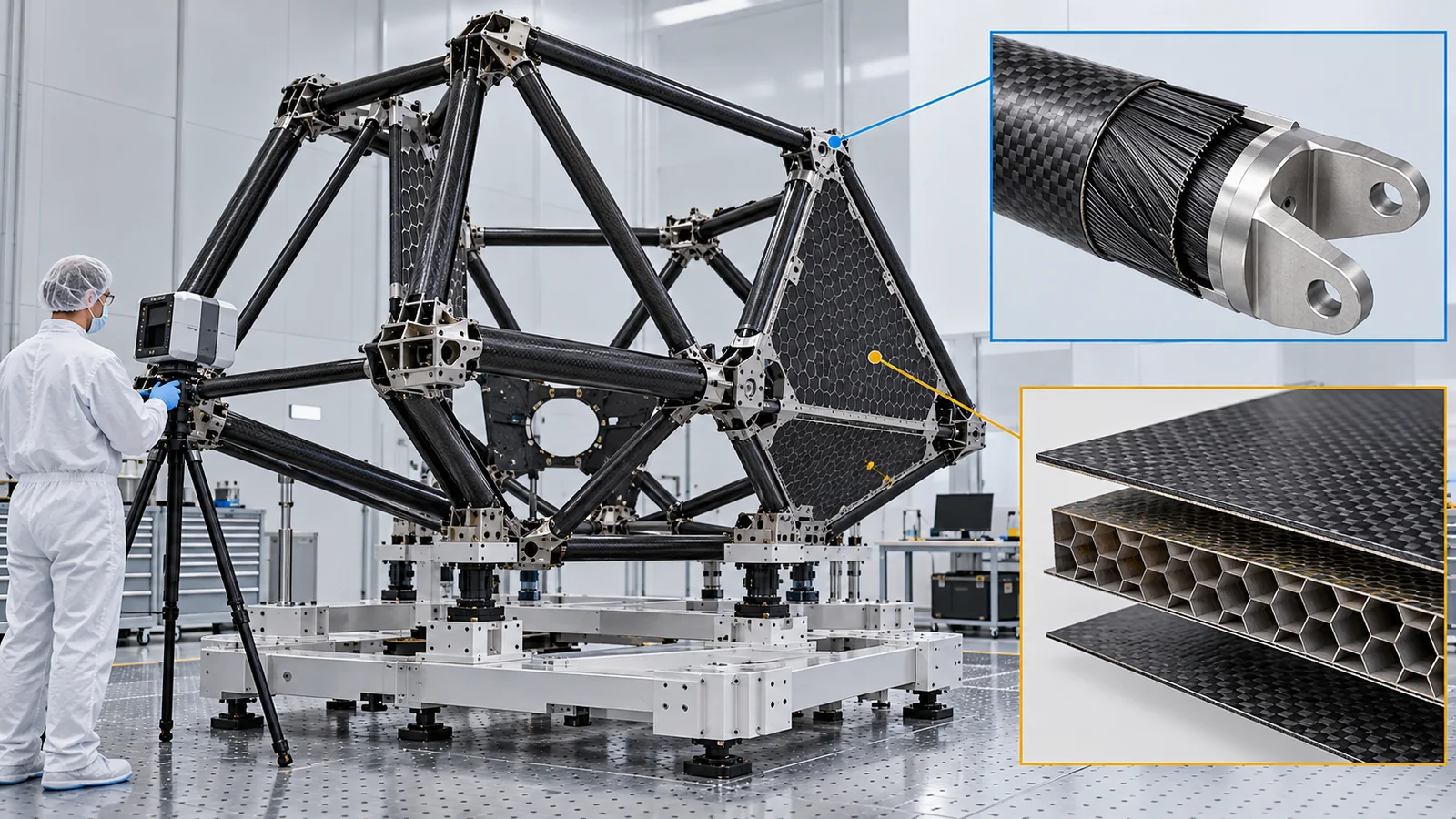
Carbon-fiber composites (CFRP) are light, stiff, and, in some directions, barely change size with temperature. In space they are used, or have been tried, in rocket fairings and interstages, telescope structures, pressure vessels and liquid-hydrogen tanks. Written for materials engineers who know little about space engineering, this article leaves the basics of CFRP to another article (the CFRP and composite materials explainer in the polymers series) and focuses on what is specific to space: dimensional stability, outgassing in vacuum, degradation in the orbital environment (atomic oxygen, thermal cycling, radiation), and the failure and demonstration of cryogenic tanks, all through primary sources such as NASA.
- The short version / what to know first / where this fits
- Where CFRP is used in space
- Dimensional stability: near-zero thermal expansion
- Giving off in vacuum: outgassing
- The orbital environment: atomic oxygen, thermal cycling, radiation
- Cryogenic tanks: the X-33 failure and NASA's demonstration
- Seams and pressure vessels
- How to read the yardsticks and standards / glossary / references / claim-to-source audit
Sourced = stated in a published source (linked)
Our calculation = a value this article calculated from stated assumptions
Not yet confirmed = company targets, plans, drafts of standards, and other items not yet settled
Our own reading for materials engineers is marked as commentary. Inference is shown in bold. Every analogy comes with a note on where it stops working.
Values of thermal expansion, strength and mass depend on the material pairing, layup, temperature range and test conditions. The values here carry the conditions of NASA reports and values under different conditions are not ranked. Fig. 3 is an explanatory value we calculated. On-orbit data carry the duration, altitude and specimen conditions and are separated from ground-test values. Failures are described neutrally within official investigations and statements, and causes are not asserted by inference. Check date: 17 October 2026. Military applications are not covered.
1. The short version, what to know first, and where this fits
- For space CFRP the selling point is less lightness than not changing size. NASA says Hubble, JWST and WFIRST rely on CFRP structures designed for high stiffness and near-zero thermal expansion; a quasi-isotropic laminate measured a mean of about −0.3 ppm/K.Sourced[Ref. 6]
- Vacuum and orbit are quiet enemies. Resin gives off gas (outgassing) that can contaminate optics,Sourced[Ref. 13] and in orbit atomic oxygen, thermal cycling and radiation cause erosion and microcracking.Sourced[Refs. 10, 11]
- Cryogenic tanks are the hardest test for composites. The X-33 composite liquid-hydrogen tank failed after microcracks let hydrogen into the core.Sourced[Ref. 15] NASA later changed the design and tested an all-composite liquid-hydrogen tank 5.5 m in diameter.Sourced[Ref. 17]
No space knowledge is needed. It is enough to know that CFRP is carbon fiber set in resin and that thermal expansion is how much a material changes size with temperature. For the basics of fiber, resin and forming, see the CFRP and composite materials explainer in the polymers and resins series; this article does not repeat it.
It is easier after the series overview and "space environment and materials" (the "five enemies" of space). Lightweight metals are in lightweight structural materials, polyimides in polyimides for space, spacecraft thermal management in spacecraft thermal control, liquid hydrogen in liquid hydrogen, and metal 3D printing in additive manufacturing for space.
2. Where CFRP is used in space
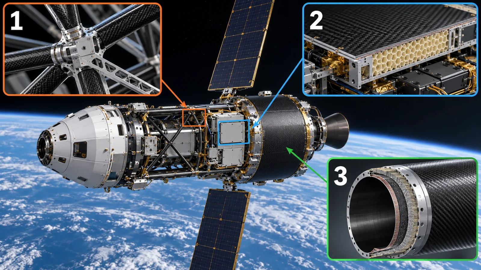
SpaceX says the Falcon 9 fairing (the cover that encloses a satellite during launch) is made of carbon composite and that the interstage joining first and second stages is a composite structure.Sourced[Ref. 1] (company statement). ESA describes the Vega first stage P80 as the largest one-piece carbon-fiber solid-propellant motor in the industry.Sourced[Ref. 2] NASA has published studies of composite interstage and shroud structures for SLS aimed at lower mass and cost.Sourced[Refs. 5, 4]
View original SVG, values and sources
Original SVG reference: Conceptual diagram (vector drawing). A map of where carbon-fiber composites are used in space. Each example is from the references of the text.
These examples share a pattern. In rocket structures, composites began with parts that do not face cryogenic temperatures or hot gas, such as interstages and fairings. NASA's study positions the interstage and shroud as simple structures without extreme environments (cryogenic or hot gas) and a good starting point for flying composites on a human-rated vehicle.Sourced[Ref. 5] Cryogenic tanks, by contrast, are the hardest application for composites (Section 5).
NASA also compared ways to build an interstage. Comparing a hat-stiffened structure (stiffeners with a hat-shaped cross-section) with a honeycomb sandwich structure by compression strength after impact damage, both had about the same strength once weight was factored in. The difference was that the hat-stiffened specimens failed in stages while the honeycomb sandwich failed catastrophically.Sourced[Ref. 3]
3. Dimensional stability: near-zero thermal expansion
In a space telescope, a displacement of micrometers (a few percent of the width of a human hair) between mirror and instruments blurs the image. A 2019 NASA Goddard paper says optical dimensional-stability requirements for space observatories are often in the micrometer range.Sourced[Ref. 6] And in space, temperatures swing between sunlight and shade, and JWST's instruments work at about 35 K (about −238 °C).Sourced[Ref. 7] Here not changing size with temperature becomes the most important property of a structural material.
NASA's paper says Hubble, JWST and WFIRST rely on carbon-fiber-reinforced polymer structures for designs of high stiffness and near-zero coefficient of thermal expansion (CTE). Almost without exception they pair PAN-based high-modulus fibers (such as Toray's M55J) with cyanate ester resins that absorb little water (such as TenCate's RS3 or Hexcel's 954).Sourced[Ref. 6] A prepreg of M55J 6K tow with RS3C has, per TenCate's stated values, a fiber-direction tensile strength of 1,999 MPa and tensile modulus of 318.5 GPa (at 60% fiber volume, nominal cured ply thickness 0.137 mm) (company's stated values).Sourced[Ref. 6]
Now the measured thermal expansion. NASA Langley and Marshall measured quasi-isotropic laminates of M55J/RS3C (fibers stacked so that properties are similar in every direction): −0.3 ppm/K for hand layup and −0.4 ppm/K for automated fiber placement (AFP) at Langley (room-temperature processing), and −0.2 to −0.3 ppm/K for Marshall AFP laminates.Sourced[Ref. 6] One ppm/K means a 1 m member changes length by 1 µm per kelvin.
For comparison, using the NIST linear-expansion fit for aluminum 6061-T6, the mean linear expansion coefficient over 80 to 300 K is about 18.3 ppm/K.Our calculation[Ref. 9] Cooling a 1 m member from 300 K to 80 K shrinks aluminum by about 4.0 mm, while the CFRP (an estimate applying −0.3 ppm/K over 220 K) grows slightly by about 0.07 mm.Our calculation The ratio is about 61.Our calculation
Thermal expansion is set by fiber, resin and layup. The −0.3 ppm/K above is a value for a plate with high-modulus fiber and a quasi-isotropic layup, designed for near-zero expansion. Perpendicular to the fibers expansion generally differs greatly and the resin expands a lot (general remark; our commentary), so a wrong layup lets even CFRP change size. This is why NASA built, for the JWST structure, an analysis model with temperature-dependent coefficients and stiffness and validated it in cryogenic tests.Sourced[Ref. 7]
For metals, choosing the material fixes the thermal expansion. For CFRP, near-zero expansion is obtained only by designing fiber direction and stacking order. And changing the manufacturing method, as with automated fiber placement, can break the high-modulus fibers and change stiffness and expansion. NASA's study reported that warming the material during processing reduced process-induced fiber breakage and gave stiffness and expansion consistent with hand layup.Sourced[Ref. 6] The manufacturing process is part of the property (our commentary).
4. Giving off in vacuum: outgassing
In vacuum, polymers such as resins, adhesives and paints release trapped water and low-molecular-weight components as gas. This is outgassing. The gas can condense on cold optical surfaces or sensors and fog them, which is fatal for observing instruments. ECSS publishes ECSS-Q-ST-70-02C, a thermal-vacuum standard for screening materials by outgassing. The test heats a specimen in a vacuum chamber, condenses what comes off onto a cool collector plate and measures the masses.Sourced[Ref. 13]
ECSS-Q-ST-70-02C defines three quantities. TML (total mass loss) is the fraction of mass the specimen lost; CVCM (collected volatile condensable material) is the fraction condensed on the collector plate; WVR (water vapor regained) is the water vapor taken up again in air after the test. The mass loss without water, RML, is TML − WVR. The minimum screening guide for selecting materials is RML below 1.0% and CVCM below 0.10%; the standard also says limits can be stricter for materials used in or near optical devices.Sourced[Ref. 13] NASA Goddard maintains a database of material outgassing data (TML, CVCM, WVR) from tests following ASTM E595 (Total Mass Loss and Collected Volatile Condensable Materials from Outgassing in a Vacuum Environment).Sourced[Ref. 14]
Resins absorb water from air. In vacuum that water leaves, but on many spacecraft water is not seen as a critical contaminant, which is why ECSS introduced the water-free RML. Where cryogenic equipment (−100 °C or below) is nearby, however, water too condenses and becomes a problem, so acceptance is judged separately.Sourced[Ref. 13] That absorbing moisture and desorbing it in vacuum can also affect structural dimensions is another point for materials engineers (general remark; numerical primary data could not be confirmed here).
5. The orbital environment: atomic oxygen, thermal cycling, radiation
Of the "five enemies" of materials in space, atomic oxygen in low orbit, repeated heating and radiation act on the resin of CFRP. NASA's LDEF (Long Duration Exposure Facility) was placed in low orbit at 482 km on 7 April 1984 and over about 5.8 years until retrieval on 12 January 1990 its orbit fell to 340 km, where atomic oxygen concentrations are higher.Sourced[Ref. 10] In its composites experiment (M0003-10), graphite-reinforced specimens with epoxy, polysulfone and polyimide matrices, prepared by Boeing, were tested after return. Specimens on the leading-edge face were eroded by atomic oxygen, and microcracking was found in specimens that were not unidirectionally reinforced.Sourced[Ref. 10]
Microcracks become more likely from the combination of thermal cycling and radiation. A NASA Langley ground study exposed a toughened epoxy/graphite composite to radiation doses equal to 6 months to 30 years in geosynchronous orbit and reported that the resin embrittles from about 10⁷ rad, thermal expansion changes, and significant microcracking appears in thermal cycling, which could limit service life.Sourced[Ref. 11] Another study reported that the high-modulus P75/930 (a lower-cure-temperature epoxy) degraded strongly under electron radiation above 10⁸ rad and thermal cycling between −250 °F and 150 °F, and was no better against microcracking than P75/934 with a standard cure temperature.Sourced[Ref. 12]
Microcracks change not only strength but thermal expansion and the movement of water and gas in vacuum (Sykes et al. report changes in thermal expansion together with microcracking).Sourced[Ref. 11] On the other hand, a NASA measurement found that a quasi-isotropic laminate kept a very small CTE even after cracking.Sourced[Ref. 6] How cracking affects dimensions depends on layup, material and environment and must be confirmed by testing.
6. Cryogenic tanks: the X-33 failure and NASA's demonstration
If liquid-hydrogen tanks could be made of composites, they might be much lighter than aluminum-lithium tanks (the NASA paper in Section 7 says 30 to 40%). But composite cryogenic tanks have a history of failure.
(1) The X-33 liquid-hydrogen tank
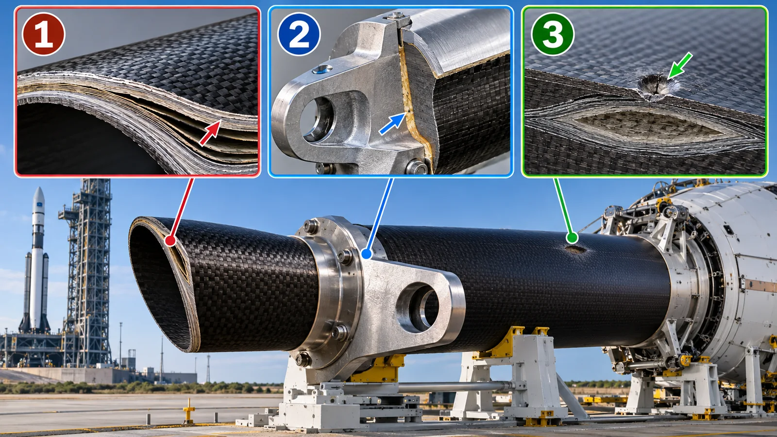
X-33 was a flight demonstrator for reusable spaceplane technology. Its liquid-hydrogen tank was a four-lobe sandwich structure of IM7/977-2 graphite/epoxy skins and a Korex honeycomb core (1.5 in thick) bonded with adhesive (AF-191).Sourced[Ref. 15] The tank already had problems during fabrication: after being placed in the autoclave for a repair, the skins of lobe 1 had separated from the core over a wide area. Inspection showed places where the adhesive fillets into the honeycomb were inadequate.Sourced[Ref. 16]
In the later pressure test the tank failed. NASA's investigation team summarized the most probable cause as a combination of factors: microcracking of the inner facesheet let hydrogen into the core; nitrogen purge gas entered the core by cryopumping through the outer facesheet and other areas; nitrogen and hydrogen raised core pressure above expectation; the core bond strength and toughness were lower than expected; and a piece of PTFE tape about 0.5 in by 2 5/8 in at the bondline created the critical debond area.Sourced[Ref. 15]
What stands out to a materials engineer is the stress calculation in the NASA presentation. The stress transverse to the fibers inside a ply of the inner facesheet was calculated at 14.3 ksi in the 90° plies: 10.1 ksi of thermal stress for a temperature change of −743 °F plus 4.2 ksi from pressure. The 90° tensile strength of this material (IM7/977-2) was, in tests, 10.4 to 12.4 ksi at room temperature and 5.7 to 9.3 ksi at −423 °F.Sourced[Ref. 15] The calculated stress exceeds the strength, especially at cryogenic temperature, so microcracks form: that was the conclusion of the presentation's microcrack analysis.
Carbon fiber and resin differ greatly in thermal expansion. When a laminate is cured hot and cooled to liquid-hydrogen temperature, large tensile stress transverse to the fibers is left in the resin within each ply. On X-33 it exceeded the transverse strength of the resin at cryogenic temperature. To prevent microcracks one can toughen the resin, use thinner plies or change the layup (our commentary). NASA's next demonstration used thin-ply prepreg (next subsection).
(2) NASA's next demonstration: CCTD
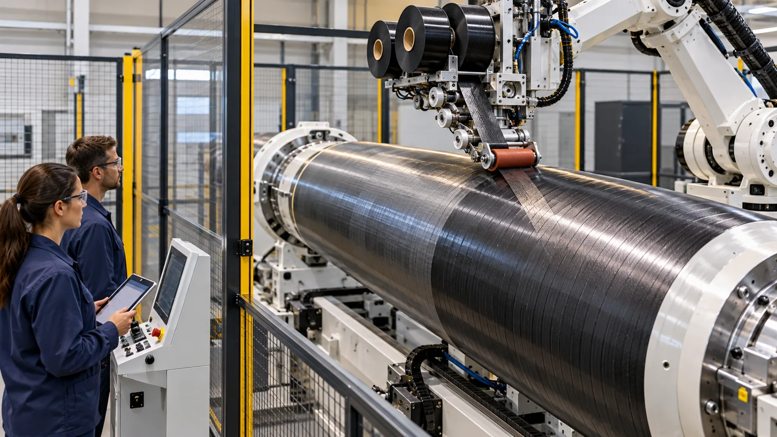
In NASA's Composite Cryotank Technologies and Demonstration (CCTD) project, Boeing was awarded a contract in September 2011 to design, manufacture and test two lightweight composite cryogenic tanks. The material was IM7 carbon fiber with CYCOM 5320-1 epoxy, a resin that cures without an autoclave, laid by automated fiber placement.Sourced[Ref. 18] Thin-ply prepreg to cut hydrogen permeation through the wall, a one-piece wall, a Y-joint to ease stress concentration, a fluted core allowing venting and purging, and ultrasonic inspection with structural health monitoring were included.Sourced[Ref. 17]
The 2.4 m tank met requirements in a test at NASA Marshall on 25 June 2013: filled with liquid hydrogen (−423 °F) to 90% volume, pressurized to 135 psig, and cycled 20 times while hydrogen permeation at the dome was measured. The 5.5 m tank arrived on 26 March 2014 and was filled with about 30,000 gal of liquid hydrogen, cycled repeatedly between 20 and 53 psi, and given structural loads.Sourced[Ref. 18] NASA calls the 5.5 m tank the largest automated-fiber-placement, out-of-autoclave composite liquid-hydrogen tank designed, manufactured and tested, and says the technology could offer 30 to 40% weight savings and substantial cost savings against aluminum-lithium tanks.Sourced[Refs. 17, 18]
What this article could confirm goes only as far as ground demonstration tests. The 30 to 40% weight savings is a potential stated in a NASA paper, not a value achieved on a flying vehicle. An upgrade of the SLS upper stage is cited as a potential first target,Sourced[Ref. 18] but adoption for flight could not be confirmed as of the check date. The weight and cost savings also depend on vehicle design and production volume.
7. Seams and pressure vessels
Composites share a tendency to fail not in the strength of the material but at seams between materials. Examples are the core-to-skin bond of X-33, the metal-to-composite bonded joints of JWST, and the boundary between metal liner and fiber in a COPV.
View original SVG, values and sources
Original SVG reference: Conceptual diagram (vector drawing). Weak points of composites: sandwich bonds, joints to metal, and pressure vessels with metal liners. Each item is from NASA reports.
The JWST ISIM structure is a large bonded composite frame that keeps position between telescope and instruments. Because thermal distortion directly affects instrument alignment, NASA Goddard tested step by step from material tests (stiffness, strength, CTE) through basic joints and subassemblies to flight hardware, and validated a high-fidelity analysis model using temperature-dependent coefficients and stiffness (over 2 million degrees of freedom for the flight structure).Sourced[Ref. 7] The design and analysis of metal-to-composite bonded joints surviving cryogenic temperatures are reported separately.Sourced[Ref. 8]
A composite overwrapped pressure vessel (COPV) wraps a thin metal liner in fiber and resin and is lighter than an all-metal design.Sourced[Ref. 21] A NASA independent assessment (NESC) examined the limits of predicting the growth of small liner cracks and set out test methods to validate damage tolerance.Sourced[Ref. 19] NASA White Sands ran a six-year program of stress-rupture tests (failure over time at a held pressure) on Kevlar COPVs to gather data for life prediction.Sourced[Ref. 21] Research also exists on equations that separate a small hole from tank rupture on orbital-debris impact.Sourced[Ref. 20]
On X-33, a foreign object at the bondline became the critical debond area. The CCTD tanks included ultrasonic inspection and structural health monitoring to detect impact damage.Sourced[Refs. 15, 17] In composites, defects between layers and at bondlines are invisible from outside. For materials engineers, how small a defect can be detected drives the design safety factor and decides where a composite can be used (our commentary).
8. How to read the yardsticks and standards
Composites for space are assessed on dimensional stability (thermal expansion), outgassing, degradation in the orbital environment, strength, toughness and damage tolerance, cracking and hydrogen permeation at cryogenic temperature, and bond and joint quality. No single number decides; read each with its layup and temperature range.
| What is assessed | Typical test or method (name, source) | Standards and guidance (ECSS, NASA, etc.) | Reading notes |
|---|---|---|---|
| Dimensional stability (thermal expansion) | Laminate CTE measurement (NASA Goddard, including cryogenic) and thermal-distortion analysis with stepwise validation (JWST ISIM).Sourced[Refs. 6, 7] | Could not be confirmed (a standard for CTE measurement was not checked). Design references: ECSS-E-HB-32-20 Part 1A and CMH-17.Sourced[Refs. 22, 25] | Mean coefficients vary with temperature range, layup, and fiber breakage. |
| Outgassing | Thermal-vacuum test measuring TML, CVCM and WVR; the NASA Goddard database follows ASTM E595.Sourced[Refs. 13, 14] | ECSS-Q-ST-70-02C (15 November 2008): RML below 1.0% and CVCM below 0.10% as the minimum guide.Sourced[Ref. 13] | Stricter near optics. Meeting the limits does not guarantee a contamination-free spacecraft (same standard). |
| Degradation in the orbital environment | On-orbit exposure (LDEF) and ground radiation and thermal-cycling tests (Langley).Sourced[Refs. 10, 11, 12] | Could not be confirmed (an international standard for assessing orbital exposure was not checked). Materials and processes selection: ECSS-Q-ST-70-71C Rev.1 (15 October 2019) and NASA-STD-6016.Sourced[Refs. 26, 27] | Dose and oxygen flux differ with orbit, altitude, duration and shielding. Results carry specimen conditions. |
| Strength, toughness, damage tolerance | Compression after impact (interstage comparison) and COPV damage-tolerance tests (NESC).Sourced[Refs. 3, 19] | CMH-17 (a handbook whose purpose is standardizing methodologies for testing, data reduction and reporting of composite property data).Sourced[Ref. 25] | Design allowables are set per material, process and lot, and differ from typical values. |
| Cryogenic tanks (cracking, permeation) | Pressure and thermal cycling tests with liquid hydrogen with permeation measurements (CCTD) and failure investigation (X-33).Sourced[Refs. 17, 15] | Could not be confirmed (a common standard for composite cryogenic tanks was not checked). | Ground demonstration differs from flight heritage. |
| Bonding and inserts | Bond fracture-toughness tests (X-33 investigation) and stepwise tests of metal-to-composite joints (JWST).Sourced[Refs. 15, 7] | ECSS-E-HB-32-21A "Adhesive bonding handbook" and ECSS-E-HB-32-22A "Insert design handbook" (both 20 March 2011; handbooks).Sourced[Refs. 23, 24] | Handbooks are design references, not requirements. |
| Pressure vessels (COPV) | Stress-rupture tests, damage-tolerance tests and impact-limit equations.Sourced[Refs. 19, 20, 21] | Could not be confirmed (the number, title and status of a dedicated COPV standard were not checked). | Treatment of small liner cracks is the crux of damage tolerance. |
| ASTM standards | A NASA Goddard page mentions use of ASTM E595 for outgassing.Sourced[Ref. 14] | Other relevant ASTM standards were not checked (the ASTM website was not opened). The number and use follow the NASA page. | — |
The arrangement of the table is Our calculation (organizing). Numbers, titles and status were checked on ecss.nl (17 October 2026). Of the standards only the text of ECSS-Q-ST-70-02C was read; for the others only titles and scope are given.
Reading notes (for materials engineers)
- Ground tests and orbital records differ. CTE measurements were made in laboratories on specific laminates. LDEF is 5.8 years of real exposure but carries specimen and location conditions.
- Manufacturer-stated values differ from independent measurements. The strength and modulus of M55J/RS3C are TenCate's stated values and the CTE is NASA's measurement; do not compare them as one table.
- Check whether a standard is a recommendation or a requirement. The criteria of ECSS-Q-ST-70-02C become requirements when a project adopts them by contract. ECSS-E-HB documents are handbooks, not requirements.
- Plans and achievements differ. The weight savings of composite cryogenic tanks are a potential stated in a NASA paper, not an achievement in flight.
9. Glossary
- CFRP
- Carbon-fiber-reinforced polymer.
- Prepreg
- Fiber sheet pre-impregnated with resin.
- Cyanate ester
- A resin that absorbs little water and gives little contamination; used in observatory structures.
- M55J
- A PAN-based high-modulus carbon fiber (Toray).
- CTE (coefficient of thermal expansion)
- The fractional change of length per kelvin, in ppm/K.
- Quasi-isotropic laminate
- A laminate with fiber directions staggered so in-plane properties are similar in every direction.
- Automated fiber placement (AFP)
- A forming method that lays fiber tape with a robotic head.
- ISIM
- Integrated Science Instrument Module of JWST.
- Outgassing
- Release of gaseous components from a material in vacuum.
- TML / CVCM / WVR / RML
- Total mass loss / collected volatile condensable material / water vapor regained / recovered mass loss.
- Bake-out
- Heating hardware to drive out remaining contaminants and water.
- LDEF
- Long Duration Exposure Facility, NASA's long-duration exposure experiment (1984 to 1990).
- Atomic oxygen
- Oxygen atoms abundant in low orbit; they erode polymers.
- Microcrack
- A tiny crack in the resin.
- Sandwich structure / honeycomb
- Thin skins around a light core such as honeycomb.
- Fillet
- The bead of adhesive that builds up at a corner or edge.
- Cryopumping
- Surrounding gas condensing onto and being drawn to a cryogenic surface.
- Autoclave
- A pressure oven that cures composites under heat and pressure.
- COPV
- Composite overwrapped pressure vessel: a metal liner wrapped in fiber.
- Stress rupture
- Failure over time under a constant stress.
- CCTD
- Composite Cryotank Technologies and Demonstration, NASA's composite cryotank project.
- CMH-17
- A handbook aimed at standardizing composite data and test methods.
- ECSS
- European Cooperation for Space Standardization.
10. References
- SpaceX "Falcon 9" (vehicle page: composite interstage, carbon-composite fairing) (company statement; checked 17 October 2026) — www.spacex.com/vehicles/falcon-9/
- ESA "Vega" (launch vehicle page: P80 first stage) (checked 17 October 2026) — www.esa.int/Enabling_Support/Space_Transportation/Launch_vehicles/Vega
- Nettles A. T. (NASA Marshall) "A Damage Tolerance Comparison of Composite Hat-Stiffened and Honeycomb Sandwich Structure for Launch Vehicle Interstage Applications" (2011) — ntrs.nasa.gov/citations/20110024205
- Mann T. et al. (NASA) "Sizing and Lifecycle Cost Analysis of an Ares V Composite Interstage" (2012) — ntrs.nasa.gov/citations/20120008842
- Nettles A., Nettles M. (NASA Marshall) "Composite Dry Structure Cost Improvement Approach" (2015) — ntrs.nasa.gov/citations/20160008012
- Segal K. N. et al. (NASA Goddard) "Automated Fiber Placement Manufactured Composites for Science Applications" (2019) — ntrs.nasa.gov/citations/20190000862
- Johnston J., Cofie E. (NASA Goddard) "An Overview of Thermal Distortion Modeling, Analysis, and Model Validation for the JWST ISIM Structure" (2011) — ntrs.nasa.gov/citations/20110011002
- Johnston J. D. et al. (NASA Goddard) "Current Progress on the Design and Analysis of the JWST ISIM Bonded Joints for survivability at Cryogenic Temperatures" (2005) (only the abstract of the slides was checked) — ntrs.nasa.gov/citations/20050214585
- NIST "Cryogenic material properties: 6061-T6 Aluminum" (linear expansion fit) (checked 17 October 2026) — trc.nist.gov/cryogenics/materials/6061%20Aluminum/6061_T6Aluminum_rev.htm
- George P. E. (Boeing) "Space environmental effects on LDEF low Earth orbit exposed graphite reinforced polymer matrix composites" (1992) — ntrs.nasa.gov/citations/19930001397
- Sykes G. F., Bowles D. E. (NASA Langley) "Space radiation effects on the dimensional stability of a toughened epoxy graphite composite" (1986) — ntrs.nasa.gov/citations/19870024573
- Funk J. G. (NASA Langley) "Effects of cure temperature, electron radiation, and thermal cycling on P75/930 composites" (1990) — ntrs.nasa.gov/citations/19910006019
- ECSS ECSS-Q-ST-70-02C "Thermal vacuum outgassing test for the screening of space materials" (15 November 2008) (text also checked; checked 17 October 2026) — ecss.nl/standard/ecss-q-st-70-02c-thermal-vacuum-outgassing-test-for-the-screening-of-space-materials/
- NASA Goddard "Outgassing Database" (Engineering and Technology Directorate) (database of TML, CVCM and WVR; checked 17 October 2026) — outgassing.nasa.gov/
- Glaessgen E. H. (NASA Langley) "Failure Analysis of the X-33 Liquid Hydrogen Composite Tank" (symposium presentation, 2012) — ntrs.nasa.gov/citations/20200006023
- Nettles A. T., Munafo P. (NASA Marshall) "X-33 Tank Failure During Autoclave Fabrication" (2001) — ntrs.nasa.gov/citations/20020021989
- Jackson J. R. et al. (NASA) "Composite Cryotank Technologies and Development 2.4 and 5.5M out of Autoclave Tank Test Results" (2015) — ntrs.nasa.gov/citations/20150021410
- Vickers J. (NASA Marshall) "Composite Cryotank Technologies and Demonstration" (NASA Spinoff-style summary, 2015) — ntrs.nasa.gov/citations/20160008034
- Hickman H. K. et al. (NASA) "Composite Overwrapped Pressure Vessel (COPV) Damage Tolerance Life Analysis Methodology and Test Best Practices" (NESC, 2020) — ntrs.nasa.gov/citations/20205006765
- Schonberg W. (Missouri S&T) "A Compilation of Composite Overwrapped Pressure Vessel Research (2015-2021)" (2023) — ntrs.nasa.gov/citations/20230012105
- Greene N. et al. (NASA White Sands) "Overview of NASA White Sands Test Facility Composite Overwrapped Pressure Vessel Testing" (2006) — ntrs.nasa.gov/citations/20080031321
- ECSS ECSS-E-HB-32-20 Part 1A "Structural materials handbook – Part 1: Overview and material properties and applications" (20 March 2011) (a handbook; checked 17 October 2026) — ecss.nl/hbstms/ecss-e-hb-32-20-part-1a-structural-materials-handbook-part-1-overview-and-material-properties-and-applications-20-march-2011/
- ECSS ECSS-E-HB-32-21A "Adhesive bonding handbook" (20 March 2011) (a handbook; checked 17 October 2026) — ecss.nl/hbstms/ecss-e-hb-32-21a-adhesive-bonding-handbook/
- ECSS ECSS-E-HB-32-22A "Insert design handbook" (20 March 2011) (a handbook; checked 17 October 2026) — ecss.nl/hbstms/ecss-e-hb-32-22a-insert-design-handbook/
- CMH-17 "Composite Materials Handbook-17" (CMH-17 website) (the description of the handbook's purpose was checked; checked 17 October 2026; membership needed for parts) — www.cmh17.org/
- ECSS ECSS-Q-ST-70-71C Rev.1 "Materials, processes and their data selection" (15 October 2019) (checked 17 October 2026) — ecss.nl/standard/ecss-q-st-70-71c-rev-1-materials-processes-and-their-data-selection-15-october-2019/
- NASA NASA-STD-6016 "Standard Materials and Processes Requirements for Spacecraft" (Version C with Change 1, change date 15 November 2023) (Active; checked 17 October 2026) — standards.nasa.gov/standard/NASA/NASA-STD-6016
11. Claim-to-source audit
| Claim in the text | Basis | Type |
|---|---|---|
| The Falcon 9 fairing (carbon composite) and interstage (composite structure) | SpaceX official page (company statement) Reference 1 https://www.spacex.com/vehicles/falcon-9/ | Sourced |
| The Vega first stage P80 being the largest one-piece carbon-fiber solid motor in the industry | ESA page Reference 2 https://www.esa.int/Enabling_Support/Space_Transportation/Launch_vehicles/Vega | Sourced |
| Composite interstage and shroud studies for SLS, the mass and cost outlook for a composite interstage, and the compression-after-impact comparison (hat-stiffened versus honeycomb sandwich) | NASA (Nettles et al., Mann et al.) Reference 5 https://ntrs.nasa.gov/citations/20160008012 Reference 4 https://ntrs.nasa.gov/citations/20120008842 Reference 3 https://ntrs.nasa.gov/citations/20110024205 | Sourced |
| Hubble, JWST and WFIRST relying on CFRP structures, PAN-based M55J with cyanate ester, optical dimensional-stability requirements, the stated strength and modulus of M55J/RS3C, laminate CTE (−0.3, −0.4 and −0.2 to −0.3 ppm/K), and the effect of AFP processing temperature | NASA Goddard and others (Segal et al., 2019) Reference 6 https://ntrs.nasa.gov/citations/20190000862 | Sourced |
| The JWST ISIM structure (a large bonded composite frame, instruments at about 35 K, stepwise thermal-distortion tests and model validation) and cryogenic design of metal-to-composite bonded joints | NASA Goddard (Johnston et al.) Reference 7 https://ntrs.nasa.gov/citations/20110011002 Reference 8 https://ntrs.nasa.gov/citations/20050214585 | Sourced |
| The linear-expansion fit for aluminum 6061-T6 (4 to 300 K) | NIST cryogenic material properties Reference 9 https://trc.nist.gov/cryogenics/materials/6061%20Aluminum/6061_T6Aluminum_rev.htm | Sourced |
| The purpose and definitions of the outgassing test (TML, CVCM, WVR, RML), the minimum guide of RML below 1.0% and CVCM below 0.10%, stricter limits for optics, handling of water, and bake-out | ECSS-Q-ST-70-02C (text checked) Reference 13 https://ecss.nl/standard/ecss-q-st-70-02c-thermal-vacuum-outgassing-test-for-the-screening-of-space-materials/ | Sourced |
| The NASA Goddard outgassing database following ASTM E595 tests | NASA Goddard page Reference 14 https://outgassing.nasa.gov/ | Sourced |
| LDEF (7 April 1984 at 482 km, retrieved 12 January 1990, about 5.8 years, falling to 340 km), and atomic-oxygen erosion and microcracking of composite specimens | NASA (George, 1992) Reference 10 https://ntrs.nasa.gov/citations/19930001397 | Sourced |
| Radiation effects on a toughened epoxy/graphite (embrittlement from about 10⁷ rad) and the degradation of P75/930 (above 10⁸ rad, −250 to 150 °F) | NASA Langley (Sykes et al., Funk) Reference 11 https://ntrs.nasa.gov/citations/19870024573 Reference 12 https://ntrs.nasa.gov/citations/19910006019 | Sourced |
| The construction of the X-33 liquid-hydrogen tank, the hypothesized failure sequence and most probable cause, the stress calculation (14.3 ksi) and transverse strength, the PTFE tape, and inadequate adhesive fillets during fabrication | NASA (Glaessgen, 2012; Nettles and Munafo, 2001) Reference 15 https://ntrs.nasa.gov/citations/20200006023 Reference 16 https://ntrs.nasa.gov/citations/20020021989 | Sourced |
| CCTD materials, design and tests (2.4 m on 25 June 2013; 5.5 m arriving 26 March 2014), the 30 to 40% weight-saving potential, and the SLS upper-stage candidate | NASA (Jackson et al., 2015; Vickers, 2015) Reference 17 https://ntrs.nasa.gov/citations/20150021410 Reference 18 https://ntrs.nasa.gov/citations/20160008034 | Sourced |
| The structure and advantage of COPVs, the NESC damage-tolerance assessment, stress-rupture tests and impact-limit equations | NASA (Hickman et al., Greene et al., Schonberg) Reference 19 https://ntrs.nasa.gov/citations/20205006765 Reference 20 https://ntrs.nasa.gov/citations/20230012105 Reference 21 https://ntrs.nasa.gov/citations/20080031321 | Sourced |
| Numbers, titles, dates and status of ECSS-E-HB-32-20 Part 1A, -32-21A, -32-22A, ECSS-Q-ST-70-71C Rev.1 and NASA-STD-6016, and the purpose of CMH-17 | ECSS, NASA Technical Standards System, CMH-17 site Reference 22 https://ecss.nl/hbstms/ecss-e-hb-32-20-part-1a-structural-materials-handbook-part-1-overview-and-material-properties-and-applications-20-march-2011/ Reference 23 https://ecss.nl/hbstms/ecss-e-hb-32-21a-adhesive-bonding-handbook/ Reference 24 https://ecss.nl/hbstms/ecss-e-hb-32-22a-insert-design-handbook/ Reference 26 https://ecss.nl/standard/ecss-q-st-70-71c-rev-1-materials-processes-and-their-data-selection-15-october-2019/ Reference 27 https://standards.nasa.gov/standard/NASA/NASA-STD-6016 Reference 25 https://www.cmh17.org/ | Sourced |
| Dimensional change of a 1 m member cooled from 300 to 80 K (about 4.0 mm shrink for aluminum, about 0.07 mm growth for CFRP), the mean linear expansion of about 18.3 ppm/K, and the ratio of about 61 | Our calculation (NIST fit and the mean coefficient of a NASA measurement; CFRP is an estimate applying it over 220 K) | Our calculation |
| A standard for CTE measurement, numerical effects of moisture absorption and desorption on dimensions, flight adoption of composite cryogenic tanks, a dedicated COPV standard, ASTM standards other than E595, and an international standard for orbital exposure | Could not be confirmed in primary sources within this survey, so not stated (this article) | Commentary |
| The readings "zero expansion is a design of the structure", "the process is part of the property", "microcracks and dimensional stability", "thermal stress inside the ply", "inspectability shapes use", "failure at seams", and analogies and their limits | Our organization and commentary based on the published material | Commentary |
| Figs. 1 and 9 are AI-generated concept images, and Figs. 2 to 8 are explanatory drawings | Note by this article | Commentary |
Last updated: 17 October 2026. Sources are limited to primary materials (NASA reports and presentations, ESA, ECSS standard and handbooks, NIST, an official SpaceX page). Company announcements are treated as company statements. The numerical example (thermal-expansion comparison) is an explanatory calculation made for this article. A standard for CTE measurement, numerical effects of moisture absorption and desorption on dimensions, flight adoption of composite cryogenic tanks and a dedicated COPV standard could not be confirmed and are not stated. The X-33 cause is the combination of factors the NASA team judged "most probable", not a certainty. Figs. 1 and 9 are AI-generated concept images and do not depict real facilities or products.