TECHNOLOGY EXPLAINER
Polyimides for Space
— How the gold-colored film holds up against vacuum, oxygen atoms and radiation
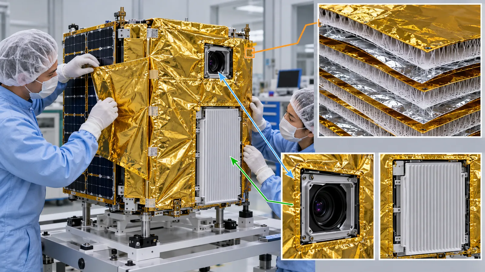
The gold film wrapped around spacecraft, the base of bendable wiring, the thin substrate of lightweight solar arrays: much of it is polyimide. On the ground it is known as a tough, heat-resistant film, but in orbit it faces a different set of tests. Vacuum draws water out of it; in low orbit it is slowly eroded by oxygen atoms; ultraviolet light and radiation tint it and make it brittle; and used as wire insulation, a nick can let an arc run along the harness. This article is written for materials engineers who know little about spaceflight. With figures and a few small calculations, it walks through what polyimide goes through in space, and it keeps three things apart: what was measured, what we calculated, and what we could not confirm.
- The short version / what to know first / where this fits in the series
- Background: low Earth orbit and the "five enemies"
- Where polyimide is used
- Enemy 1, vacuum: water comes out (outgassing)
- Enemy 4, atomic oxygen: the surface is eroded in low orbit
- Defenses: placement, layering, coatings and material design
- Enemy 2, UV and radiation: tinting and brittleness
- What happens in wire insulation: arc tracking
- Colorless polyimide and the solar sail
- Limits, and what could not be confirmed
- How to read the yardsticks and standards
- Glossary / References / Claim-to-source audit
Sourced = stated in published material (link given)
Our calculation = a value this article worked out from stated assumptions
Not yet confirmed = plans, drafts or targets that are not settled
Readings for the materials field are marked as commentary. Inference is shown in bold. Every analogy comes with its limit.
The "time for a film to erode away" in Chapter 5 and the RML values in Chapter 4 are illustrative values we calculated. Flight measurements (erosion yield and so on) are values under the conditions in the NASA reports (outside the International Space Station, about four years) and do not carry over to another orbit, orientation or year. Results of ground simulations are not values measured in real space. Manufacturer values are labeled as the manufacturer's, and for standards we only checked titles, scope and status. Because this field changes fast, standards carry a checking date (17 October 2026).
1. The short version / what to know first / where this fits in the series
- The gold film is a spacecraft's "blanket, wiring and substrate": thin polyimide film coated with aluminum is stacked into multilayer insulation (MLI), and it is also the base of bendable circuits and thin solar-array substrates Sourced[Ref. 3, 5, 9]
- The enemies narrow down to three: (1) vacuum draws out water and other gases; (2) in low orbit, oxygen atoms (atomic oxygen) erode the surface; (3) ultraviolet light and radiation tint the film and make it brittle. NASA flight experiments report an erosion yield of 3.0 × 10⁻²⁴ cm3 per atom for the reference polyimide (Kapton H), and under one set of conditions this works out to a 25 µm film being gone in a few months SourcedOur calculation[Ref. 1]
- Defense is not only "change the material": put a sacrificial layer outside, deposit metal, add a coating, redesign the polymer, and then confirm by testing. For wires, designers also look at behavior after the insulation is damaged, not only normal performance Sourced[Ref. 3, 13, 8]
The synthesis of polyimide itself (the two-step route), the properties of Kapton and the reasons colorless versions are hard to make are covered in our explainer on polyimides (in the polymers and resins field). We do not repeat them here. Space terms are explained where they appear. If "orbit", "low orbit" and "vacuum" are still hazy, Chapter 2 sums them up.
This is one of the materials articles in the Space Industry series. Reading our explainer on the space environment and its effects on materials first gives the whole picture of the five enemies. How MLI works and how a spacecraft sheds heat are covered in our explainer on spacecraft thermal control, and how less heat-resistant plastics such as PEEK are used in space is covered in our explainer on super engineering plastics for space.
2. Background: low Earth orbit and the "five enemies"
First, where does polyimide actually sit? Why do satellites and the International Space Station (ISS) not fall to the ground?
The answer is that they keep falling, but move sideways fast enough that they never hit the ground. Imagine firing a cannonball sideways, faster and faster. Beyond a certain speed it moves on over the curve of the Earth before it can land. That is an orbit (Newton's thought experiment). Where the analogy breaks down: in reality a thin atmosphere drags on the craft and uneven gravity nudges it, so real orbits drift slowly.
NASA reports that the ISS flies at an altitude of about 400 km at roughly 7.7 km per second Sourced[Ref. 1]. Assuming a circular orbit at 400 km, one lap takes about 92 minutes, or about 15 to 16 laps a day Our calculation. In other words, the craft passes between sunlight and shadow roughly every 90 minutes.
Take the Earth's radius as 6,371 km and the Earth's gravitational parameter as 3.986 × 10⁵ km3/s2. The orbit radius is a = 6,371 + 400 = 6,771 km. The period is T = 2π√(a3/μ) = 2π√(6,7713/398,600) ≈ 5,540 s ≈ 92.4 minutes. The speed is √(μ/a) ≈ 7.67 km/s, which agrees with the 7.7 km/s in the NASA report. Per day (1,440 minutes), that is 1,440 ÷ 92.4 ≈ 15.6 laps. Assumptions and limits: a textbook calculation for a circular orbit at constant altitude, not real orbital elements.
In this "low Earth orbit" (LEO), space is not "empty vacuum". Even near 400 km a very thin atmosphere remains, and its main component is the oxygen atom we meet below. This series organizes the space environment as five enemies. Polyimide meets all five in the figure below.
With no air to oxidize it and no moisture, a material might seem to last forever in vacuum. That is wrong. Low orbit is full of oxygen atoms that erode polyimide's surface. Ultraviolet light and radiation break polymer chains even in vacuum. And vacuum pulls out the water and other components the material had absorbed. Space is not a gentle, quiet place for materials; it is a place where kinds of stress that do not exist on the ground pile up.
3. Where polyimide is used
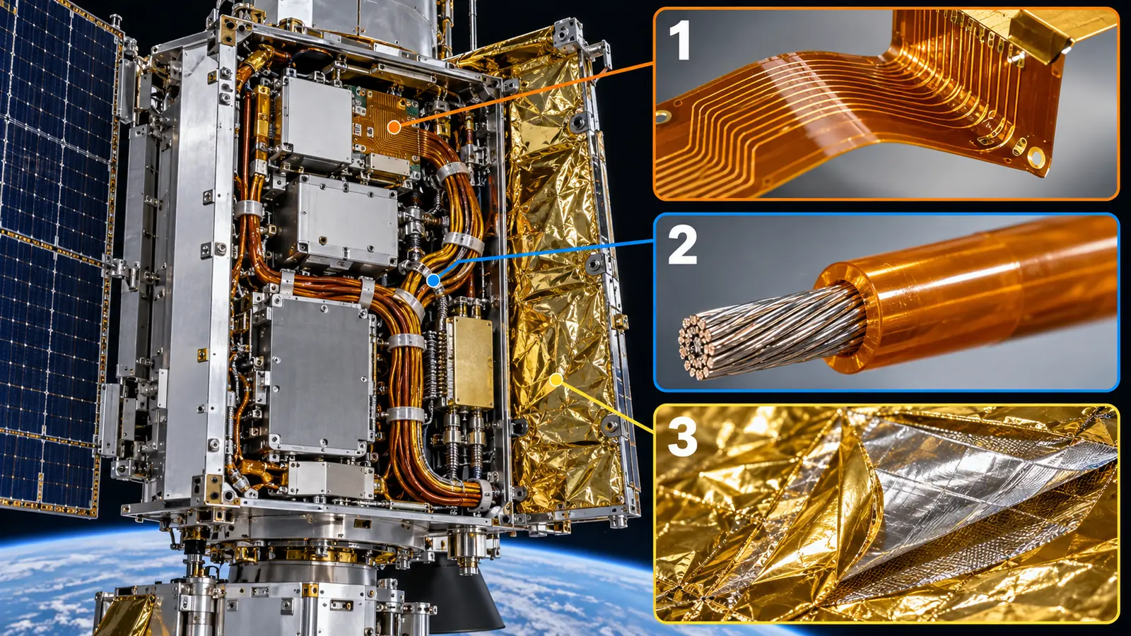
Polyimide is a thin, light, heat-resistant film. Primary sources confirm its use in the following places on spacecraft.
View original SVG, values and sources
Original SVG reference: Concept diagram (vector drawing). The main places where polyimide film is used inside a satellite. The layout is illustrative and does not show any specific satellite. The basis for each use is given in the table below.
| No. | Use | What the primary sources confirm | Main enemies |
|---|---|---|---|
| 1 | Multilayer insulation (MLI) | NASA report: tray F-9 of LDEF (a retrievable experiment satellite) was covered in MLI of aluminized Kapton. The outermost layer was 0.076 mm thick, with 15 layers of 0.0076 mm double-aluminized Kapton beneath it, separated by polyester net Sourced[Ref. 3]. The NASA database also holds records for MLI use Sourced[Ref. 5] | 4 atomic oxygen, 1 vacuum, 5 debris |
| 2 | Flexible circuits and heaters | The NASA outgassing database has records for a Kapton material whose application is "flexible circuit board" (gold-plated copper conductor with acrylic adhesive, 2003, record GSFC28414) and a Kapton product whose application is "heater" (1974, record GSFC06212) Sourced[Ref. 5] | 1 vacuum, 3 temperature swings |
| 3 | Solar-array substrates and stowage parts | A technique for coating Kapton H with a protective SiOx film as the substrate of the flexible solar array planned for Space Station Freedom (1991) Sourced[Ref. 14]. In the ISS solar-array blanket box, the Kapton covering the polyimide foam had degraded in orbit Sourced[Ref. 16]. IKAROS carried thin-film solar cells (25 µm thick) on a polyimide membrane (7.5 µm thick) Sourced[Ref. 9] | 4 atomic oxygen, 2 radiation |
| 4 | Wire insulation | A NASA Johnson test report (1990) states that Space Shuttle Orbiter wiring is predominantly Kapton-insulated Sourced[Ref. 24]. A 1994 presentation also deals with Kapton wire [Ref. 8] | Behavior after damage (Chapter 8) |
| 5 | Solar-sail membrane | JAXA: the IKAROS membrane was a square 20 m on the diagonal, made of polyimide 7.5 µm thick (pre-launch design values) Sourced[Ref. 9] | 2 radiation, UV |
| 6 | Adhesive tape and labels | The NASA database has a record for Kapton tape (3M Tape #1205, 2019) Sourced[Ref. 5] | 1 vacuum (the adhesive) |
The "main enemies" column is this article's organization of what the sources say (commentary). We did not check how much or what share of spacecraft polyimide is used in each place.
The outside face of MLI takes ultraviolet light and oxygen atoms head-on. The inner layers are shielded by the outer ones, so their job is mainly low weight, reflectivity and giving off little gas in vacuum. As the base of wiring, the job is heat, bending and insulation. Even for the "same" polyimide, what it will meet where it sits decides the choice more than catalog values such as tensile strength (commentary). Anyone who has handled films, substrates or varnishes on the ground will notice that space specifications have entries for "outgassing", "atomic oxygen" and "arcing".
4. Enemy 1, vacuum: water comes out (outgassing)
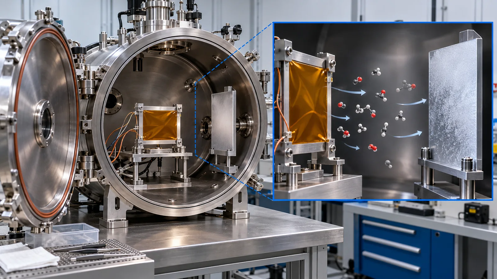
Start with the most familiar enemy. Polyimide readily absorbs moisture from air. When the craft reaches vacuum, the absorbed water turns to gas and leaves. Not only water: components of adhesives and plasticizers also come out. This is outgassing.
Why is that a problem? The released gas can condense on nearby cold surfaces (lenses, mirrors, sensor windows, solar-cell covers) and fog them or leave a film. So spacecraft materials go through outgassing tests in vacuum chambers on the ground.
What the test measures
NASA describes the outgassing test as measuring the mass lost in vacuum (total mass loss, TML) and the amount that left as gas and then condensed on a separate cold plate (CVCM). The test method is ASTM E 595 Sourced[Ref. 1, 5]. The European standard ECSS-Q-ST-70-02C defines a test on the same principle. Its conditions: condition the sample at (22 ± 3) °C and (55 ± 10) % relative humidity, then hold it in vacuum (10-3 Pa or lower) at 125 °C for 24 hours and weigh what condenses on a cooled collector at 25 °C Sourced[Ref. 4].
Think of a bath towel. Put a damp towel in a dryer and it gets lighter (TML: the total loss). Most of the loss is water. But leave it out for a while and it takes moisture back up and gets heavier (WVR: the water vapor regained). So "the part that really left, excluding water" is written RML = TML − WVR. Finally, the film that fogs the dryer's window is CVCM (what condensed). What fogs a window is usually oily stuff more troublesome than water. Where the analogy breaks down: in a spacecraft, the towel's water is not always harmless. Near a cold optical surface, water itself can be a problem (ECSS only allows treating water as non-critical under conditions).
As a screening guide, ECSS-Q-ST-70-02C gives RML < 1.0 % and CVCM < 0.10 % as the minimum screening values for selecting a material. It also says that a material from which water leaves quickly, such as polyimide film, may be accepted with a TML above 1.0 % if its RML is below 1.0 %, provided conditions are met (no equipment colder than -100 °C is involved, no high-voltage equipment is involved, and ground purging with dry gas controls water re-absorption) Sourced[Ref. 4].
The top four records in Fig. 4 (aluminized Kapton, black Kapton, an MLI laminate) have a TML of 0.54 to 1.34 %, and most of it is WVR (water). After removing water, the RML is only 0.02 to 0.21 %. Looking at TML alone, some exceed 1 % (1.08 and 1.34), so whether you judge by TML or by RML changes the verdict. The bottom two (Kapton tape with acrylic adhesive, and a Kapton/Kevlar laminate), by contrast, have an RML of 1.19 % and 2.67 % and a CVCM of 0.14 % and 0.28 % even after removing water, exceeding the guide values above. The records do not list what the adhesive or bonding layers contain, so the cause cannot be told from them. Inference: the adhesive or bonding-layer components may be responsible. Either way, the records show that a bare polyimide film and the same film after it has been bonded are judged differently (commentary). On the ground we look at film properties; in space, the whole assembly after bonding is what gets tested.
In practice, even materials that pass are baked in a vacuum oven after assembly so that the gas is driven out before launch. The same ECSS standard says it is becoming standard practice to bake critical hardware such as structural parts, harnesses, electronics boxes and thermal blankets at the highest permissible temperature for a few days Sourced[Ref. 4]. In NASA's MISSE experiments too, samples that did not meet the outgassing screening levels (TML under 1.00 %, CVCM under 0.10 %) were heat-treated in vacuum before flight Sourced[Ref. 1].
5. Enemy 4, atomic oxygen: the surface is eroded in low orbit
Where do oxygen atoms come from, and what do they do?
The atmosphere in low orbit is thin, but it holds plenty of oxygen atoms (atomic oxygen, AO). According to the NASA report, short-wavelength ultraviolet light from the Sun splits oxygen molecules (O2) in the upper atmosphere into two atoms. In low orbit (below about 1,000 km) these atoms are the main constituent Sourced[Ref. 1].
In the air near the ground, an oxygen atom quickly bonds with something else and returns to a molecule. At 400 km, however, the mean distance an atom travels before hitting another particle is about 104 m (10 km), so the atoms stay atoms Sourced[Ref. 1].
A spacecraft moving at 7.7 km per second slams into them. From the spacecraft's point of view, oxygen atoms arrive head-on at high speed. The NASA report gives the flux onto a surface facing the direction of travel (a ram surface) as about 5.23 × 10¹³ atoms per cm2 per second (at 400 km, averaged over the 11-year solar cycle) and the average impact energy as 4.5 eV Sourced[Ref. 1].
A closer picture is that the surface slowly burns away into gas. Oxygen atoms react with the polymer surface and the final products, such as carbon monoxide and carbon dioxide, are gases, so material is lost. The NASA report explains that for most polymers the final oxidation product is a gas, which is why the surface erodes Sourced[Ref. 1]. Where the analogy breaks down: it is not the heat of a flame. What acts is the 4.5 eV impact energy, set by the atoms' speed, together with chemical reaction. Nor is material knocked away mechanically as in sandblasting.
The yardstick called "erosion yield"
How much is eroded? NASA expresses it with the erosion yield: the volume of material lost (in cm3) for each oxygen atom that hits (cm3 per atom). The smaller the value, the harder the material is to erode Sourced[Ref. 1].
Here polyimide holds a special position. The erosion yield of Kapton H, 3.0 × 10⁻²⁴ cm3 per atom, has been used as the "ruler" for measuring the total oxygen-atom dose (the fluence) in orbit. The NASA report says Kapton H is used to calibrate fluence because its erosion yield in low orbit is well characterized Sourced[Ref. 1]. A presentation from a Japanese university, prepared for a JAXA workshop, also says that this value was first measured on the 1982 Space Shuttle STS-8 experiment (altitude 225 km) Sourced[Ref. 12]. So polyimide is at once "a material that erodes" and "the reference material for measuring erosion".
Measured: an experiment that put 41 polymers outside the ISS
NASA exposed 41 polymers for about four years on the outside of the International Space Station (the PEACE Polymers experiment of MISSE 2). The samples sat on a tray outside the ISS Quest airlock for 3.95 years, from 16 August 2001 to 30 July 2005, and were retrieved during a Space Shuttle (STS-114) spacewalk on 30 July 2005 Sourced[Ref. 1, 2]. The fluence worked out from the mass loss of the Kapton H samples was 8.43 × 10²¹ atoms per cm2 Sourced[Ref. 1].
With erosion yield E = 3.00 × 10⁻²⁴ cm3 per atom and fluence F = 8.43 × 10²¹ atoms per cm2, the thickness lost = E × F = 3.00 × 10-24 × 8.43 × 1021 = 2.53 × 10⁻² cm, or about 253 µm. The Kapton H samples in MISSE 2 were three films of 127 µm stacked, 381 µm in all Sourced[Ref. 1]. 253 µm is about two thirds of 381 µm. NASA writes that the samples of this experiment were built from stacked films so that they would last at least three years in orbit [Ref. 2].
Per year that is 253 ÷ 3.95 ≈ 64 µm per year. If that rate continued, a 25 µm film would be gone in 25 ÷ 64 ≈ 0.39 years (about 4.7 months), and a 125 µm film in about 1.95 years (about 23 months). As another view, using the 11-year-average model flux of 5.23 × 10¹³ atoms per cm2 per second gives 3.0 × 10-24 × 5.23 × 1013 = 1.57 × 10⁻¹⁰ cm per second, or about 50 µm per year (one year = 3.156 × 10⁷ s).
Assumptions and limits: a ram-facing surface, a constant erosion yield, and an erosion rate that does not change with time. In reality it varies greatly with the surface's orientation (ram, side or wake), altitude, solar activity, shadowing by nearby parts and combination with ultraviolet light.
What happened to MLI: a real case from LDEF
There is a real case that checks the calculation. LDEF (the Long Duration Exposure Facility, a long-exposure experiment launched and retrieved by the Space Shuttle) was in low orbit from April 1984 to January 1990 Sourced[Ref. 12]. Its experiment tray F-9 received 8.32 × 10²¹ oxygen atoms per cm2 almost head-on, along with 11,100 equivalent sun hours of ultraviolet light. The Kapton MLI covering the tray lost most of its 0.076 mm (76 µm) outer Kapton layer and of the polyester net beneath it, and its color changed from the bronze of Kapton to the silver of the exposed aluminum coating Sourced[Ref. 3].
By the formula above, 3.0 × 10-24 × 8.32 × 1021 ≈ 2.5 × 10⁻² cm, about 250 µm. That is more than enough to erode a 76 µm outer layer, so it is consistent with the report that "most of the outer layer was lost" Our calculation.
6. Defenses: placement, layering, coatings and material design
If we know it erodes, how do we defend against it? There are four broad ideas.
- Put a sacrificial layer outside: in the LDEF MLI, even when the outermost Kapton layer eroded, the inner layers remained and the blanket stayed functional. It is reported that on the inner Kapton layers, coated with aluminum on both faces, the aluminum stayed attached and protected the Kapton from the space environment Sourced[Ref. 3].
- Use a tough fabric for the outer cover: the Space Station WP-2 standard blanket, which used that result, has an outer cover of Beta cloth (glass-fiber fabric) aluminized on its inner face, and an inner cover of 0.076 mm double-aluminized, perforated Kapton. The inner reflector layers are 0.0076 mm double-aluminized Kapton separated by Dacron (polyester) net. These constructions are as described in the NASA report Sourced[Ref. 3]. The report says the blanket is expected to last 30 years in low orbit, but that is a design expectation, not a record of performance Not yet confirmed.
- Coat the surface: the protective SiOx film on Kapton H (silicon dioxide or close to it) developed for Space Station Freedom was meant to protect the substrate from oxygen-atom impact Sourced[Ref. 14]. However, NASA reports that if the film has scratches, pinholes or surface roughness, the polymer underneath can erode under the film (undercutting) and a thin polymer film can fail, even though the coating itself resists oxygen atoms Sourced[Ref. 13].
- Change the material itself: the BSF series from NIPPON STEEL Chemical & Material is a polyimide with siloxane (silicon-oxygen chains) built in as blocks. Its catalog says that oxygen atoms react to form a SiO2 layer on the surface that prevents erosion, and that the SiO2 layer regenerates after damage by reaction with oxygen atoms (self-healing) (manufacturer's stated explanation) Sourced[Ref. 11].
The BSF catalog lists, for BSF-30, a glass transition temperature of 187 °C, a coefficient of thermal expansion of 100 ppm/K, an elastic modulus of 1.4 GPa, an elongation of 15 % and a breaking strength of 53 MPa (manufacturer's values; the test methods are not stated). By comparison, the manufacturer's values for Kapton HN given in our explainer on polyimides are a tensile strength of 231 MPa and a tensile modulus of 2.5 GPa, with no melting point and a glass transition taken to lie around 360 to 410 °C. These numbers come from different test methods and sources, so we cannot rank them. Even so, a tendency is visible: building soft siloxane chains into the polymer lowers its rigidity Inference. The heat resistance and rigidity that are polyimide's strengths and its resistance to atomic oxygen are hard to get together in molecular design. The BSF catalog also has a row for cyclic siloxane outgassing components, showing "contained" for BSF-30 and "none" for the other two grades (BSF-NCS#2 and #3). As with the outgassing in Chapter 4, this is an example of a component added for protection becoming the cause of another enemy (contamination).
For BSF, the catalog lists the following exposure tests by JAXA as flight heritage: exposure on the Japanese Experiment Module Kibo in 2009 (8.5 months), a thermal-control-material exposure test (SDS-4) from 2012, ExHAM in 2015 to 2016, and the Super Low Altitude Test Satellite "Tsubame" (SLATS) in 2017 to 2019 (this is a manufacturer's account; we did not confirm numerical data in JAXA's primary documents) Sourced[Ref. 11].
A presentation by Kobe University (at a JAXA-hosted workshop, 2020) says that, compared with the ISS orbit, the SLATS orbit has about 1000 times the density of atomic oxygen and about 1000 times the rate of degradation (the presenters' statement). It also says that ground atomic-oxygen tests are run in conditions unlike space (a different energy distribution, other particles such as undissociated oxygen molecules, pulsed operation), so ground and in-orbit results do not necessarily agree Sourced[Ref. 12]. NASA's report also describes work that corrects erosion yields from ground plasma tests against in-orbit values Sourced[Ref. 2].
7. Enemy 2, UV and radiation: tinting and brittleness
Polyimide film is amber (gold) to begin with. That color is tied to how much sunlight the film absorbs (its solar absorptance, α). For a film on the outside of MLI, a larger α means it warms in sunlight, which changes the thermal design. In space, moreover, ultraviolet light and particle radiation (electrons and protons) can cut polymer chains and add color-causing groups (chromophores), so α can rise over time (commentary; the test results follow below).
A quick glossary. α (solar absorptance) is how much of the Sun's light a surface absorbs. ε (emittance) is how well a surface gives off heat as infrared. For both, a larger number means a stronger property. ECSS-Q-ST-70-09C defines methods to measure them, including by spectrometer Sourced[Ref. 21].
A test under simulated space radiation
A research team including Boeing simulated, in a vacuum chamber on the ground, five years near the Sun-Earth Lagrange points (L1 and L2). The thin films tested (12.5 µm thick, aluminized on one side) included Kapton E and HN, UPILEX-S and the colorless polyimides CP-1 and CP-2 Sourced[Ref. 6]. The results follow.
| Film | Change in solar absorptance α | Change in tensile properties |
|---|---|---|
| Kapton E, HN | Up by about 0.07 from about 0.3 (in-situ change under 0.1) | Failure stress fell, but retention was high. Failure strain fell "dramatically" |
| UPILEX-S | Up by about 0.06 from about 0.35 | Among the strongest; retained strength well |
| CP-1, CP-2 (colorless) | From about 0.2 to nearly 0.5; kept rising without saturating | Weaker to begin with, and lost more strength |
All Sourced (Russell et al., AIAA-2001-1414 [Ref. 6]). Test conditions: ultraviolet about 1000 equivalent sun hours, protons 1.0E15 per cm2 (40 keV), electrons 8.0E15 per cm2 (40 keV).
A colorless polyimide's selling point is a low starting α (about 0.2) compared with amber Kapton. Yet in this test its α rose the most (to nearly 0.5) and did not saturate Sourced[Ref. 6]. On the other hand, St. Clair and colleagues at NASA Langley reported in 1985 that colorless polyimide films irradiated with 300 equivalent sun hours of ultraviolet light and 1 MeV electrons were still 2 to 2.5 times more transparent than commercial polyimide of the same thickness Sourced[Ref. 7]. The two reports do not contradict each other. The kind and dose of irradiation, the films, and what is measured (transmission versus absorptance) all differ. Remembering that "colorless" and "durable" are measured by different yardsticks helps when reading a manufacturer's words such as "transparent" or "radiation-resistant" (commentary).
Polyimide is not the only polymer facing this on the outside. The outer layer of the Hubble Space Telescope's MLI is aluminized Teflon FEP; after about 19 years in orbit, NASA reports that the retrieved outer layer was highly embrittled and fractured like glass at strains of 1 to 8 % Sourced[Ref. 15]. Any polymer sent into space is designed on the assumption that it will change with years, and that is common to all of them.
8. What happens in wire insulation: arc tracking
So far we have talked about films. Polyimide is also used as wire insulation, because it is light, heat-resistant and tough against abrasion. In this use, however, a different issue arose: not the material's "normal performance" but its behavior after a fault.
Van Laak of NASA's Johnson Space Center summarized the problem with Kapton wire at the 1994 NASA workshop on wiring. According to the presentation, as aerospace electrical systems grew, new requirements arose (smaller conductors, thinner insulation, higher heat resistance and abrasion resistance), and Kapton wire spread because of its heat resistance and abrasion resistance. At the same time, it brought in a new failure mode that was not fully recognized then. This is "arc tracking": it involves the formation of conductive char, and starting from an initiating event, insulation damage, an arc can travel along the wire and spread, so that a whole wire bundle (harness) can lose function Sourced[Ref. 8]. The presentation records a failure history of more than 500 arc-propagation events in defense applications and more than 5 at NASA (our reading of the extracted text of the slides). A NASA Headquarters investigation concluded that the risk is a credible threat to the Space Shuttle Orbiter, and the presentation also sets out the rationale for continuing to fly for the time being.
The same presentation proposes not using MIL-W-81381 Kapton wire in any power circuit for the new space station, but it does not recommend banning Kapton outright. It says Kapton can be used for low-power signal wires and for structural blankets, and that it can be used safely in correctly designed hybrid wire constructions. It also says flexible circuits such as those in solar arrays have shown susceptibility to arc tracking Sourced. This is a single presentation from 1994 and not NASA's current wiring requirement. NASA Johnson also compiled arc-tracking tests of Kapton wire in 1990 (test procedure KWATT BB01) [Ref. 24].
An insulation's heat resistance and breakdown voltage are normal-condition performance. Arc tracking is a property of how a fault spreads after the insulation is damaged, and it relates to the wire's construction and the environment (the presentation says there are two kinds, wet and dry) [Ref. 8]. Inference: the chemical structure of the insulation (how it chars) probably also matters, but we did not confirm a primary source for that. Even in ground electronics, tracking (a carbonized path along an insulating surface) is a classic issue for insulating materials. In a spacecraft, where a failure cannot be repaired, how a fault spreads becomes the subject of the design (commentary).
9. Colorless polyimide and the solar sail
For uses that call for a "thin, light, large film", polyimide is especially attractive. The best-known case is the solar sail, a sail pushed by the pressure of sunlight.
IKAROS: a membrane 7.5 µm thick
JAXA's Small Solar Power Sail Demonstrator IKAROS (launched on 21 May 2010) had a square membrane 20 m on the diagonal, made of polyimide 7.5 µm (0.0075 mm) thick. Thin-film solar cells of amorphous silicon, 25 µm thick, were attached to the membrane (pre-launch leaflet design values) Sourced[Ref. 9]. According to JAXA's operations log, regular operations ended on 26 January 2011 and verification of navigation by the sail and of power generation by thin-film solar cells was reported as achieved. After that, during the period when power is insufficient because of the distance from the Sun (7 months of its 10-month orbit around the Sun), it goes into hibernation; at its fifth hibernation in May 2015 it was about 110 million km from Earth, and no anomaly had been found Sourced[Ref. 10]. We could not confirm its status after May 2015.
The area of a square 20 m on the diagonal is 202 ÷ 2 = 200 m2. At a thickness of 7.5 µm, assuming the density of Kapton's stated value of 1.42 g/cm3 (the manufacturer's value given in our explainer on polyimides; the density of the IKAROS membrane is not confirmed), the volume is 200 m2 × 7.5 × 10-6 m = 1.5 × 10⁻³ m3 = 1,500 cm3, so the mass is about 1,500 × 1.42 ≈ 2.1 kg Our calculation. This excludes the thin-film solar cells and control parts. Assumptions and limits: a rough estimate that includes an assumed density, not the mass of the real craft.
What changes when polyimide is made colorless
For uses that need to reflect sunlight or need a transparent substrate, nearly colorless polyimides have been studied. On the colorless polyimides LaRC-CP1 and CP2 developed by NASA Langley, NASA's Spinoff magazine (1998) says SRS Technologies was the only company licensed by Langley to produce them Sourced[Ref. 25]. Why colorless versions are hard to make (coloring by charge transfer) is covered in our explainer on polyimides. What we want to confirm here is that in space, "colorless" is only a starting point, and that we must also look at what happens after ultraviolet light and radiation (A materials engineer's view 4 in Chapter 7). In MISSE 2, the erosion yield of CP1 (colorless) was 1.91 × 10⁻²⁴ cm3 per atom, smaller than that of Kapton H (3.00 × 10⁻²⁴) but not zero (Fig. 6) Sourced[Ref. 1].
10. Limits, and what could not be confirmed
- Quantity in actual use, and the latest status: we could not confirm statistics on how much polyimide is used in which part of which spacecraft. The evidence is mainly experiments from the 1980s to the 2000s such as LDEF and MISSE, which may differ from today's spacecraft designs
- Radiation dose by orbit: we do not give numbers for polyimide degradation in geostationary orbit or in the radiation belts. The simulation in Chapter 7 mimics the solar wind near L1 and L2
- Aging of the IKAROS membrane: we could not find published data measuring how its membrane changed under ultraviolet light and radiation
- Space heritage of BSF and similar materials: this rests on the manufacturer's catalog; we did not confirm quantitative data in JAXA primary documents
- Current wire requirements: we rely on a 1994 presentation and a 1990 test report and did not check current NASA or ESA wiring requirements
- The text of the standards: we did not confirm the test conditions or requirements of the ISO standards (paywalled), or the test conditions of ECSS-Q-ST-70-04C and 70-06C. For ECSS-Q-ST-70-02C we checked the relevant passages of the publicly available PDF
- ASTM: we did not open ASTM's site. For ASTM E 595 and E 2089 we give only the number, title and what is measured, as written in NASA reports
11. How to read the yardsticks and standards
Space materials cannot be chosen from a table of properties alone. What matters is how well a ground test reproduces the real space environment. The yardsticks fall into four groups: (1) what comes out in vacuum (outgassing: TML, RML, CVCM); (2) what erodes in low orbit (erosion yield); (3) how the material changes under ultraviolet light and particles (changes in α, ε and tensile properties); and (4) whether it stays bonded through repeated temperature swings (thermal-vacuum cycling). Each measures only one environmental factor, whereas in space they act together (synergy). A yardstick is a tool for comparing and screening materials; it does not directly predict lifetime in orbit.
| What is evaluated | Typical test or method (name, source) | Standards and guidance (ECSS, ISO, NASA and others) | Cautions in reading |
|---|---|---|---|
| Outgassing (TML, RML, CVCM) | A test that measures mass lost and condensed amount in vacuum at 125 °C for 24 hours. NASA calls it ASTM E 595, "Standard Test Method for Total Mass Loss and Collected Volatile Condensable Materials from Outgassing in a Vacuum Environment" Sourced[Ref. 1, 5]. Results are searchable in the NASA Goddard database [Ref. 5] | ECSS-Q-ST-70-02C "Thermal vacuum outgassing test for the screening of space materials" (2008). RML < 1.0 % and CVCM < 0.10 % are the minimum screening values Sourced[Ref. 4] | Check whether TML (includes water) or RML (excludes water) is quoted. Values differ for bare film versus laminates or adhesive-backed products. Screening is for selection, not a lifetime guarantee (the standard says it is for screening use exclusively) |
| Atomic oxygen (erosion yield) | In orbit: the PEACE Polymers of MISSE (fluence calibrated with Kapton H) Sourced[Ref. 1]. On the ground: plasma-asher exposure (NASA refers to ASTM E 2089-00, "Standard Practices for Ground Laboratory Atomic Oxygen Interaction Evaluation of Materials for Space Applications"). Work that corrects by the ratio to in-orbit values Sourced[Ref. 2] | ISO 15104:2025 "Space systems — Environmental testing for spacecraft thermal control materials" (ground-test methods for atomic oxygen, particle radiation, ultraviolet light and thermal cycling; aimed at thermal control materials; published January 2025) Sourced[Ref. 18]. We could not find an ISO standard devoted to atomic oxygen alone | Ground tests differ in particle type, energy and pulsing, and results do not necessarily agree Sourced[Ref. 12]. Convert erosion yield into time using the flux (surface orientation and altitude) |
| UV and particle radiation (changes in α, ε, strength) | Ground simulated irradiation with spectroscopic and tensile measurements before and after. Example: Russell et al. Sourced[Ref. 6] | ECSS-Q-ST-70-06C "Particle and UV radiation testing for space materials" (2008) Sourced[Ref. 19]. ISO 15856:2010 "Space systems — Space environment — Simulation guidelines for radiation exposure of non-metallic materials" (gives recommended methods and practices; reconfirmed in 2026) Sourced[Ref. 17] | ISO 15856 is guidance on "recommended methods and practices". Results can differ depending on whether ultraviolet light and particles are applied together or separately (synergy) |
| Thermal cycling (in vacuum) | A test that repeats temperature swings in vacuum to check the durability of bonds, coatings, metallized plastic films and similar Sourced[Ref. 20] | ECSS-Q-ST-70-04C "Thermal testing for the evaluation of space materials, processes, mechanical parts and assemblies" (2008) Sourced[Ref. 20] | "Metallized plastic films" appear among its example materials. We did not check the temperatures and cycle counts in the text |
| Thermo-optical properties (α, ε) | Methods for measuring solar absorptance by spectrometer and infrared emittance Sourced[Ref. 21] | ECSS-Q-ST-70-09C "Measurements of thermo-optical properties of thermal control materials" (2008) Sourced[Ref. 21] | It measures the value "at that moment". Measure again after irradiation to get the degraded value |
| Material selection and approval procedure | Preparing material data and controlling approval of use Sourced[Ref. 22] | ECSS-Q-ST-70-71C Rev.1 "Materials, processes and their data selection" (2019) Sourced[Ref. 22]. NASA-STD-6016 "Standard Materials and Processes Requirements for Spacecraft" (Version C with Change 1; dated 30 September 2021; shown on NASA's page as a NASA Endorsed Standard but not a NASA Mandatory Standard) Sourced[Ref. 23] | Which standard applies is set by contract for each project and tailored. We did not check the requirements in the text |
| Arc tracking in wires | NASA Johnson's test procedure KWATT BB01 (1990) Sourced[Ref. 24] | Not confirmed (we could not find an international standard on this subject) | A NASA test from the 1990s; current requirements not checked |
The arrangement of this table is Our calculation (our own reordering). Standard numbers, titles and status were checked on the official pages of ECSS, ISO and NASA (checked 17 October 2026). For ASTM we give only the numbers and titles written in NASA reports; we did not open ASTM's site. ISO texts are paywalled, so we limited ourselves to titles and scope.
Cautions in reading (for materials engineers)
- Ground tests and flight results are different things: atomic oxygen applied from a ground plasma differs from space in energy and particle types. That is why results are corrected as a ratio to polyimide (Kapton H) [Ref. 2, 12]
- Qualification and acceptance are different: ECSS-Q-ST-70-17C (durability testing of coatings) separates the kinds of tests for the evaluation, qualification and acceptance stages Sourced[Ref. 26] (an example of a standard aimed at coatings). Material-selection tests and per-unit acceptance tests are different matters
- Check whether a standard is a recommendation or a requirement: ISO 15856 is guidance that gives recommended methods. An ECSS standard becomes a requirement when a project's contract says it applies, and it is tailored (the standard pages say it "may be tailored"). NASA-STD-6016 is shown as not a NASA mandatory standard
- Manufacturer's values and third-party measurements are different: the space heritage of specialty products such as BSF rests mainly on the manufacturer's documents. We did not confirm numbers in JAXA primary documents
12. Glossary
- Low Earth orbit (LEO)
- An orbit close to Earth, such as the ISS's altitude of about 400 km. A thin atmosphere remains and oxygen atoms are its main component.
- MLI (multilayer insulation)
- A "blanket" of many thin reflective films. It reduces heat exchange in vacuum.
- Kapton
- DuPont's trade name for polyimide film. The reference material in this article.
- Outgassing
- A material releasing gas in vacuum, such as water or adhesive components.
- TML
- Total Mass Loss. The loss of mass including water.
- WVR
- Water Vapor Regained. The water vapor taken back up after the test.
- RML
- Recovered Mass Loss. Mass loss excluding water (RML = TML - WVR).
- CVCM
- Collected Volatile Condensable Materials. The amount of released gas that condensed on a cold plate.
- Atomic oxygen (AO)
- Oxygen atoms split from oxygen molecules. They erode spacecraft surfaces in low orbit.
- Ram surface
- The surface facing the direction of travel. It takes oxygen atoms head-on.
- Erosion yield
- The volume of material lost per oxygen atom (cm3 per atom). Smaller means harder to erode.
- Fluence
- The total number of particles a surface has received (per cm2). Flux (per cm2 per second) times time.
- Equivalent sun hours (ESH)
- The amount of ultraviolet light expressed as the number of hours in the Sun it equals.
- Solar absorptance (α)
- How much sunlight a surface absorbs, from 0 to 1.
- Emittance (ε)
- How well a surface gives off heat as infrared, from 0 to 1.
- Second-surface mirror
- A transparent film with metal behind it. Light passes through the film and is reflected by the metal.
- Beta cloth
- A glass-fiber fabric. Used as the outer cover of MLI.
- Undercutting
- Erosion that spreads sideways in the substrate beneath a flaw in a protective film.
- Arc tracking
- A fault that starts at insulation damage and in which an arc travels along a wire through conductive char.
- MISSE
- Materials International Space Station Experiment. NASA's series of experiments that expose materials outside the ISS.
- LDEF
- Long Duration Exposure Facility. A long-exposure experiment launched and retrieved by the Space Shuttle (1984 to 1990).
- SLATS (Tsubame)
- JAXA's Super Low Altitude Test Satellite. It measured material degradation in a very low orbit.
- ECSS
- European Cooperation for Space Standardization. Europe's cooperative body for space standards.
13. References
- de Groh K. K. et al. (NASA Glenn) "MISSE PEACE Polymers Atomic Oxygen Erosion Results", NASA/TM—2006-214482 (November 2006) — ntrs.nasa.gov/citations/20070002707
- Stambler A. H. et al. (NASA Glenn) "Ground-Laboratory to In-Space Atomic Oxygen Correlation for the Polymer Erosion and Contamination Experiment (PEACE) Polymers", NASA/TM—2011-216904 (January 2011) — ntrs.nasa.gov/citations/20110006367
- Smith C. A., Hasegawa M. M., Jones C. A. (McDonnell Douglas Aerospace) "Space Station WP-2 application of LDEF MLI results", LDEF Materials Results for Spacecraft Applications (NASA Marshall, conference paper, December 1993) — ntrs.nasa.gov/citations/19940026511
- ECSS ECSS-Q-ST-70-02C "Thermal vacuum outgassing test for the screening of space materials" (15 November 2008; checked on the ECSS page and PDF) — ecss.nl/standard/ecss-q-st-70-02c-thermal-vacuum-outgassing-test-for-the-screening-of-space-materials/
- NASA Goddard Outgassing Database (searchable test results; checked 17 October 2026) — outgassing.nasa.gov/
- Russell D. A., Connell J. W., Fogdall L. B., Winkler W. "Effects of Electrons, Protons, and Ultraviolet Radiation on Thermophysical Properties of Polymeric Films", AIAA-2001-1414 (2001; NASA Technical Reports Server) — ntrs.nasa.gov/citations/20010072172
- St. Clair A. K., Slemp W. S. (NASA Langley) "Evaluation of colorless polyimide film for thermal control coating applications" (1985) — ntrs.nasa.gov/citations/19850007585
- Van Laak J. (NASA Johnson) "Kapton wire concerns for aerospace vehicles", First NASA Workshop on Wiring for Space Applications (presentation, September 1994) — ntrs.nasa.gov/citations/19950009630
- JAXA Small Solar Power Sail Demonstrator "IKAROS" leaflet (membrane dimensions and material; pre-launch design values) — global.jaxa.jp/activity/pr/brochure/files/sat28.pdf
- JAXA IKAROS project topics (operations from 2010 to 2015; checked 17 October 2026) — global.jaxa.jp/projects/sas/ikaros/topics.html
- NIPPON STEEL Chemical & Material Atomic-oxygen-tolerant polyimide film "BSF series" catalog (manufacturer document, in Japanese; edition 2510) — nscm.nipponsteel.com/display/pdf/2510_BSF%E3%82%AB%E3%82%BF%E3%83%AD%E3%82%B0(%E5%92%8C%E6%96%87).pdf
- Yokota K., Tagawa M. (Kobe University) "Impact of the SLATS mission on space-materials degradation research" (in Japanese), JAXA 5th workshop on utilizing very-low-altitude satellites (24 January 2020) — satnavi.jaxa.jp/ja/wp-content/uploads/sites/3/2019/12/09_slatsMaterial-tagawa.pdf
- Banks B. A. et al. (NASA Glenn) "Issues and Consequences of Atomic Oxygen Undercutting of Protected Polymers in Low Earth Orbit", NASA/TM-2002-211577 (2002) — ntrs.nasa.gov/citations/20020062043
- Banks B., Sovey J., Mirtich M. (NASA Lewis) "SiOx Protective Coat For Polyimide Sheet", NASA Tech Briefs 15(4) (April 1991) — ntrs.nasa.gov/citations/19910000163
- de Groh K. K. et al. "Analyses of Hubble Space Telescope Aluminized-Teflon Multilayer Insulation Blankets Retrieved After 19 Years of Space Exposure" (2015) — ntrs.nasa.gov/citations/20150002706
- Finckenor M. M., Albyn K. C., Watts E. W. (NASA Marshall) "Atomic Oxygen Exposure of Polyimide Foam for International Space Station Solar Array Wing Blanket Box" (2006) — ntrs.nasa.gov/citations/20060020185
- ISO ISO 15856:2010 "Space systems — Space environment — Simulation guidelines for radiation exposure of non-metallic materials" (edition 1, August 2010; reconfirmed in 2026; checked on the ISO page) — iso.org/standard/45843.html
- ISO ISO 15104:2025 "Space systems — Environmental testing for spacecraft thermal control materials" (edition 1, January 2025; checked on the ISO page) — iso.org/standard/84447.html
- ECSS ECSS-Q-ST-70-06C "Particle and UV radiation testing for space materials" (31 July 2008) — ecss.nl/standard/ecss-q-st-70-06c-particle-and-uv-radiation-testing-for-space-materials/
- ECSS ECSS-Q-ST-70-04C "Thermal testing for the evaluation of space materials, processes, mechanical parts and assemblies" (15 November 2008) — ecss.nl/standard/ecss-q-st-70-04c-thermal-testing-for-the-evaluation-of-space-materials-processes-mechanical-parts-and-assemblies/
- ECSS ECSS-Q-ST-70-09C "Measurements of thermo-optical properties of thermal control materials" (31 July 2008) — ecss.nl/standard/ecss-q-st-70-09c-measurements-of-thermo-optical-properties-of-thermal-control-materials/
- ECSS ECSS-Q-ST-70-71C Rev.1 "Materials, processes and their data selection" (15 October 2019) — ecss.nl/standard/ecss-q-st-70-71c-rev-1-materials-processes-and-their-data-selection-15-october-2019/
- NASA NASA-STD-6016 "Standard Materials and Processes Requirements for Spacecraft" (Version C with Change 1; dated 30 September 2021, changed 15 November 2023; checked on the NASA Standards page) — standards.nasa.gov/standard/NASA/NASA-STD-6016
- NASA Johnson "Kapton wire arc track testing: Per test procedure KWATT BB01" (report on tests performed in 1990; NASA Technical Reports Server) — ntrs.nasa.gov/citations/19910012114
- NASA "Thin Film...Large Payoff", Spinoff 1998 (on LaRC-CP1 and CP2 and the license) — ntrs.nasa.gov/citations/20020065031
- ECSS ECSS-Q-ST-70-17C "Durability testing of coatings" (1 February 2018) — ecss.nl/standard/ecss-q-st-70-17c-durability-testing-of-coatings/
14. Claim-to-source audit
| Claim in the text | Basis | Class |
|---|---|---|
| The ISS altitude of about 400 km and speed of about 7.7 km/s. Atomic oxygen forms when short-wavelength ultraviolet light splits oxygen molecules, and is the main constituent of low orbit (below about 1,000 km). The ram-surface flux of 5.23 × 10¹³ atoms per cm2 per second and mean impact energy of 4.5 eV. The definition of erosion yield and the 3.0 × 10⁻²⁴ cm3 per atom for Kapton H | NASA/TM-2006-214482 Reference 1 https://ntrs.nasa.gov/citations/20070002707 | Sourced |
| MISSE 2 PEACE Polymers: 41 polymers, 3.95 years (16 August 2001 to 30 July 2005), fluence 8.43 × 10²¹ atoms per cm2, erosion yields of Kapton H, HN, UPILEX-S, CP1, PEEK, FEP, PTFE and PMR-15, Kapton H samples of 127 µm × 3 layers | NASA/TM-2006-214482, NASA/TM-2011-216904 Reference 1 https://ntrs.nasa.gov/citations/20070002707 Reference 2 https://ntrs.nasa.gov/citations/20110006367 | Sourced |
| LDEF tray F-9: 8.32 × 10²¹ atoms per cm2, 11,100 equivalent sun hours. The MLI construction (0.076 mm outermost Kapton, 15 layers of 0.0076 mm double-aluminized Kapton), loss of most of the outermost layer, and retained function. The construction and 30-year expectation of the WP-2 standard blanket | Smith et al. (NASA Marshall conference proceedings) Reference 3 https://ntrs.nasa.gov/citations/19940026511 | Sourced |
| The outgassing test conditions (conditioned at 22 ± 3 °C and 55 ± 10 % RH, 125 °C for 24 hours, 10-3 Pa or lower, collector at 25 °C). The definition of RML, RML < 1.0 % and CVCM < 0.10 %, the treatment of fast-desorbing materials such as polyimide film, and the bake-out practice | The PDF and official page of ECSS-Q-ST-70-02C Reference 4 https://ecss.nl/standard/ecss-q-st-70-02c-thermal-vacuum-outgassing-test-for-the-screening-of-space-materials/ | Sourced |
| The TML, CVCM and WVR values of the six records in Fig. 4 (GSFC31198, 31195, 30781, 33466, 36516, 36108). Records with MLI, flexible circuit and heater applications. That the test method is ASTM E 595 | NASA Goddard Outgassing Database (checked 17 October 2026) Reference 5 https://outgassing.nasa.gov/ | Sourced |
| The RML (TML minus WVR) in Fig. 4, the 92.4-minute period, the 253 µm of erosion, 64 µm per year, the time for each thickness to erode, about 50 µm per year, the approximate 2.1 kg mass of the IKAROS membrane, and the cross-check of LDEF erosion | Our calculation (assumptions in the text). Not measured results | Our calculation |
| Changes in α and tensile properties of Kapton, UPILEX-S and CP under simulated space radiation (ultraviolet about 1000 equivalent sun hours, protons 1.0E15, electrons 8.0E15, both 40 keV) | Russell et al., AIAA-2001-1414 Reference 6 https://ntrs.nasa.gov/citations/20010072172 | Sourced |
| That colorless polyimide stayed 2 to 2.5 times more transparent than commercial polyimide after 300 equivalent sun hours of ultraviolet light and 1 MeV electrons | St. Clair et al. (1985) Reference 7 https://ntrs.nasa.gov/citations/19850007585 | Sourced |
| That the outer layer of the Hubble Space Telescope's MLI (aluminized Teflon FEP) was highly embrittled after about 19 years | de Groh et al. (2015) Reference 15 https://ntrs.nasa.gov/citations/20150002706 | Sourced |
| The concerns about arc tracking in Kapton wire, the proposal not to use it in new power circuits, that it is not a blanket ban, and the susceptibility of flexible circuits. The 1990 tests (KWATT BB01) | Van Laak (1994), NASA Johnson test report Reference 8 https://ntrs.nasa.gov/citations/19950009630 Reference 24 https://ntrs.nasa.gov/citations/19910012114 | Sourced |
| The IKAROS membrane (20 m on the diagonal, 7.5 µm polyimide, 25 µm thin-film solar cells). The operations record (regular operations ended 26 January 2011; fifth hibernation in May 2015; about 110 million km) | JAXA leaflet and topics page Reference 9 https://global.jaxa.jp/activity/pr/brochure/files/sat28.pdf Reference 10 https://global.jaxa.jp/projects/sas/ikaros/topics.html | Sourced |
| The development of LaRC-CP1 and CP2 and the license to SRS Technologies | NASA Spinoff 1998 Reference 25 https://ntrs.nasa.gov/citations/20020065031 | Sourced |
| The SiOx protective coat (for the substrate of a flexible array for Space Station Freedom). Undercutting at flaws in protective films. The degraded Kapton in the ISS stowage box | NASA Tech Briefs (1991), Banks et al. (2002), Finckenor et al. (2006) Reference 14 https://ntrs.nasa.gov/citations/19910000163 Reference 13 https://ntrs.nasa.gov/citations/20020062043 Reference 16 https://ntrs.nasa.gov/citations/20060020185 | Sourced |
| The BSF series (siloxane blocks, self-healing SiO2 layer, BSF-30 property values, the list of JAXA exposure tests) | NIPPON STEEL Chemical & Material catalog (manufacturer's values) Reference 11 https://www.nscm.nipponsteel.com/display/pdf/2510_BSF%E3%82%AB%E3%82%BF%E3%83%AD%E3%82%B0(%E5%92%8C%E6%96%87).pdf | Sourced |
| The atomic-oxygen density at SLATS (about 1000 times that of the ISS), that the Kapton H erosion yield was first measured on STS-8 (1982, altitude 225 km), and the disagreement between ground tests and in-orbit results | Presentation by Yokota and Tagawa (Kobe University) Reference 12 https://www.satnavi.jaxa.jp/ja/wp-content/uploads/sites/3/2019/12/09_slatsMaterial-tagawa.pdf | Sourced |
| The titles, scope and status of ISO 15856:2010 and ISO 15104:2025 | ISO official pages Reference 17 https://www.iso.org/standard/45843.html Reference 18 https://www.iso.org/standard/84447.html | Sourced |
| The titles and scope of ECSS-Q-ST-70-04C, 70-06C, 70-09C and 70-71C Rev.1 | ECSS official pages Reference 20 https://ecss.nl/standard/ecss-q-st-70-04c-thermal-testing-for-the-evaluation-of-space-materials-processes-mechanical-parts-and-assemblies/ Reference 19 https://ecss.nl/standard/ecss-q-st-70-06c-particle-and-uv-radiation-testing-for-space-materials/ Reference 21 https://ecss.nl/standard/ecss-q-st-70-09c-measurements-of-thermo-optical-properties-of-thermal-control-materials/ Reference 22 https://ecss.nl/standard/ecss-q-st-70-71c-rev-1-materials-processes-and-their-data-selection-15-october-2019/ | Sourced |
| The title, scope and status of NASA-STD-6016 (Version C with Change 1, 30 September 2021 and 15 November 2023), and that it is not a mandatory NASA standard | NASA Standards official page Reference 23 https://standards.nasa.gov/standard/NASA/NASA-STD-6016 | Sourced |
| Readings such as "in space, the whole assembly after bonding is tested", "the tendency for BSF's rigidity to fall", "colorless and durable are different yardsticks", "choose on fault behavior" and "ground tests and flight are different" | This article's organization and commentary based on published content. Not views stated by any of the organizations | Commentary |
| Statistics on actual use, aging of the IKAROS membrane, JAXA primary data on BSF, current wiring requirements, the text of ISO standards, the test conditions of ECSS-Q-ST-70-04C and 70-06C, and degradation numbers in geostationary orbit and the radiation belts | Not confirmed within the range of primary sources this article could reach, so not stated | Commentary |
| That, of Figs. 1 to 9, Figs. 1 and 5 (AI image frames) are illustrative concept images, and that the other figures are drawings for explanation, not observations of real data | A note by this article | Commentary |
Last updated: 17 October 2026 / Sources are limited to primary materials (NASA technical reports, the NASA Goddard database, the official pages of ECSS, ISO and NASA, JAXA public materials and manufacturer catalogs). Flight measurements are values under the conditions reported and do not carry over to other orbits or periods. Calculated values are illustrative values made for this article and are not predictions of real spacecraft lifetime. We could not confirm the quantity of actual use, aging of the IKAROS membrane, JAXA primary data on BSF, current wiring requirements, or the test conditions in the standards' texts, so we do not state them.