TECHNOLOGY EXPLAINER
Radiation and Electronic Components
— kinds of space radiation, TID and SEE, how parts are tested, and the guidance (ECSS, JEDEC, ESCC)
Electronic parts in space fight not only vacuum and temperature but also radiation. Radiation effects fall into two broad groups: those that build up over a long time (total ionizing dose, TID, and displacement damage) and those that happen when a single particle passes through (single-event effects, SEE). This article is written for readers who know nothing about space or semiconductors. With figures and small numerical examples it covers: (1) where radiation comes from; (2) what happens to electronic parts; (3) how the effects are tested and built into design (ECSS's approach to radiation hardness assurance); and (4) how to read the standards and guidance. It neither says "space-grade parts are fine" nor "commercial parts cannot be used". It sets out what public standards and papers confirm, separating what was confirmed and what could not be confirmed.
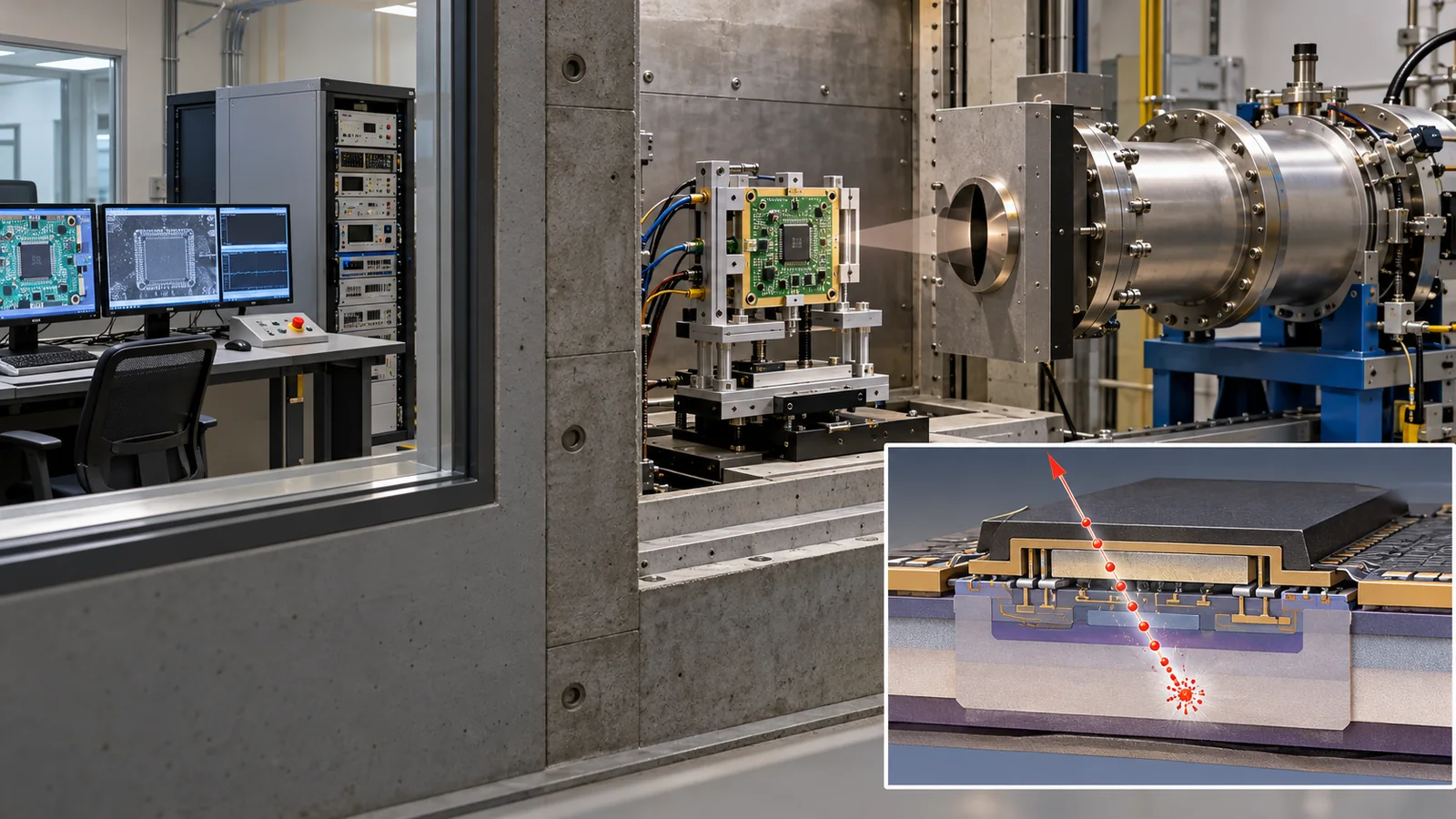
- The short version / what to know first / where this sits in the series
- Where space radiation comes from
- What happens to electronic parts: effects that accumulate and single-event effects
- TID: charge builds up in oxides
- SEE: malfunctions and damage from a single particle
- How parts are tested: imitating space on the ground
- Building it into design: radiation hardness assurance (RHA) and margin
- Where things stand now (checked 17 October 2026)
- How to read the yardsticks and standards
- Glossary / References / Claim-to-source audit
Sourced = stated in published material (link given)
Our calculation = a value this article calculated or organized, with the assumptions stated
Not yet confirmed = a draft, a revision in progress or a plan that is not settled
Structural readings and materials-design interpretations are marked separately as Commentary. Inference is shown in bold. Every analogy comes with a "limit of the analogy".
Radiation levels and test conditions are given only as values found in the source standard or paper. Even where a standard is a common yardstick, it does not guarantee that an individual part can be used in space. We read the openly published text of the ECSS standards; for ESCC, MIL-STD, JEDEC, ISO and AIAA documents we checked only titles, numbers and scope, not the texts. Numerical examples (doses and margins) are illustrative and are not values for any particular part or satellite. This field changes fast, so the status of standards carries a checking date (17 October 2026).
1. The short version / what to know first / where this sits in the series
- There are two kinds of radiation effect: effects that accumulate over a long time (TID, total ionizing dose, and displacement damage) and effects caused by a single particle (SEE, single-event effects, from bit flips to burnout)Sourced[Ref. 2, 4].
- The amount differs greatly by orbit: ECSS names three sources, the radiation belts, solar energetic particles and galactic cosmic rays, and says that in some orbits the dose a part receives can reach hundreds of krad (1 rad = 1 cGy)Sourced[Ref. 1].
- Tests and design confirm a "margin": ECSS-Q-ST-60-15 sets requirements for radiation hardness assurance (RHA) and asks for a minimum margin (MRDM) of 1.2 for TID and displacement damage. For SEE, the device's LET threshold decides the range of assessmentSourced[Ref. 4].
You need no prior knowledge. "Radiation is particles or light that give energy to matter they hit" and "electronic parts are made of semiconductors and insulating films" are enough. The overall picture of the space environment (the five enemies) is in this series' explainer on the space environment and materials, radiation degradation of solar cells in the explainer on solar cells for space, and effects on batteries in the explainer on batteries for space. The units of radiation dose are the rad and the gray (Gy); read 1 Gy = 100 rad (1 krad = 10 Gy).
Of the "five enemies" of the space environment, this article covers 2. radiation from the side of electronic parts. After it, reading our explainer on space-grade semiconductors and COTS (the thinking on commercial parts versus radiation-hardened ones, and new semiconductors such as SiC and GaN) and our explainer on computing in orbit makes "what to test and how to choose" easier to follow. Radiation at the Moon and in deep space also relates to our explainers on the Moon and Artemis and on nuclear power for space.
2. Where space radiation comes from
"Radiation" may bring to mind X-rays like those at the doctor's. In space the main concern is particles with high energy (electrons, protons and heavy ions). According to the ECSS standard, they come from three placesSourced[Ref. 1].
- Radiation belts (Van Allen belts): bands of electrons and ions trapped by the Earth's magnetic field, extending from about 100 km to 65,000 km altitude and consisting mainly of electrons up to a few MeV and protons up to several hundred MeV. Their strength changes with solar activity. The South Atlantic Anomaly is where the inner belt reaches down to low altitude.
- Solar energetic particles (SEP): short, explosive bursts of particles linked to solar activity, which last from a few hours to several days in Earth orbit. They consist of protons, electrons and heavy ions with energies from tens of keV to GeV. The Earth's magnetic field shields against them to some degree.
- Galactic cosmic rays (GCR): particles that arrive from outside the solar system, from every direction. The flux is small, a few per cm² per second, but includes highly energetic heavy ions that can deposit a lot of energy in a single hit. They are reduced when solar activity is high, because of the solar wind.
ECSS says such particles easily penetrate the walls of a typical spacecraft and, in some orbits, can deliver doses of hundreds of krad over a mission (1 rad = 1 cGy)Sourced[Ref. 1]. 10 krad corresponds to 100 GyOur calculation. A review by Pearton and co-workers also points out that the effects of heavy ions of galactic cosmic rays cannot be shielded (in the context of wide-bandgap semiconductors) [Ref. 7].
A vacuum means no shielding by air. On the ground, the atmosphere and the geomagnetic field stop most of the radiation. In space those are absent, so a part is hit by far more radiation than on the ground. Limit of the analogy: "rain with no umbrella" shows the lack of shielding but not that the kinds and energies of radiation differ by orbit.
3. What happens to electronic parts: effects that accumulate and single-event effects
When radiation hits a semiconductor part it gives up energy in two ways. One is ionization (knocking electrons loose to create electron-hole pairs), the other is displacement (moving atoms from their original positions and disordering the crystal). ECSS-E-ST-10-12C defines the former as "ionising dose" and the latter as "displacement damage"Sourced[Ref. 2].
Combine these two mechanisms with two time patterns, "accumulating" and "in one hit", and you get the sorting above. ECSS-Q-ST-60-15 lists the main radiation effects on electronic components that RHA handles as three: TID (total ionizing dose), displacement damage (TNID, total non-ionizing dose) and SEE (single-event effects)Sourced[Ref. 4].
In most cases it does not. TID is a phenomenon in which charge builds up in insulating films and shifts electrical characteristics; parts do not melt or get holes. Many SEEs, such as a memory bit changing once (SEU), are recoverable by reset or correction. On the other hand, some SEEs, such as SEL (latch-up) and SEB (burnout), can destroy a device, so it matters to think about "what can happen" kind by kind.
4. TID: charge builds up in oxides
TID is the phenomenon in which charge produced by ionization builds up in oxides and other insulators inside a part. The review by Schwank and co-workers (2008) says electrons and protons in space create oxide-trapped charge and interface traps, which cause large threshold-voltage shifts and increased leakage currentSourced[Ref. 3]. It also says that, in advanced commercial technologies, the total-dose hardness of a part is often set by charge buildup in parasitic field oxides or SOI buried oxides [Ref. 3].
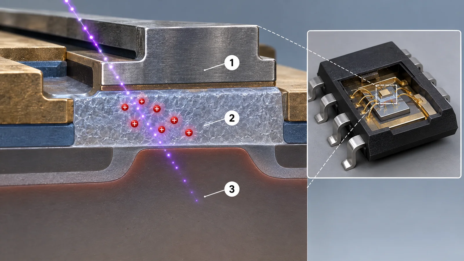
View original SVG, values and sources
Original SVG reference: Conceptual diagram (vector drawing). That charge built up in oxides and at interfaces causes threshold-voltage shifts and increased leakage follows the abstract of Schwank et al. (2008)Sourced [Ref. 3]. "Less mobile holes tend to be trapped" is a general explanation and our commentary. The curves show the shape only and are not measurements.
(1) Reading the amount: dose and dose rate
The amount of TID is expressed as the energy absorbed in the material (absorbed dose), usually in silicon-equivalent rad(Si) or Gy(Si). ECSS requires that, in TID testing of parts that contain bipolar transistors, the dose rate be below 360 rad/hSourced[Ref. 4] (360 rad/h is 3.6 Gy/h, Our calculation). The dose rate in space is very low, so raising the rate in a test could miss devices that degrade more at low dose rate (ELDRS, enhanced low dose rate sensitivity) (commentary).
ECSS-Q-ST-60-15 defines ELDRS (greater degradation of electrical parameters at lower dose rate) and rebound (in MOS structures, further degradation over several weeks after irradiation as trapped oxide charge and interface-state density change), and says that devices showing rebound must not be used unless test data justifying acceptance is providedSourced[Ref. 4]. Limit of the analogy: "a bruise that hurts more later" captures getting worse with time but not that the cause is charge in the material.
Schwank and co-workers name hafnium oxides and reoxidized nitrided oxides (RNO) as dielectrics studied as alternatives to silicon dioxide, and say that, with advanced technologies using alternate dielectrics, radiation-induced voltage shifts may be negligible [Ref. 3]. Commentary: oxide thickness, additions such as nitrogen and the density of defects all affect how readily charge is trapped, so even among "MOS" parts, differing manufacturing processes (diffusion mask, wafer fab) can mean differing tolerance. This is probably why ECSS-Q-ST-60-15 requires that tested parts be made with the same process, the same diffusion mask and the same wafer fab as the flight parts [Ref. 4].
(2) Displacement damage (DD / TNID)
Displacement damage is the phenomenon in which particles move atoms from their sites and change the electrical, mechanical or optical properties of the crystal; it matters for parts that turn light into electricity such as optical sensors, CCDs and solar cellsSourced[Ref. 1]. ECSS-Q-ST-60-15 sets the minimum margin for TNID at 1.2 too [Ref. 4]. The mechanism is the same as in the explanation of displacement damage in the explainer on solar cells for space.
5. SEE: malfunctions and damage from a single particle
An SEE occurs when a single particle passes through a sensitive part of a device. ECSS-E-ST-10-12C defines an SEE as an effect caused by direct ionization, or by ionization from recoiling nuclei produced in a nuclear interactionSourced[Ref. 2]. By what follows, SEEs are divided into non-destructive and destructive.
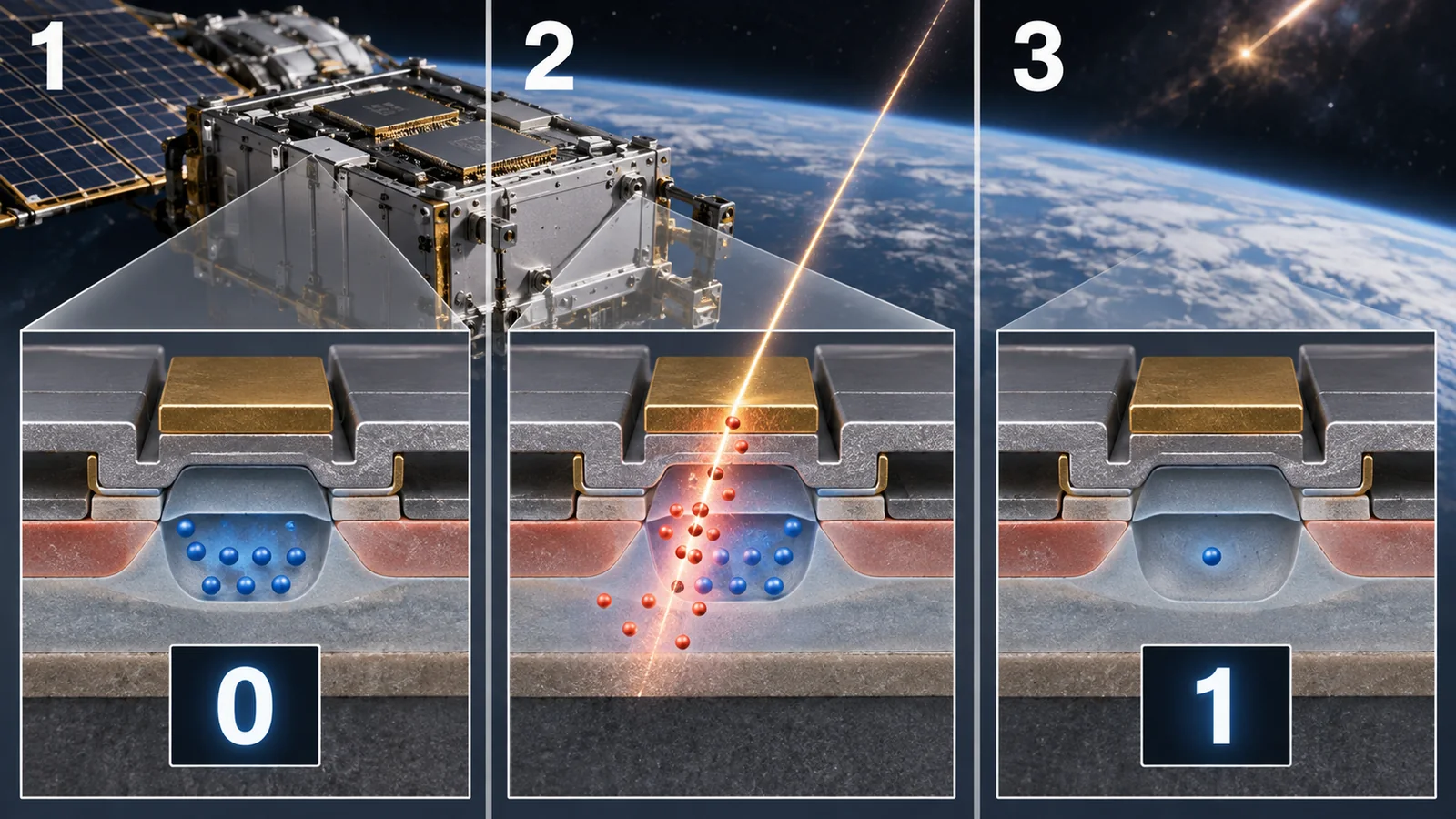
View original SVG, values and sources
Original SVG reference: Conceptual diagram (vector drawing). The definitions of SEU as "a single bit flip", critical charge as "the minimum charge that results in a SEE" and LET as "the rate of energy deposited along the path" follow ECSS-E-ST-10-12CSourced [Ref. 2]. Circuit shapes and charge sizes are schematic.
In a single-event upset (SEU), when a heavy ion passes, many electron-hole pairs are created along its track, and if the charge collected at the sensitive volume exceeds the critical charge (the minimum charge that results in an SEE), a memory bit flips. The rate at which a particle deposits energy along its path is the LET; the larger the LET, the more readily an SEE occursSourced[Ref. 2]. The review by Dodd and Massengill covers the mechanisms of non-destructive SEE in silicon MOS devices (DRAM, SRAM, combinational logic), techniques for mitigating SEU, and the impact of technology scaling on SEE susceptibility [Ref. 5].
(1) What to assess: classes by LET threshold
ECSS-Q-ST-60-15 sets the range of assessment by the device's LET threshold (the LET at which SEEs begin). For a threshold below 15 MeV·cm²/mg, both heavy ions and protons are assessed; for 15 to 60, heavy ions; and above 60, parts are commonly considered immune to SEE in the space environment and no analysis is requiredSourced[Ref. 4]. The standard also notes that CMOS at 65 nm or below with a LET threshold under 1 can be sensitive to SEE induced by protons via direct ionization [Ref. 4].
A device with a small (weak) LET threshold goes over its critical charge even with the small energy deposited by direct ionization from a light particle such as a proton, not only from heavy ones. One reason is probably that scaling makes the charge in the device smaller (the critical charge falls) (commentary; the review by Dodd and Massengill treats the effect of technology trends on SEE susceptibility [Ref. 5]). Limit of the analogy: "a small cup overflows with a little water" shows what a critical charge means but not the mechanism of ionization.
(2) Handling destructive SEE
For SEEs that can destroy a device, such as SEL, SEB and SEGR, ECSS-Q-ST-60-15 says that, for a part not immune, it must be shown that the probability of occurrence in the mission environment during the radiation design lifetime is more than 10 times lower than the part's intrinsic failure rate, or the event rate must be included in the equipment's reliability calculationSourced[Ref. 4]. ECSS defines SEL as the potentially destructive triggering of a parasitic PNPN thyristor structure, and SEB as the destructive triggering of a vertical n-channel transistor or power NPN transistor accompanied by regenerative feedback [Ref. 2].
6. How parts are tested: imitating space on the ground
To confirm on the ground what would happen in space, parts are exposed to radiation from accelerators and radiation sources. The table below sorts the test standards that ECSS-Q-ST-60-15 refers to, and the JEDEC standards.
| Effect to be confirmed | Radiation source | Test standard (number, title) | What was confirmed |
|---|---|---|---|
| TID (total ionizing dose) | Gamma rays and similar | ESCC 22900 "Total dose steady state irradiation test method", MIL-STD-883 method 1019 "Ionizing radiation (total dose) test procedure", MIL-STD-750 method 1019 "Steady-state total dose irradiation procedure" | ECSS-Q-ST-60-15C Rev. 1 makes testing by these methods one of the conditions for accepting TID data [Ref. 4]Sourced |
| Displacement damage | Neutrons, protons, electrons | ESCC 22500 "Guidelines for displacement damage irradiation testing", MIL-STD-883 method 1017 "Neutron irradiation", MIL-STD-750 method 1017 | Referred to by ECSS-Q-ST-60-15C Rev. 1 [Ref. 4]Sourced |
| SEE (heavy ions) | Accelerators such as cyclotrons (ions with atomic number Z above 2) | ESCC 25100 "Single event effect test method and guidelines". JEDEC JESD57A "Test procedure for the management of single-event effects in semiconductor devices from heavy ion irradiation" (November 2017) | ECSS requires testing to ESCC 25100 and gives JESD57 as useful information [Ref. 4]. JESD57A assumes a cyclotron or Van de Graaff accelerator, delidded devices and ions with Z above 2, and does not apply to protons, neutrons or other lighter particles [Ref. 8]Sourced |
| SEE (protons) | Proton accelerators (40 to 500 MeV) | JEDEC JESD234 "Test standard for the measurement of proton radiation single event effects in electronic devices" (October 2013) | JESD234 says that for protons of 40 to 500 MeV, indirect ionization (from secondary particles of nuclear reactions) is the dominant cause of SEE and direct ionization is minor [Ref. 9]Sourced |
| SEB and SEGR (power MOSFETs) | Heavy ions | MIL-STD-750 method 1080 "Single event burnout and single event gate rupture test" | ECSS requires this method for SEE tests of power MOSFETs [Ref. 4]Sourced |
Checked 17 October 2026. The ESCC documents themselves require a login, so their numbers and titles were checked in the list of references of ECSS-Q-ST-60-15C Rev. 1. The numbers and titles of the MIL-STD documents were also checked in the same list; their texts were not checked. JEDEC numbers, titles and scope were checked on the standard pages.
As conditions for accepting test data, ECSS-Q-ST-60-15 lists: (1) testing to the specified method; (2) tested parts made with the same process and the same diffusion mask as the flight parts (and, for TID, the same wafer fab); and (3) test conditions (bias, clock frequency, pattern, temperature and so on) worse than or equivalent to the applicationSourced[Ref. 4]. It also requires that the dose deposited during X-ray inspection of boards be recorded and counted in the TID margin; a note says another standard (ECSS-Q-ST-70-61) requires that the inspection dose be under 5% of the allowed dose of the most sensitive component [Ref. 4]. Commentary: a small difference in material or process can change tolerance, so the "origin of the data" matters.
7. Building it into design: radiation hardness assurance (RHA) and margin
Test results lead to design decisions. ECSS-Q-ST-60-15 sets requirements for radiation hardness assurance (RHA). The RHA programme is project-specific, is required for all space projects that follow ECSS-Q-ST-60, and addresses TID, displacement damage and SEE (spacecraft charging, solar cells, optical materials, adhesives, polymers and so on are outside its scope)Sourced[Ref. 4].
(1) The idea of margin (RDM)
The RDM (radiation design margin) is the dose the part withstands (TIDS) divided by the dose the part receives (TIDL). ECSS-Q-ST-60-15 sets the minimum TID margin MRDM at 1.2 (covering uncertainties of the parts themselves such as sample-to-sample variation and test uncertainty; environmental uncertainty is included in the environment specification), and obtains TIDS as the value that guarantees a survival probability of 90% at a confidence of 90% (a one-sided tolerance limit) from the spread across tested samplesSourced[Ref. 4]. The fewer the samples, the larger the allowance needed (K = 4.259 for n = 3, K = 2.065 for n = 10).
ECSS also says that, when the flight part's diffusion lot differs from the tested lot, a radiation verification test (RVT) on the flight lot is to be done for all optoelectronic parts and, for other parts, if the TID RDM is below 2Sourced[Ref. 4]. The dose a part receives (TIDL) is found taking account of shielding by the equipment walls and so on, by 3D Monte Carlo or ray-tracing analysis (with at least 2000 sectors, for example) [Ref. 4].
(2) Directions of mitigation
When margin is short, it is mitigated by adding shielding, adding redundancy, changing parts and so on. ECSS requires the mitigation to be verified by analysis or test [Ref. 4]. NASA's small-spacecraft material says that, for computers, a default approach in small-satellite avionics has traditionally been COTS components first, combined with radiation-hardened supporting electronics such as ECC, watchdog timers, scrubbing and redundancySourced[Ref. 6]. It also says that RHBD (radiation hardening by design), which changes the transistors, gates and layout so that the chip itself resists radiation, is spreading within commercial semiconductor processes [Ref. 6]. For more, see our explainers on space-grade semiconductors and COTS and on computing in orbit.
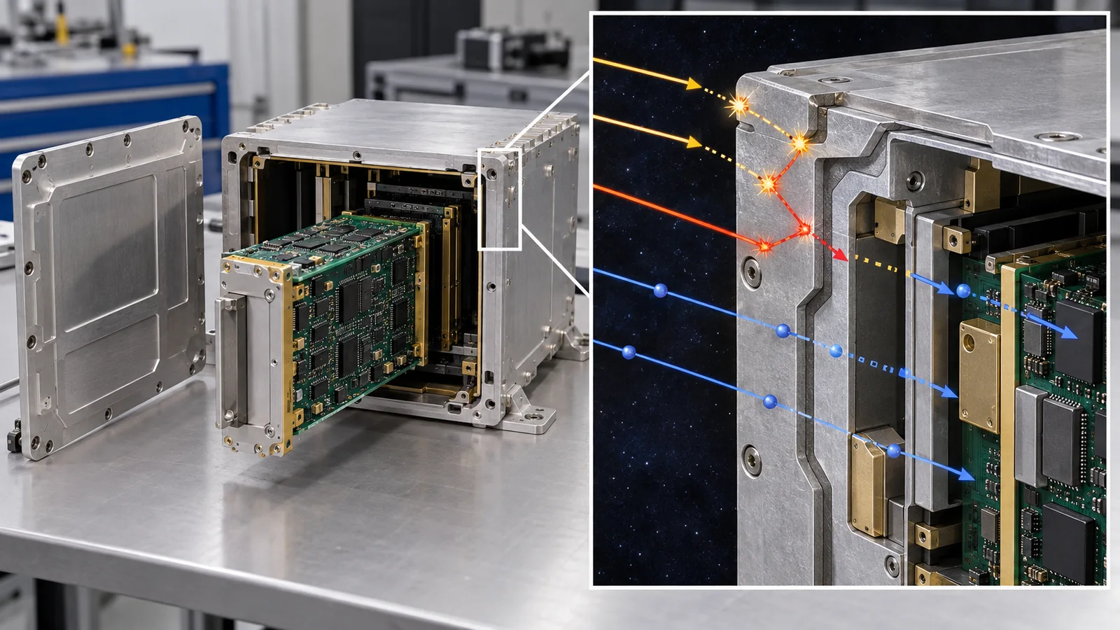
ECSS-E-ST-10-04C says energetic particles penetrate the walls of a typical spacecraft and can deliver hundreds of krad, and that energetic electrons can penetrate thin shields and build up static charge in internal insulators (cable and other insulation, circuit boards, ungrounded metal parts), with subsequent discharges producing electromagnetic interference ("internal charging")Sourced[Ref. 1]. Commentary: thicker shielding lowers the dose but makes the vehicle heavier. So the required reliability overall is secured by combining the tolerance of the parts (materials and process), redundancy and correction in the circuit, and operations (reset, power cycling). In terms of materials, the choice of insulators (materials that do not easily charge up) and the materials of boards and packages bear on charging and on SEE (see our explainer on the space environment and materials).
8. Where things stand now (checked 17 October 2026)
This field changes quickly, so we set out what could be confirmed from primary sources, with a checking date.
| Item | What was confirmed | Class |
|---|---|---|
| The RHA standard | ECSS-Q-ST-60-15C Rev. 1 (20 March 2025) is the current edition. It covers TID, TNID and SEE and specifies an MRDM of 1.2, the conditions for RVT and the classes by LET threshold [Ref. 4] | Sourced |
| The space-environment standard | ECSS-E-ST-10-04C Rev. 1 (15 June 2020) specifies models and requirements for the radiation belts, solar particles and cosmic rays. The standard model for the radiation belts is AE-8 and AP-8 [Ref. 1] | Sourced |
| Trends in commercial parts and small satellites | NASA material (2026): in small-satellite computers, combining commercial parts with radiation-hardened supporting parts and countermeasures has been the traditional approach; RHBD is spreading in commercial processes [Ref. 6] | Sourced |
| Test standards | JESD57A (November 2017) and JESD234 (October 2013) are published. ESCC 22900, 25100 and 22500 are referred to by ECSS [Ref. 4, 8, 9] | Sourced |
| Judging whether an individual part can be used in space | The standards give a common procedure; the pass or fail of each part depends on the mission's radiation specification and on test data. A guarantee for any individual part could not be confirmed in this article | Commentary |
Checked 17 October 2026. Standards continue to be revised. Check on ECSS's official pages whether the editions listed here are the latest.
Space radiation comes from three sources, the radiation belts, solar particles and cosmic rays, and causes "accumulating effects (TID, displacement)" and "single-event effects (SEE)" in electronic parts. The standard (ECSS) sets out a flow of defining the environment, comparing what each part receives with what it withstands, and judging by margin (RDM); test standards (ESCC, MIL-STD, JEDEC) give common yardsticks for measuring what a part withstands. Following a standard is not a guarantee that an individual part can be used in space; it has to be confirmed with each mission's specification and data.
9. How to read the yardsticks and standards
The radiation tolerance of an electronic part cannot be captured by one number. "How many krad of TID it withstands (TIDS)" changes with the dose rate, temperature and bias of the test. "Whether it is strong against SEE" is read through the LET threshold and the cross-section (how readily SEE occurs per amount of particles). And "whether it can be used in space" is decided by comparison with the mission's environment (orbit, duration, shielding). The table sets out what each yardstick measures and does not measure, as far as could be confirmed.
| Item assessed | Representative test or method (name, source) | Standards and guidance (ECSS, ESCC, JEDEC and others) | Cautions in reading |
|---|---|---|---|
| Definition of the environment | Calculate the amounts of radiation-belt, solar-particle and cosmic-ray radiation from orbit, duration and solar activity. Radiation belts by AE-8 / AP-8 (long-term averages) [Ref. 1]Sourced | ECSS-E-ST-10-04C Rev. 1 "Space environment" (15 June 2020). ECSS-E-ST-10-12C "Methods for the calculation of radiation received and its effects, and a policy for design margins" (15 November 2008, with a corrigendum of 22 February 2017) [Ref. 1, 2]Sourced | Models are statistical and carry uncertainty. AE-8 / AP-8 suit cumulative effects on missions longer than six months (an ECSS note) |
| Tolerance to TID (TIDS) | Steady-state irradiation tests with gamma rays and the like. For parts with bipolar transistors, a dose rate below 360 rad/h [Ref. 4]Sourced | ESCC 22900, MIL-STD-883 method 1019, MIL-STD-750 method 1019. ECSS-Q-ST-60-15C Rev. 1 (20 March 2025): MRDM of 1.2; a one-sided tolerance limit (90% survival probability, 90% confidence) [Ref. 4]Sourced | Tested parts must match flight parts in process and bias. A device showing rebound is not to be used without justification |
| Displacement damage (TNID) | Irradiation tests with neutrons, protons and electrons [Ref. 4]Sourced | ESCC 22500, MIL-STD-883 method 1017. ECSS-Q-ST-60-15: MRDM of 1.2 [Ref. 4]Sourced | Important for optical sensors, CCDs and solar cells. Sensitivity differs by device type |
| SEE (heavy ions) | Ion irradiation at an accelerator. Measure the LET threshold and cross-section [Ref. 2, 4]Sourced | ESCC 25100, JEDEC JESD57A (November 2017). Classes by LET threshold in ECSS-Q-ST-60-15 (under 15 / 15 to 60 / over 60) [Ref. 4, 8]Sourced | The basis is silicon; for GaAs, SiC, GaN and others the values are recalculated. Test conditions such as clock frequency and pattern must be worse than the application |
| SEE (protons) | Proton irradiation at 40 to 500 MeV [Ref. 9]Sourced | JEDEC JESD234 (October 2013). Proton SEE analysis is needed for a LET threshold under 15 (ECSS) [Ref. 4, 9]Sourced | For proton SEE, indirect ionization dominates (40 to 500 MeV). For CMOS at 65 nm or below, take care about direct ionization too |
| SEB and SEGR (power devices) | Tests with heavy ions [Ref. 4]Sourced | MIL-STD-750 method 1080 [Ref. 4]Sourced | The probability of destructive SEE must be under one tenth of the part's own failure rate (ECSS) |
| Lot confirmation (RVT) | Irradiation tests of samples drawn from the flight lot [Ref. 4]Sourced | ECSS-Q-ST-60-15C Rev. 1: required if the lot differs and the TID RDM is under 2; all lots for optoelectronic parts [Ref. 4]Sourced | Matters for commercial parts and devices whose lots vary greatly |
| Record in space | Records of in-orbit anomalies and malfunctions | Could not be confirmed (no general standard was found) | Ground test results and results in a real orbit may not agree, because the environments differ |
The arrangement of the table is Our calculation (organization). Numbers, titles, editions and scope were checked on the openly published ECSS text and on JEDEC standard pages (checked 17 October 2026). For ESCC and MIL-STD documents, numbers and titles were checked in ECSS's list of references; the texts were not checked. NASA's standards (NASA-STD, NASA-HDBK) on radiation could not be confirmed in this article. The ASTM International website and its standards were not consulted.
Cautions in reading (for materials engineers)
- Ground tests and on-orbit records are different: ground irradiation reproduces the varied particles and energies of space with a limited set of sources. Change the test conditions (dose rate, bias, temperature) and the result changes.
- A standard is a "procedure", not a "guarantee of passing": the ECSS standard sets the RHA procedure and a minimum margin, but whether an individual part passes depends on the mission's environment and the data. When "compliant with a standard" is claimed, check which standard and which clause.
- Check where the data came from: even for the same part number, a different manufacturing lot or process can mean different tolerance. This is why ECSS asks that tested parts match flight parts in process and that lots be confirmed.
- Requirement and advice are different: an ECSS standard becomes a requirement only when a project adopts it. ECSS says a standard may be tailored to a specific project.
10. Glossary
- TID (total ionizing dose)
- The total energy (per unit mass) a part has received through ionization. Units rad(Si), Gy(Si).
- rad / Gy / krad
- Units of absorbed dose. 1 Gy = 100 rad, 1 krad = 1000 rad = 10 Gy.
- Displacement damage (DD)
- Damage in which particles knock atoms out and disorder the crystal. Important for optical sensors and solar cells.
- TNID
- Total non-ionizing dose: a quantity expressing the size of displacement damage.
- SEE (single-event effect)
- A collective name for effects caused by a single particle passing through a device.
- SEU
- Single-event upset: one bit of a memory or similar flips.
- SET
- Single-event transient: a momentary voltage spike appears in a circuit.
- SEFI
- Single-event functional interrupt: the device temporarily stops working.
- SEL (latch-up)
- A parasitic thyristor turns on and a large current flows: a destructive behavior.
- SEB / SEGR
- Burnout / gate rupture: destructive SEEs of power devices.
- LET
- The rate at which a particle deposits energy in the material along its path. Unit MeV·cm²/mg.
- LET threshold
- The LET at which SEE begin. Larger means more tolerant.
- Cross-section
- How readily SEE occur per amount of particles (events recorded divided by fluence).
- Critical charge
- The minimum charge that results in an SEE.
- ELDRS
- Greater degradation at low dose rate. A concern for bipolar devices.
- Rebound
- In MOS structures, further degradation over several weeks after irradiation.
- RDM / MRDM
- Radiation design margin (TIDS / TIDL) / minimum margin (1.2 for TID and TNID).
- TIDS / TIDL
- The TID a part withstands / the TID a part receives.
- RHA
- Radiation hardness assurance: the plan from defining the environment through testing and checking margin to mitigation.
- RVT (RADLAT)
- Radiation verification test on the flight lot.
- Radiation belts / SAA
- Bands of particles trapped by the Earth's magnetic field (Van Allen belts) / the South Atlantic Anomaly where the inner belt reaches low altitude.
- SEP / GCR
- Solar energetic particles / galactic cosmic rays.
- RHBD
- Radiation hardening by design: raising tolerance through the construction of transistors and circuits.
- COTS
- Commercial off-the-shelf: ordinary commercial products.
11. References (primary sources)
- ECSS "ECSS-E-ST-10-04C Rev.1 – Space environment" (15 June 2020; openly published PDF) — ecss.nl/wp-content/uploads/2020/07/ECSS-E-ST-10-04C-Rev.1(15June2020).pdf
- ECSS "ECSS-E-ST-10-12C – Methods for the calculation of radiation received and its effects, and a policy for design margins" (15 November 2008, with corrigendum of 22 February 2017; openly published PDF) — ecss.nl/wp-content/uploads/2008/11/ECSS-E-ST-10-12C(15November2008)Corr.1(22February2017).pdf
- Schwank J. R. et al. "Radiation Effects in MOS Oxides", IEEE Trans. Nucl. Sci. 55, 1833–1853 (2008), DOI 10.1109/TNS.2008.2001040 — doi.org/10.1109/TNS.2008.2001040
- ECSS "ECSS-Q-ST-60-15C Rev.1 – Radiation hardness assurance – EEE components" (20 March 2025; openly published PDF) — ecss.nl/wp-content/uploads/2025/03/ECSS-Q-ST-60-15C-Rev.1(20March2025).pdf
- Dodd P. E., Massengill L. W. "Basic mechanisms and modeling of single-event upset in digital microelectronics", IEEE Trans. Nucl. Sci. 50, 583–602 (2003), DOI 10.1109/TNS.2003.813129 — doi.org/10.1109/TNS.2003.813129
- NASA "State-of-the-Art of Small Spacecraft Technology, 8.0 Small Spacecraft Avionics" (checked 17 October 2026) — nasa.gov/smallsat-institute/sst-soa/small-spacecraft-avionics/
- Pearton S. J. et al. "Review—Radiation Damage in Wide and Ultra-Wide Bandgap Semiconductors", ECS J. Solid State Sci. Technol. 10, 055008 (2021), DOI 10.1149/2162-8777/abfc23 — doi.org/10.1149/2162-8777/abfc23
- JEDEC "JESD57A: Test procedure for the management of single-event effects in semiconductor devices from heavy ion irradiation" (November 2017; scope checked on the standard page) — jedec.org/standards-documents/docs/jesd-57
- JEDEC "JESD234: Test standard for the measurement of proton radiation single event effects in electronic devices" (October 2013; scope checked on the standard page) — jedec.org/standards-documents/docs/jesd234
12. Claim-to-source audit
| Claim in the text | Basis | Class |
|---|---|---|
| Radiation belts from about 100 km to 65,000 km, electrons to a few MeV and protons to several hundred MeV, the South Atlantic Anomaly, SEP (hours to days; protons, electrons, heavy ions; tens of keV to GeV), GCR (a few per cm² per second, includes heavy ions, inverse relation to solar activity), geomagnetic shielding, hundreds of krad, penetration of spacecraft walls, internal charging, displacement damage being important for optical sensors, CCDs and solar cells, AE-8 / AP-8 as the standard radiation-belt models | ECSS-E-ST-10-04C Rev. 1 (15 June 2020) Reference 1 https://ecss.nl/wp-content/uploads/2020/07/ECSS-E-ST-10-04C-Rev.1(15June2020).pdf | Sourced |
| Definitions of absorbed dose, ionising dose, displacement damage, SEE, SEU, SET, SEFI, SEL, SEB, LET, critical charge, cross-section, COTS and RDM; 1 Gy = 100 rad | ECSS-E-ST-10-12C Reference 2 https://ecss.nl/wp-content/uploads/2008/11/ECSS-E-ST-10-12C(15November2008)Corr.1(22February2017).pdf | Sourced |
| That charge trapped in oxides and at interfaces causes threshold-voltage shifts and leakage, that in advanced commercial technology parasitic field oxides and SOI buried oxides set total-dose hardness, hafnium oxides and RNO, and SEGR from heavy ions | Abstract of Schwank et al. (2008) Reference 3 https://doi.org/10.1109/TNS.2008.2001040 | Sourced |
| The scope of RHA (TID, TNID, SEE; a project-specific programme; solar cells and materials excluded), the conditions for accepting TID test data (ESCC 22900, MIL-STD-883 method 1019, MIL-STD-750 method 1019; below 360 rad/h for bipolar; the same process), rebound and ELDRS, the one-sided tolerance limit and the K table, an MRDM of 1.2 for TID and TNID, the conditions for RVT, 3D Monte Carlo and ray tracing, the classes by LET threshold (15 and 60), the note on CMOS at 65 nm or below, the probability criterion for destructive SEE (one tenth of the part's failure rate), SEE tests (ESCC 25100, MIL-STD-750 method 1080, JESD57), the dose from X-ray inspection, mitigation, and the list of references (ESCC 22500, MIL-STD-883 method 1017 and others) | ECSS-Q-ST-60-15C Rev. 1 (20 March 2025) Reference 4 https://ecss.nl/wp-content/uploads/2025/03/ECSS-Q-ST-60-15C-Rev.1(20March2025).pdf | Sourced |
| Mechanisms of non-destructive SEE in silicon MOS devices, techniques for mitigating SEU, and the impact of scaling | Abstract of Dodd and Massengill (2003) Reference 5 https://doi.org/10.1109/TNS.2003.813129 | Sourced |
| The traditional approach of combining COTS parts with radiation-hardened supporting electronics (ECC, watchdog, scrubbing, redundancy), the spread of RHBD, and the descriptions of TID, DDD, SEE, SEU and SEL | NASA small-spacecraft technology material (avionics chapter) Reference 6 https://www.nasa.gov/smallsat-institute/sst-soa/small-spacecraft-avionics/ | Sourced |
| That the effects of galactic-cosmic-ray heavy ions cannot be shielded (in the context of wide-bandgap semiconductors) | Abstract of Pearton et al. (2021) Reference 7 https://doi.org/10.1149/2162-8777/abfc23 | Sourced |
| JESD57A's number, title and scope (ions with Z above 2, a cyclotron or Van de Graaff accelerator, delidded devices, not applicable to protons or neutrons), November 2017 | JEDEC standard page Reference 8 https://www.jedec.org/standards-documents/docs/jesd-57 | Sourced |
| JESD234's number, title and scope (40 to 500 MeV protons, indirect ionization dominant), October 2013 | JEDEC standard page Reference 9 https://www.jedec.org/standards-documents/docs/jesd234 | Sourced |
| 360 rad/h = 3.6 Gy/h, 10 krad = 100 Gy, the RDM examples (2.0 and 1.0; the doses are illustrative) | Conversions and simple calculations; assumptions stated in the text and figures Our calculation | Our calculation |
| The texts of ESCC 22900, 22500 and 25100, the texts of the MIL-STD documents, the texts of the JEDEC standards, ISO space-environment standards, NASA's standards on radiation, pass or fail of individual parts in space, and statistics of in-orbit anomalies | Could not be confirmed in the primary sources reachable for this article, and so are not stated | Commentary |
| The readings "test at low dose rate so as not to miss ELDRS", "scaling lowers the critical charge", "holes tend to be trapped", "how an oxide is made changes its tolerance" and "a mix of shielding and layers of design", and the analogies such as "rain with no umbrella" with their limits | Commentary in this article (readings based on sourced facts) | Commentary |
| That Figs. 1 to 9 are explanatory drawings and not observations of real data, and that Figs. 1 and 9 are frames for AI-generated concept images | A note by this article | Commentary |
Last updated 17 October 2026. Sources are limited to primary material (the openly published text of ECSS standards, JEDEC standard pages, NASA technical material and peer-reviewed papers). The texts of ESCC, MIL-STD and JEDEC documents were not checked; only numbers, titles and scope are given. The numerical examples (doses and margins) are illustrative calculations made for this article and are not values for any particular part or satellite. Following a standard is not a guarantee that an individual part can be used in space. The texts of ESCC, MIL-STD and JEDEC documents, pass or fail of individual parts in space, and NASA's standards on radiation could not be confirmed and are not stated here. All figures are explanatory conceptual drawings or drawings that include our own calculation; Figs. 1 and 9 are frames for AI-generated images (images not yet placed). They do not show any real facility, equipment or appearance.