TECHNOLOGY EXPLAINER
Liquid Hydrogen
— insulation and materials for moving and storing a 20 K liquid
Cooled to about 20 K (about −253 °C) at ambient pressure, hydrogen becomes a liquid whose volume is about one eight-hundredth of the gas, according to Kawasaki Heavy Industries. The price is that liquefaction takes a great deal of energy, heat leaking in makes the liquid evaporate continually (boil-off), and materials and insulation that work at cryogenic temperatures are essential. This article covers the physics and energy of liquefaction, vacuum double-wall construction and multilayer insulation, tank materials, demonstrations and safety standards, from a materials engineer's point of view.
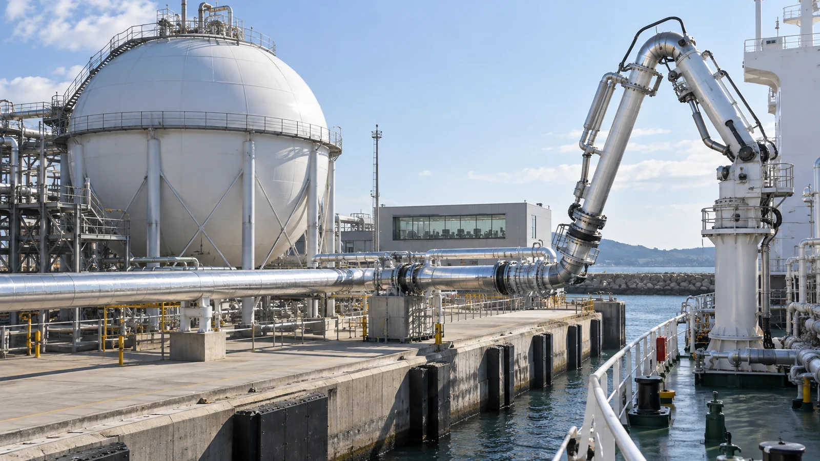
- What liquid hydrogen is, in three lines
- The physics at 20 K: boiling point, density, vapour pressure
- How much energy liquefaction takes
- Insulation and evaporation: vacuum double walls and multilayer insulation
- Tank and pipe materials: a materials engineer's view
- Demonstrations: liquid hydrogen carriers and tanks
- Safety standards and legislation
- Open issues, and what this article could not confirm
- Glossary / References / Claim-to-source audit
Sourced = stated in material published by a public body, standards body, peer-reviewed paper or company (source linked)
Our calculation = a value this article derived from explicitly stated assumptions
Not yet confirmed = plans, targets or outlooks for which no result has been confirmed
Readings of structure or materials design are marked separately as Commentary. Company and vendor figures are treated as the company's claim, and design values are distinguished from measured ones.
This article explains materials, principles, evaluation and policy. It is not advice on handling or operating liquid hydrogen or hydrogen.
1. What liquid hydrogen is, in three lines
- What it is: hydrogen cooled to a liquid. According to NIST its normal boiling point is 20.369 K (about −252.8 °C) and the density of the boiling liquid is 70.848 kg/m3 Sourced [Ref. 1]. Kawasaki Heavy Industries says liquefaction reduces the volume to about one eight-hundredth of the gas Sourced (company statement) [Ref. 7].
- What it buys: more hydrogen in the same volume than high-pressure gas (40.2 kg-H2/m3 at 70 MPa and 15 °C, NIST [Ref. 1]), and a low-pressure vessel.
- What is difficult: (1) liquefaction takes a lot of energy, (2) heat leaking in causes boil-off, (3) materials and insulation for cryogenic use are required, and (4) the components of air condense and solidify.
The value of liquid hydrogen is its density, but its cost is set mostly by the energy of liquefaction and by how good the insulation is (evaporation loss). Berstad et al. identify the assumption on the boil-off ratio of the tank as the main reason three earlier studies of liquid hydrogen reached widely different conclusions Sourced [Ref. 18]. When you read a figure, always check whether the boil-off ratio is a design value, a measurement or a target (Commentary).
How to align conditions when comparing it with other carriers is in our explainer on energy carriers; high-pressure gas is in our explainer on high-pressure hydrogen tanks, polymers such as fluoropolymers in our explainer on fluoropolymers and PFAS, and composites in our explainer on CFRP and composite materials. This article keeps to what is specific to liquid hydrogen.
2. The physics at 20 K: boiling point, density, vapour pressure
According to NIST fluid data (normal hydrogen), the normal boiling point of hydrogen is 20.369 K, the critical temperature 33.145 K, the critical pressure 1.2964 MPa and the critical density 31.262 kg/m3. The enthalpy difference between the boiling liquid and the saturated vapour (the latent heat) is about 448.7 kJ/kg, and the saturated vapour density at 20.369 K is 1.3322 kg/m3 Sourced [Ref. 1]. For parahydrogen the normal boiling point is 20.271 K and the latent heat about 446.1 kJ/kg Sourced [Ref. 2].
At 20 K the components of air such as nitrogen and oxygen (NIST gives a normal boiling point of 90.188 K for oxygen [Ref. 3]) condense and then solidify (as described in the IMO document). The IMO document lists, among the hazards of liquid hydrogen, condensation and solidification of air constituents creating an oxygen-enriched atmosphere, and notes that trace amounts of air can condense or solidify to form an unstable, explosive mixture Sourced [Ref. 11].
3. How much energy liquefaction takes
The liquefaction flow
A 2019 US DOE Program Record describes the typical flow of a large (over 3 tonnes a day) liquefier. Hydrogen at ambient temperature is precooled in a liquid nitrogen bath to about 80 K (the Claude cycle), cooled to about 40 K in a heat exchanger, and throttled to about 1.3 bar, at which it cools to 20 K and partly liquefies. A separator divides the liquid from the vapour, and the cold vapour returns through the heat exchangers to cool the incoming hydrogen. Below 3 tonnes a day a helium Brayton cycle has lower capital cost but higher energy consumption Sourced [Ref. 4].
The development of large-scale hydrogen liquefaction processes from 1898 to 2009 is reviewed by Krasae-in et al. (only the title and journal were checked [Ref. 19]).
The energy figures: read them with conditions aligned
| Figure | Value | Assumptions and source |
|---|---|---|
| Theoretical minimum work (DOE record) | 2.88 kWh/kg | Reversible (Carnot) process, inlet pressure 20 bar Sourced [Ref. 4] |
| Ideal liquefaction work (this article) | 3.36 kWh/kg | Normal hydrogen at 300 K and ambient pressure to saturated liquid at ambient pressure; ambient 300 K; ortho-para conversion energy not included Our calculation (details in our explainer on energy carriers) |
| Current industrial liquefiers (DOE record) | 10-20 kWh/kg | The smallest US plant is about 6,000 kg/day and the largest about 70,000 kg/day Sourced [Ref. 4] |
| Best plant in operation (IDEALHY) | about 11 kWh/kg | As stated in a 2013 paper Sourced [Ref. 5] |
| Design target for a large plant (IDEALHY) | under 7 kWh/kg | Design target for a 50 t/day plant Not yet confirmed [Ref. 5] |
Against hydrogen's lower heating value (33.3 kWh/kg), 2.88 is about 8.6%, 3.36 about 10.1%, 10-20 kWh/kg about 30-60%, and under 7 less than 21% Our calculation. The large gap between "theory" and "practice" is characteristic of liquefaction.
Ortho and para hydrogen: a hidden heat source
Hydrogen molecules exist as ortho-hydrogen, in which the spins of the two nuclei (protons) point the same way, and para-hydrogen, in which they point opposite ways. The DOE record explains that gaseous hydrogen at ambient temperature is about 75% ortho and 25% para while liquid hydrogen is over 99% para, that conversion occurs at 20 K but is very slow without a catalyst, and that modern liquefiers put catalysts inside the heat exchangers to speed it up Sourced [Ref. 4]. The IMO document says that the exothermic ortho-to-para conversion continues slowly after liquefaction and may affect the cooling capacity and relief valve capacity of a ship's equipment Sourced [Ref. 11]. In other words, if conversion is not completed during liquefaction, its heat causes boil-off in storage. A figure for that heat could not be confirmed in primary sources for this article.
4. Insulation and evaporation: vacuum double walls and multilayer insulation
Heat reaches the inner vessel by three routes: radiation, conduction through solids (supports and piping), and conduction and convection through residual gas (a general cryogenic-engineering framing; Commentary). What holds these down is the double-wall construction with a vacuum between the inner and outer vessels, and the insulation placed in that space.
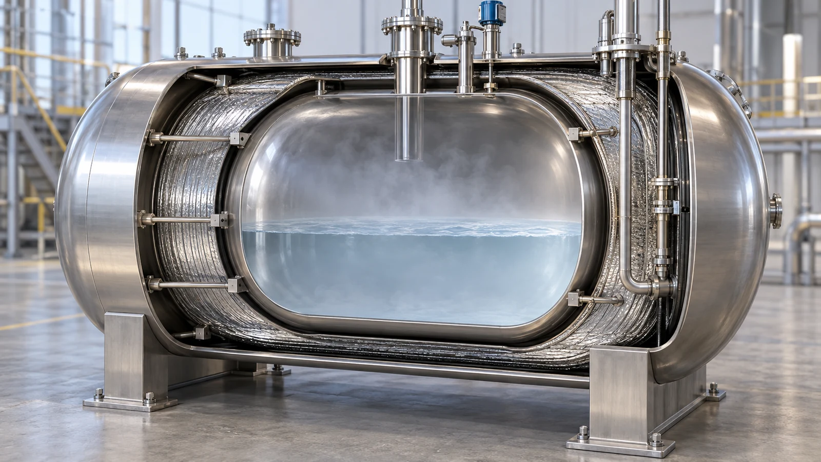
View the original SVG schematic with technical details
Kawasaki Heavy Industries' demonstration ship Suiso Frontier carries a vacuum-insulated, double-shell liquefied hydrogen storage tank of about 1,250 m3 Sourced [Ref. 7]. As an example of a large tank, a CB&I (vendor) presentation describes a tank at NASA's Kennedy Space Center with a net capacity of 1.25 million gallons (4,732 m3), in which the annular space is filled with glass bubbles (3M K1) instead of perlite, combined with a system (IRAS) that runs helium refrigerant through an internal heat exchanger to remove heat, and gives the boil-off rate as under 0.05% per day Sourced (vendor claim; presentation of February 2022) [Ref. 6]. The same presentation says glass bubbles are predicted to perform 40-100% better than perlite, and that field tests on a 190 m3 (50,000-gallon) vacuum-jacketed spherical tank at Stennis Space Center gave an average boil-off reduction of 46% over three thermal cycles in six years [Ref. 6].
Assumptions: 4,732 m3 full, liquid density 70.848 kg/m3 (NIST), latent heat 448.71 kJ/kg (NIST). Sensible heat of the vapour ignored.
The mass of liquid hydrogen is 4,732 × 70.848 = about 335 tonnes. 0.05% a day is about 168 kg a day. Multiplying by 448.71 kJ/kg gives 75 MJ a day, an average heat input of about 0.87 kW. Our calculation
For geometrically similar spheres with the same heat flux per unit area, the boil-off fraction (per unit volume) varies inversely as the cube root of volume. Going from 190 m3 to 4,732 m3 (about 25 times) would cut the boil-off rate by a factor of about 2.9 Our calculation. The bigger the tank, the better for boil-off, which is one reason for aiming at 50,000 m3 and 100,000 m3 classes (Commentary; real tanks are not geometrically similar in shape or insulation).
Multilayer insulation, and problems specific to hydrogen
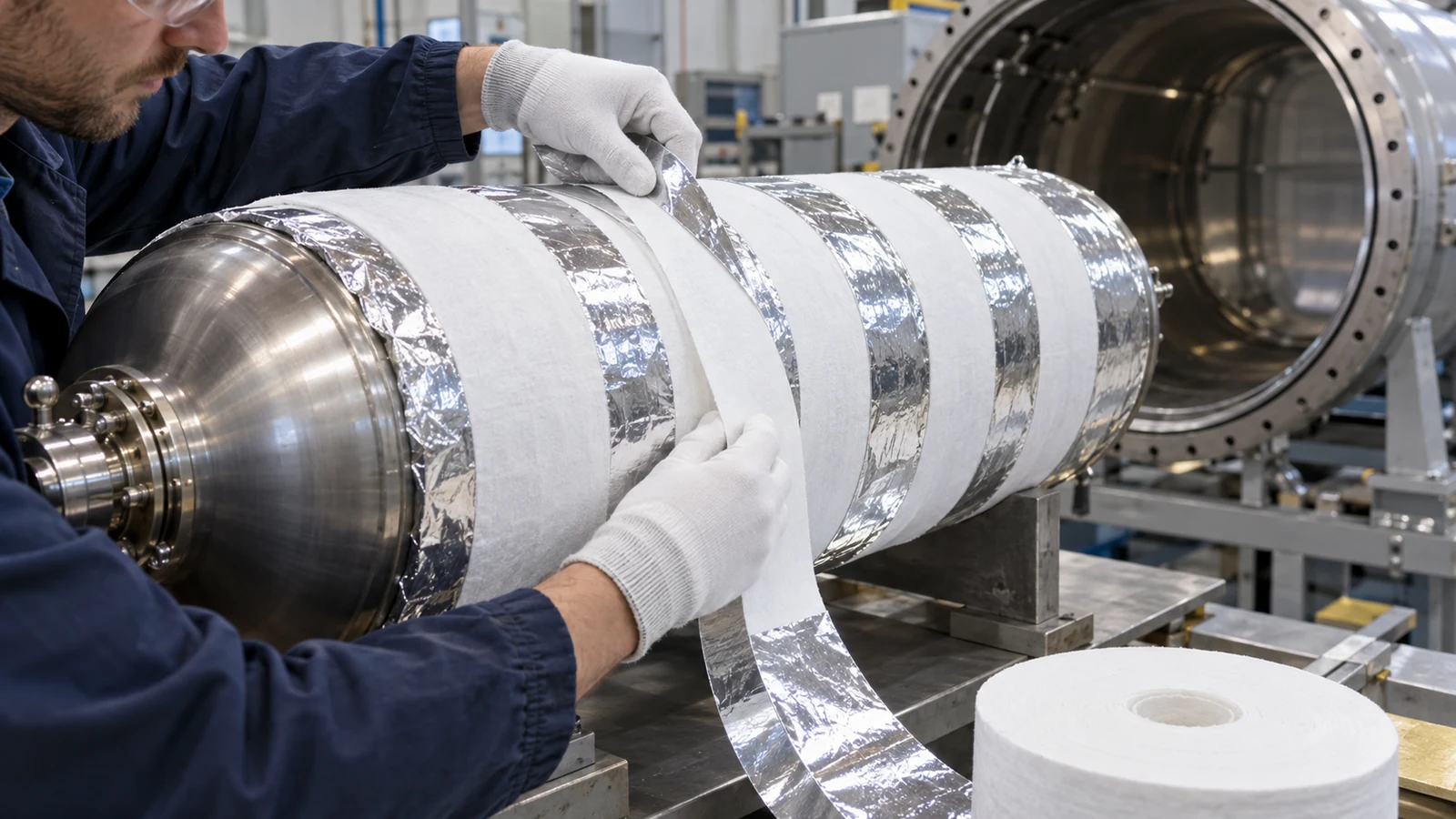
To reduce radiant heat across the vacuum space, multilayer insulation (MLI), a stack of many thin reflective layers, is widely used. A 1991 report by NASA researchers examined the thermal performance of an MLI system on a liquid hydrogen tank at varied boundary temperatures (only the title and conference were checked [Ref. 20]). Hydrogen also permeates and outgasses into vacuum spaces and degrades the vacuum, and a 2018 paper evaluated applying a hydrogen getter (adsorber) to a high-vacuum multilayer-insulated cryogenic tank (only the title and journal were checked [Ref. 21]). The IMO document likewise asks that where vacuum insulation is adopted, due consideration be given to the possibility of untimely deterioration of insulation properties at liquid hydrogen temperatures, that loss of vacuum be defined with respect to the normal range or upper limit of cold vacuum pressure, and that supports and adjacent hull structure be designed taking into account the cooling that follows a loss of vacuum Sourced [Ref. 11].
The performance of a vacuum double wall depends not only on structure but on the gases released by the materials inside (water, hydrogen and so on) and on hydrogen permeating through the walls (this can be read from the fact that the subject of the paper above [Ref. 21] is precisely the design of a hydrogen getter; Commentary). So in choosing an insulation (powder, film, glass bubbles), the evaluation items include not only thermal conductivity but the amount of outgassing, ease of evacuation, and powdering or compaction under thermal cycling (includes Inference; the CB&I presentation shows data for glass bubbles through three thermal cycles [Ref. 6]).
5. Tank and pipe materials: a materials engineer's view
The IMO's Revised Interim Recommendations for Carriage of Liquefied Hydrogen in Bulk (resolution MSC.565(108), adopted 24 May 2024) list as hazards of liquid hydrogen low ignition energy, a wide flammability range, low flame visibility, high flame velocity (possible detonation), low temperature, liquefaction and solidification of air constituents leading to an oxygen-enriched atmosphere, high permeation, low viscosity, and hydrogen embrittlement including weld metals Sourced [Ref. 11]. The main passages on materials are as follows Sourced [Ref. 11].
| Issue | What the recommendations say (summary) |
|---|---|
| Low-temperature materials | The IGC Code's material selection tables cover design temperatures of −165 °C and above. Materials for lower design temperatures are to be agreed with the Administration. Where the design temperature is below −196 °C, property testing of insulation materials is to be done with an appropriate medium over the range of temperatures expected in service. The document notes that the Code's lower test limit of −196 °C for insulation does not correspond to hydrogen's normal boiling point of −253 °C |
| Resistance to oxygen enrichment | Materials and insulation must resist the effects of high oxygen concentrations caused by condensation and enrichment. Insulation on liquid hydrogen piping is to be non-combustible with a seal in the outer covering to prevent condensation of air. Measures are to prevent exposed cold surfaces reaching −183 °C (roughly the normal boiling point of oxygen, 90.188 K = −183.0 °C, per NIST) |
| Hydrogen embrittlement | Materials must be selected to prevent failures from hydrogen embrittlement. An AIAA publication is said to introduce materials resistant to hydrogen embrittlement and to conclude that aluminium is the material least affected. National and international standards are to be followed |
| Ice and water blockage | Relief systems and vents can be blocked by ice formed from moisture in the air, causing excessive pressure, so means of prevention are to be provided |
| Vacuum insulation | Deterioration of insulation and loss of vacuum are to be considered (chapter 4) |
All Sourced (text of IMO resolution MSC.565(108) [Ref. 11]). The resolution itself says these interim recommendations are intended to be applied to a pilot ship and may need review if applied to other ships.
NEDO's programme explanation records, among research results, that data were obtained from slow strain rate tests (SSRT) on SUS316L, as a reference for evaluating material properties in low-temperature, high-pressure hydrogen, and that its themes for regulatory review include a feasibility study of stainless steel castings for liquid hydrogen equipment and establishing a reliability evaluation method for materials in cryogenic, hydrogen environments for large liquid hydrogen tanks Sourced [Ref. 10]. The pass or fail of individual materials cannot be confirmed from these documents.
In liquid hydrogen service three things are asked at once: (1) the need for materials that do not become brittle at low temperature (austenitic stainless steels and aluminium alloys are generally the candidates; Commentary), (2) hydrogen embrittlement, in which hydrogen enters the metal and degrades its mechanical properties, and (3) the soundness of welds and heat-affected zones. The IMO text says embrittlement includes weld metals [Ref. 11]. Knowledge of hydrogen embrittlement from high-pressure hydrogen at ambient temperature probably cannot be carried over unchanged to cryogenic conditions (Inference; the mechanism and extent of hydrogen embrittlement at cryogenic temperature were not confirmed in primary sources here). That NEDO lists "establishing a reliability evaluation method for materials in cryogenic, hydrogen environments" as a task indicates that evaluation methods in this area are not yet in place [Ref. 10].
The specific material of the inner vessel of the demonstration ship, numerical mechanical properties of each material at cryogenic temperature, the fracture toughness of welds in hydrogen environments, and the behaviour of seal materials and gaskets (such as fluoropolymers) at cryogenic temperature could not be checked against primary text and are not stated. NASA's hydrogen safety standard NSS 1740.16 (1997) includes a chapter on materials compatibility, but it is an old document, and the latest standard has to be consulted for design [Ref. 17].
6. Demonstrations: liquid hydrogen carriers and tanks
The carrier Suiso Frontier and the Japan-Australia demonstration
On 11 December 2019 Kawasaki Heavy Industries announced the naming and launch of the world's first liquefied hydrogen carrier, SUISO FRONTIER: length overall 116.0 m, gross tonnage about 8,000 t, tank capacity about 1,250 m3, classed by Nippon Kaiji Kyokai (ClassNK) and owned by the technology research association HySTRA. It says the ship was developed to carry liquid hydrogen at −253 °C and 1/800 of the gas volume by sea Sourced (company statement) [Ref. 7]. HySTRA (Iwatani, Kawasaki Heavy Industries, Shell Japan, J-POWER, Marubeni, ENEOS and Kawasaki Kisen Kaisha) announced a completion ceremony for the demonstration voyage on 9 April 2022. The ship left Japan in December 2021, arrived in Australia in January 2022, loaded liquefied hydrogen produced from coal in Victoria, and returned to Japan in February 2022, unloading into a landside tank Sourced [Ref. 8].
In December 2020 Kawasaki completed and delivered the world's first liquefied hydrogen receiving terminal, "Hy touch Kobe", on Kobe Airport Island. It has Japan's largest liquefied hydrogen storage tank (volume 2,500 m3) and a loading arm that transfers liquid hydrogen from a carrier to land while keeping it at −253 °C Sourced (company statement) [Ref. 9]. Kawasaki says it is developing commercial carriers able to carry 70 to 130 times the volume of the demonstration ship Not yet confirmed [Ref. 9].
Boil-off figures: do not line up numbers of different kinds
NEDO's programme explanation (26 June 2025) records the following results and targets Sourced [Ref. 10].
- In the Japan-Australia voyage test with a full load of liquid hydrogen, a boil-off rate (BOR) of 0.3%/day was obtained, with high reproducibility against values from earlier tests.
- For a commercial 50,000 m3-class storage vessel, an insulation structure achieving a BOR of 0.26%/day was established (at trial-design stage; the detailed design of a bench-scale tank at about one tenth scale, for building the 50,000 m3 tank, was completed).
- The target of the development of marine liquefied hydrogen tanks (50,000 m3 class) is an insulation performance of BOR 0.35%/day or less, for which "prospects have been established" (a non-spherical shape was selected as the optimum structure) Not yet confirmed (verification with a test tank is in progress).
Assumptions: liquid density 70.848 kg/m3, latent heat 448.71 kJ/kg (NIST). Constant boil-off rate. Sensible heat of vapour and the handling of boil-off gas (reliquefaction, use as fuel, venting) not included.
- For the demonstration ship (1,250 m3) full at 0.3%/day: 88.6 t × 0.3% = about 266 kg a day, about 1.4 kW as heat input.
- Over a 20-day voyage at a constant rate, the fraction remaining is 0.99720 = about 94.2%, so the loss to evaporation is about 5.8%.
- For a 50,000 m3-class marine tank at 0.35%/day: 3,542 t × 0.35% = about 12.4 t a day, about 64 kW as heat.
Our calculation How the boil-off gas is handled (as fuel for an engine or boiler, reliquefied, or vented) is a design question and changes the evaluation of the loss a great deal (Commentary).
7. Safety standards and legislation
The following sets out the existence and scope of standards, statutes and public documents. The texts of standards are paid-for, so this article keeps to titles and scope statements.
| Standard or document | Title and scope (per the official page) | Status |
|---|---|---|
| ISO 13985:2006 | Liquid hydrogen — Land vehicle fuel tanks. Construction requirements and test methods for refillable liquid hydrogen fuel tanks permanently attached to land vehicles | Published (to be revised) [Ref. 12] |
| ISO 13984:2026 | Liquid hydrogen — Land vehicle fuelling protocol. Fuelling protocols for liquid hydrogen (replaces the 1999 edition, "fuelling system interface") | Published March 2026 [Ref. 13] |
| ISO 21009-1:2022 | Cryogenic vessels — Static vacuum-insulated vessels — Part 1: Design, fabrication, inspection and tests. Static vacuum-insulated cryogenic vessels with a maximum allowable pressure above 0.5 bar. Not applicable to vessels for toxic fluids | Published (a third edition is at final draft stage) [Ref. 14] |
| ISO 20421-1:2019 | Cryogenic vessels — Large transportable vacuum-insulated vessels — Part 1: Design, fabrication, inspection and testing. Large transportable vacuum-insulated cryogenic vessels of more than 450 l (the 2006 edition is withdrawn and the 2019 edition is current) | Published [Ref. 22] |
| ISO/TS 15916:2026 | Hydrogen technologies — Basic considerations for the safety of hydrogen systems. Replaces ISO/TR 15916:2015 (withdrawn January 2026) | Published [Ref. 15] |
| IMO resolution MSC.565(108) | Revised interim recommendations for carriage of liquefied hydrogen in bulk (adopted 24 May 2024). Revokes resolution MSC.420(97). Intended for application to a pilot ship | Adopted (interim) [Ref. 11] |
| Japan: General High Pressure Gas Safety Regulations, Article 7-3 | Within the technical standards for compressed hydrogen stations there are provisions for liquid hydrogen storage tanks (a liquid hydrogen tank installed in a room below ground level is to have waterproofing and a double-shell vacuum-insulated structure so that the temperature of the liquid does not rise above the normal working temperature, among others) | In force (version of 1 October 2025) [Ref. 16] |
All Sourced. Titles and status are as shown on the ISO official pages, opened in a browser in October 2026. Check the standards body for the latest edition and revision status.
8. Open issues, and what this article could not confirm
- Heat of ortho-para conversion: a figure for its contribution to boil-off in storage could not be confirmed in primary sources.
- Boil-off numbers: vendor design values, NEDO's insulation structure, measurements on a real ship and targets are mixed. Test conditions (filling, duration, weather) could not be confirmed from the announcements.
- Tank materials: the specific material of the demonstration ship and large tanks, and the extent of hydrogen embrittlement at cryogenic temperature, were not checked.
- Commercial carriers: commercial vessels 70 to 130 times the size of the demonstration ship are plans under development; construction and operating records were not checked.
- Quantifying MLI: the number of layers, apparent thermal conductivity and degradation in a hydrogen environment stay at the level of titles.
- Domestic legislation: the specific technical standards for liquid hydrogen tanks under the High Pressure Gas Safety Act (storage facilities and so on) were checked only in part.
- Cost: costs of the liquid hydrogen supply chain change greatly with assumptions and are not given here (see our explainer on energy carriers).
9. Glossary
- Liquid hydrogen (LH2)
- Hydrogen cooled to about 20 K to make a liquid.
- Boil-off / BOR
- The evaporation of part of a liquid caused by heat leaking in, and its rate (for example % per day).
- Ortho- / para-hydrogen
- Isomers of the hydrogen molecule distinguished by the direction of the nuclear spins. Hydrogen at ambient temperature is about 75% ortho; liquid hydrogen is over 99% para.
- Claude cycle
- A liquefaction method using expanders and heat exchangers. Used for hydrogen liquefaction above 3 t/day (DOE record).
- Multilayer insulation (MLI)
- Insulation that stacks many thin reflective layers in a vacuum to reduce radiant heat.
- Vacuum-insulated double shell
- A construction with a vacuum between inner and outer vessels to limit heat ingress.
- Hydrogen embrittlement
- Loss of ductility, toughness or fatigue strength of a metal when hydrogen enters it.
- SSRT
- Slow strain rate test: a test of a material's susceptibility in a hydrogen environment.
- IGC Code
- The international code for ships carrying liquefied gases in bulk. Liquid hydrogen is covered by a separate interim recommendation.
- HySTRA
- CO2-free Hydrogen Energy Supply-chain Technology Research Association, the owner of the demonstration ship.
- GCU
- Gas combustion unit: a safety device that disposes of excess boil-off gas (a term in NEDO's material).
10. References
- NIST NIST Chemistry WebBook, Thermophysical Properties of Fluid Systems: Hydrogen (normal hydrogen; saturation and isothermal properties) — webbook.nist.gov
- NIST NIST Chemistry WebBook, Thermophysical Properties of Fluid Systems: Parahydrogen — webbook.nist.gov
- NIST NIST Chemistry WebBook, Thermophysical Properties of Fluid Systems: Oxygen — webbook.nist.gov
- US DOE DOE Hydrogen and Fuel Cells Program Record 19001: Current Status of Hydrogen Liquefaction Costs (9 September 2019) — hydrogen.energy.gov
- Seemann et al. (IDEALHY) Efficient Large Scale Hydrogen Liquefaction, 4th European PEFC and H2 Forum 2013, B1304 — idealhy.eu
- CB&I (US DOE liquid hydrogen workshop material) Liquid Hydrogen Storage Technologies (23 February 2022) — energy.gov
- Kawasaki Heavy Industries World's First Liquefied Hydrogen Carrier SUISO FRONTIER Launches (11 December 2019) — global.kawasaki.com
- HySTRA (Kawasaki Heavy Industries and others) HySTRA celebrates completion of world's first liquefied hydrogen vessel voyage in Japan (9 April 2022, PDF) — global.kawasaki.com
- Kawasaki Heavy Industries Kawasaki Hydrogen Road: Paving the way for a hydrogen-based society — global.kawasaki.com
- NEDO Explanation of the programme (public version), "Technology development for building a competitive hydrogen supply chain" (interim evaluation), Document 3 (26 June 2025; in Japanese) — nedo.go.jp
- IMO Resolution MSC.565(108): Revised Interim Recommendations for Carriage of Liquefied Hydrogen in Bulk (adopted 24 May 2024) — imo.org
- ISO ISO 13985:2006 Liquid hydrogen — Land vehicle fuel tanks — iso.org
- ISO ISO 13984:2026 Liquid hydrogen — Land vehicle fuelling protocol — iso.org
- ISO ISO 21009-1:2022 Cryogenic vessels — Static vacuum-insulated vessels — Part 1: Design, fabrication, inspection and tests — iso.org
- ISO ISO/TS 15916:2026 Hydrogen technologies — Basic considerations for the safety of hydrogen systems — iso.org
- Japan (e-Gov Law Search) General High Pressure Gas Safety Regulations (Ministry of International Trade and Industry Ordinance No. 53 of 1966; in Japanese) — laws.e-gov.go.jp
- US NASA (NTRS) Safety Standard for Hydrogen and Hydrogen Systems: Guidelines for Hydrogen System Design, Materials Selection, Operations, Storage and Transportation (NSS 1740.16, 1997) — ntrs.nasa.gov
- Berstad et al. Liquid hydrogen as prospective energy carrier: A brief review and discussion of underlying assumptions applied in value chain analysis, Renew. Sustain. Energy Rev. 154, 111772 (2022) — doi.org/10.1016/j.rser.2021.111772
- Krasae-in et al. Development of large-scale hydrogen liquefaction processes from 1898 to 2009, Int. J. Hydrogen Energy 35, 4524-4533 (2010) — doi.org/10.1016/j.ijhydene.2010.02.109
- Stochl and Knoll Thermal performance of a liquid hydrogen tank multilayer insulation system at warm boundary temperatures of 630 R, 530 R, and 450 R, 27th Joint Propulsion Conference, AIAA (1991) — doi.org/10.2514/6.1991-2400
- Wang et al. Optimization and performance of highly efficient hydrogen getter applied in high vacuum multilayer insulation cryogenic tank, Vacuum 149, 87-92 (2018) — doi.org/10.1016/j.vacuum.2017.12.009
- ISO ISO 20421-1:2019 Cryogenic vessels — Large transportable vacuum-insulated vessels — Part 1: Design, fabrication, inspection and testing — iso.org
11. Claim-to-source audit
| Claim in the text | Basis | Type |
|---|---|---|
| Hydrogen (normal) normal boiling point 20.369 K, critical temperature 33.145 K, critical pressure 1.2964 MPa, critical density 31.262 kg/m3, liquid density 70.848 kg/m3, latent heat about 448.7 kJ/kg, saturation pressure (14-32 K), 40.2 kg/m3 at 70 MPa and 15 °C | NISTReference 1 https://webbook.nist.gov/cgi/fluid.cgi?ID=C1333740&Action=Page | Sourced |
| Parahydrogen normal boiling point 20.271 K and latent heat about 446.1 kJ/kg | NISTReference 2 https://webbook.nist.gov/cgi/fluid.cgi?ID=B5000001&Action=Page | Sourced |
| Normal boiling point of oxygen 90.188 K | NISTReference 3 https://webbook.nist.gov/cgi/fluid.cgi?ID=C7782447&Action=Page | Sourced |
| Typical liquefaction flow (about 80 K, about 40 K, about 1.3 bar, 20 K), Brayton cycle below 3 t/day, about 75% ortho and 25% para with over 99% para in the liquid, theoretical minimum 2.88 kWh/kg (20 bar), current industrial liquefiers 10-20 kWh/kg, sizes of the smallest and largest US plants | DOE Program Record 19001Reference 4 https://www.hydrogen.energy.gov/pdfs/19001_hydrogen_liquefaction_costs.pdf | Sourced |
| Best plant in operation about 11 kWh/kg; target under 7 kWh/kg for a large plant under design (50 t/day) | Seemann et al. (IDEALHY, 2013)Reference 5 https://www.idealhy.eu/uploads/documents/IDEALHY_EFCF-2013_Efficient_Large_Scale_Hydrogen_Liquefaction_web.pdf | Sourced / design target |
| Kennedy Space Center 4,732 m3 (1.25 million gallons) tank with boil-off under 0.05%/day, glass bubble insulation, IRAS, 46% boil-off reduction at the 190 m3 Stennis sphere, offer of 40,000 m3 and development towards 100,000 m3 | CB&I (vendor) materialReference 6 https://www.energy.gov/sites/default/files/2022-03/Liquid%20H2%20Workshop-CBandI.pdf | Sourced (company claim) |
| Naming and launch of SUISO FRONTIER (11 December 2019), specifications (length 116.0 m, about 8,000 gross tonnes, tank capacity about 1,250 m3, ClassNK, owner HySTRA), vacuum-insulated double-shell tank, 1/800 volume | Kawasaki Heavy Industries announcementReference 7 https://global.kawasaki.com/en/corp/newsroom/news/detail/?f=20191211_3487 | Sourced (company statement) |
| Japan-Australia demonstration voyage (left December 2021, reached Australia January 2022, returned and unloaded February 2022), HySTRA membership and the completion ceremony (9 April 2022) | HySTRA and Kawasaki Heavy Industries announcementReference 8 https://global.kawasaki.com/news_220409-1e.pdf | Sourced |
| Hy touch Kobe (December 2020, 2,500 m3 storage tank, loading arm); commercial carriers 70 to 130 times the volume of the demonstration ship under development | Kawasaki Heavy Industries websiteReference 9 https://global.kawasaki.com/en/hydrogen/ | Sourced / plan |
| BOR 0.3%/day (Japan-Australia voyage), insulation structure for BOR 0.26%/day at commercial 50,000 m3 class, target BOR 0.35%/day or less for a 50,000 m3 marine tank (prospects established), SSRT data for SUS316L, studies on stainless steel castings for liquid hydrogen equipment and a cryogenic hydrogen-environment materials reliability evaluation method | NEDO programme explanationReference 10 https://www.nedo.go.jp/content/800029213.pdf | Sourced / target |
| Hazards of liquid hydrogen; -165 °C, -196 °C, condensed air, hydrogen embrittlement (aluminium least affected), ice blockage, vacuum insulation deterioration and loss of vacuum, effect of ortho-para conversion, revocation of MSC.420(97), application to a pilot ship | IMO resolution MSC.565(108)Reference 11 https://wwwcdn.imo.org/localresources/en/KnowledgeCentre/IndexofIMOResolutions/MSCResolutions/MSC.565(108).pdf | Sourced |
| Title and scope of ISO 13985:2006 | ISO official pageReference 12 https://www.iso.org/standard/39892.html | Sourced |
| Title of ISO 13984:2026 and its publication (March 2026) | ISO official pageReference 13 https://www.iso.org/standard/86295.html | Sourced |
| Title and scope of ISO 21009-1:2022 | ISO official pageReference 14 https://www.iso.org/standard/76098.html | Sourced |
| Title of ISO/TS 15916:2026 and its replacement of ISO/TR 15916:2015 | ISO official pageReference 15 https://www.iso.org/standard/89423.html | Sourced |
| Provisions on liquid hydrogen tanks in Article 7-3 of the General High Pressure Gas Safety Regulations (waterproofing, double-shell vacuum-insulated structure) | e-Gov General High Pressure Gas Safety RegulationsReference 16 https://laws.e-gov.go.jp/law/341M50000400053 | Sourced |
| Title and scope of NASA hydrogen safety standard NSS 1740.16 (1997) | NASA NTRSReference 17 https://ntrs.nasa.gov/citations/19970033338 | Sourced |
| Three earlier studies of liquid hydrogen had unaligned assumptions and boundaries; the main cause is the assumed boil-off ratio | Abstract of Berstad et al. (2022)Reference 18 https://doi.org/10.1016/j.rser.2021.111772 | Sourced |
| A paper reviewing the development of hydrogen liquefaction processes from 1898 to 2009 exists (title and journal) | Krasae-in et al. (2010)Reference 19 https://doi.org/10.1016/j.ijhydene.2010.02.109 | Sourced |
| A report on the thermal performance of multilayer insulation on a liquid hydrogen tank exists (title and conference) | Stochl and Knoll (1991)Reference 20 https://doi.org/10.2514/6.1991-2400 | Sourced |
| A paper evaluating a hydrogen getter in a high-vacuum multilayer-insulated cryogenic tank exists (title and journal) | Wang et al. (2018)Reference 21 https://doi.org/10.1016/j.vacuum.2017.12.009 | Sourced |
| Title and scope of ISO 20421-1:2019 (the 2006 edition is withdrawn) | ISO official pageReference 22 https://www.iso.org/standard/68589.html | Sourced |
| 0.05%/day at 4,732 m3 = about 168 kg/day = about 0.87 kW; inverse cube-root scaling with volume (about 2.9 for 25 times); 0.3%/day for the demonstration ship = about 266 kg/day = about 1.4 kW; about 5.8% loss over 20 days; 0.35%/day at 50,000 m3 = about 12.4 t/day (about 64 kW); percentages of hydrogen lower heating value (8.6, 10.1, 30-60, under 21) | Our calculation (assumptions stated at each place); reference values from NIST [Ref. 1], DOE [Ref. 4], CB&I [Ref. 6] and NEDO [Ref. 10] | Our calculation |
| The three heat routes, the items for choosing an insulation, the reading of cryogenic material selection, and the sorting of kinds of numbers | Commentary of this article (readings based on facts confirmed in primary sources) | Commentary |
| The heat of ortho-para conversion, the material of the demonstration ship's inner vessel, the extent of cryogenic hydrogen embrittlement, quantification of MLI, and the record of commercial carriers | This article could not confirm them in the primary sources within its scope (not stated) | Commentary |
| Figs. 1 and 5 are AI-generated images, and Figs. 2, 3, 4 and 6 are explanatory drawings | Note by this article | Commentary |
Last updated 8 October 2026. Sources are limited to primary material (NIST, the US DOE, the IMO, NEDO, standards bodies, Japanese statute databases, peer-reviewed papers, and company and vendor publications). Company and vendor figures are treated as the company's claim, and design values are distinguished from measured ones. The heat of ortho-para conversion, the material of the demonstration ship's inner vessel, the extent of cryogenic hydrogen embrittlement, quantification of multilayer insulation and the record of commercial carriers could not be confirmed in published primary sources and so are not stated. Titles and status of ISO standards were checked on the official pages in a browser. Figs. 2, 3, 4 and 6 are vector drawings and Figs. 1 and 5 are AI-generated images; none of them shows a real facility or ship. This article explains materials, principles, evaluation and policy; it is not advice on handling or operating liquid hydrogen or hydrogen.