TECHNOLOGY EXPLAINER
Thermal Runaway and Battery Safety
— a cell that resists fire and a system that stops fire spreading are two different things
A lithium-ion cell packs its fuel (the anode) and its oxidizer (the cathode) into one sealed can. Thermal runaway is what happens when the two begin to react and heat generation outruns heat loss, so the process feeds itself. This article sets out, from primary sources, the order of the reactions, the measured differences between LFP and NMC cells, how a failure can spread from cell to pack, and the tests and standards used for transport, industrial, automotive and stationary applications.
- What thermal runaway is (the short version)
- The chain of reactions — what overlaps, and in what order
- Triggers — external heating, internal short, overcharge, and state of charge
- LFP and NMC — what measurements show
- Our calculation: how much gas per kWh
- From cell to pack — designs that slow propagation
- Tests and standards — transport, industrial, automotive, stationary
- Fire safety for stationary storage — NFPA 855 and UL 9540A
- Limits, and what could not be confirmed
- Glossary / Primary sources / Claim-to-source audit
Sourced = stated in published material (link given)
Our calculation = a figure this article derived, with the assumptions spelled out
Not yet confirmed = a plan, proposal or not-yet-effective item whose record or force has not been confirmed
Materials-design interpretations are marked separately as Commentary. Inference is shown in bold.
This article does not discuss the cause of any individual fire or accident, even where an official investigation report exists, because causes should not be asserted by inference. It does not rank products or companies. The temperatures and gas amounts quoted here are laboratory values for small cells; they are not a guarantee of the safety of any machine or installation, and they are not safety advice for any specific case. Decisions on installation and operation belong to the applicable laws and standards and to qualified people.
1. What thermal runaway is (the short version)
- Fuel and oxidizer in one can: a battery holds its fuel (anode) and oxidizer (cathode) in a sealed container. In normal operation they yield electrical energy; if allowed to react chemically they yield heat and gas. Doughty and Roth (Sandia National Laboratories) put it this way, and note that once a reaction starts it tends to run to completion because the two are in intimate contactSourced [Source 1]
- It feeds itself: when temperature rises, either from outside heat or from heat generated inside, exothermic reactions begin in a chain. Once heat generation exceeds heat loss the temperature climbs further. That is thermal runawaySourced [Source 4]
- Defence is layered: materials, cell, module and pack, system, and installation site each get a combination of "make it less likely" and "if it happens, keep it from spreading". The review literature does not claim that any single measure reliably stops propagationSourced [Source 5]
A cell that resists fire (for example LFP) and a system in which fire does not spread are separate properties. The first is a matter of materials and cell design, and measured differences are large. The second concerns the whole system: how cells are arranged, heat shields, venting, detection, and even how it is installed. Neither alone is enough to call something safe (Commentary).
2. The chain of reactions — what overlaps, and in what order
Thermal runaway is not one reaction. It is several exothermic reactions that stack up as temperature rises. In the introduction to their paper, Finegan et al. summarise the literature as followsSourced [Source 4].
| Approximate temperature | What happens (as reported) | Source |
|---|---|---|
| about 90–120 °C | At the anode the SEI (solid electrolyte interphase) breaks down and lithiated graphite reacts with the electrolyte, giving heat and gas | [4] (introduction); [1] (DSC: SEI breakdown from about 120 °C) |
| about 130 °C and above | Polyethylene/polypropylene separators melt, raising the risk of local short circuits. In one heating test on an NMC cell, a melting endotherm appeared at 130 °C | [4], [2] |
| about 150–250 °C | The cathode begins to decompose. In thermal-ramp tests, cathode decomposition starts somewhere between 150 and 250 °C. From NMC, oxygen is released and reacts with the electrolyte | [1], [4] |
| about 200–260 °C | Rapid reaction between lithiated graphite and electrolyte, and breakdown of the graphite itself | [4] |
| about 230 °C and above | Graphite particles can exfoliate and expose lithium to electrolyte and binder. Above 260 °C, the literature cited suggests PVdF can react with lithium and release hydrogen | [2] (discussion of reactions) |
All Sourced. Temperatures are representative values from the literature and vary with cell design, state of charge, heating rate and measurement method.
Doughty and Roth divide a thermal-ramp test (heating a cell at a programmed rate) into three stagesSourced [Source 1].
- Stage 1 (onset): self-heating begins. In practice onset is taken as a self-heating rate of about 0.2 °C/min in a thermal-ramp test (ARC is about 10 times more sensitive, at about 0.02 °C/min). Breakdown of the SEI, which exposes the anode to the electrolyte, contributes here
- Stage 2 (acceleration): continuing SEI loss and electrolyte reduction at the anode, and the start of electrolyte oxidation at the cathode surface, raise heat release. Venting and smoke may occur
- Stage 3 (runaway): high-rate cathode and anode reactions push the temperature up quickly. Runaway is loosely defined as a self-heating rate of about 10 °C/min or more; at that rate it is stated to be highly unlikely that outside intervention or cooling could quench it
The runaway temperature, T(runaway), depends strongly on cell size, design and materials, and is reported to range from 130 °C to well over 200 °CSourced [Source 1].
Each row of the table names a different material: SEI on the anode, a polymer separator, a transition-metal oxide cathode, the solvent and salt of the electrolyte, the binder. The problem is less that one of them is the villain than that everything able to react is sealed in the same can.
Golubkov et al. list sources of the gas: thermal decomposition of the SEI, reduction and combustion of carbonate solvents, hydrogen from the reaction of the binder (PVdF or CMC) with lithium, and decomposition of LiPF6 (reaction schemes that can lead to HF through PF5)Sourced [Source 2]. The same paper, however, did not measure HF; it appears only in the discussion of reactions.
To a materials engineer, the binder type, the solvent composition and additives, heat-resistant coatings on the separator, and coatings on cathode particles (Doughty and Roth describe a Sandia test in which AlF3-coated NMC raised the runaway onset by about 20 °C) each act as a separate "knob" on a different step of the chainSourced [Source 1]. How each adjustment changes the whole chain can currently only be settled by cell-level testing (Commentary). The SEI itself is covered in our explainer on SEI.
3. Triggers — external heating, internal short, overcharge, and state of charge
The conditions that can trigger runaway (abuse conditions) fall into electrical, mechanical and thermal groups. The table below follows Doughty and RothSourced [Source 1].
| Trigger | What happens (as reported) | Reading note |
|---|---|---|
| External heating | Surrounding heat or heat from a neighbouring cell brings the cell to its onset temperature | The thermal-ramp test reproduces this (about 5 °C/min is described as typical) |
| External short circuit | The most common abuse condition. Cells often tolerate it, but cells above 10 Ah, cells able to sustain very large short-circuit currents, cells with higher internal resistance and cells with low inherent thermal stability are more prone to runaway. Thermal management decides the outcome | Included in every shipping and use standard |
| Internal short circuit | Caused by a foreign object, separator failure, poor design (insufficient insulation of electrodes), manufacturing flaws such as burrs, or external pressure. Gas generation inside can also displace the electrodes into contact, and in pouch cells this can bypass separators designed to resist shorting | Described as one of the most difficult failures to defend against |
| Overcharge | Heat rises sharply once all the lithium has left the cathode. Fast charging at low temperature can plate lithium and, in some cases, grow dendrites that cause an internal short | The response to overcharge is complex and depends on current, temperature and materials |
| Mechanical damage | Penetration, crush, vibration and shock can cause an internal short. Cells of higher energy density tend to respond more energetically | Leaking flammable electrolyte can lead to secondary fires |
All Sourced (Doughty and Roth [Source 1]). A 2012 overview; it does not reflect individual cell designs since then.
State of charge sets how severe it gets
A cell at lower state of charge has less fuel for the reactions. Golubkov et al. heated commercial 18650 cells (LFP and NCA) at different states of chargeSourced [Source 3].
- Discharged cells did not go into thermal runaway when heated to about 250 °C. Both cell types had to be at least partly charged to run away
- Severity rose with state of charge. The lowest state of charge giving a pronounced runaway was 50% for the LFP cell and 25% for the NCA cell in this paper (values for these cells; they cannot be generalised)
- Onset temperature changed little with state of charge, as long as no lithium plating occurred. When overcharge plated lithium, onset fell from about 140 °C to as low as about 65 °C
Doughty and Roth also report that the response to an internal short depends on state of charge: at 100% an internal short often leads to runaway, at 80% the peak temperature can drop to about 200 °C, and at 70% it can be well tolerated, citing a study of particular cellsSourced [Source 1] (not a general rule).
Overcharge and low-temperature lithium plating are usually discussed as lifetime problems. The result above shows that plated metallic lithium can pull the onset temperature down by tens of degrees. Anode design (capacity balance against the cathode, particle surface condition, SEI quality) therefore affects both lifetime and safety. This connects to our explainers on battery evaluation and degradation, and on dendrites.
4. LFP and NMC — what measurements show
"LFP is safe" is a common phrase. How far do primary sources support it? Golubkov et al. charged three types of commercial 18650 cell fully and heated them externally, comparing the runaway temperature and the gas (sealed argon reactor; a heating rate of about 2 °C/min in the worked example)Sourced [Source 2].
| Item | LCO/NMC cell | NMC cell | LFP cell |
|---|---|---|---|
| Cathode | Blend of LiCoO2 and Li(Ni0.50Mn0.25Co0.25)O2 | Li(Ni0.45Mn0.45Co0.10)O2 | LiFePO4 |
| Capacity / upper voltage | 2.6 Ah / 4.2 V | 1.5 Ah / 4.1 V | 1.1 Ah / 3.5 V |
| Cell energy (as stated in the paper) | 9.9 Wh | 5.7 Wh | 3.5 Wh |
| Onset temperature θo | 149 ± 2 °C | 168 ± 1 °C | 195 ± 8 °C |
| Peak temperature θm | 853 ± 24 °C | 678 ± 13 °C | 404 ± 23 °C |
| Gas released | 265 ± 44 mmol | 149 ± 24 mmol | 50 ± 4 mmol |
| CO in the gas (paper's conclusion) | about 28% | about 13% | about 4% |
All Sourced (the table and conclusions of Golubkov et al. [Source 2]). Three or more tests per cell type. The cells also differ in more than the cathode (electrode thickness, electrolyte, can mass ratio, capacity), so this table does not isolate the effect of the cathode.
In a 2015 paper from the same group (18650 LFP and NCA cells, fully charged), the LFP cell reached a peak temperature of about 440 °C and released about 32 mmol of gas, while the NCA cell reached about 911 °C and about 277 mmolSourced [Source 3]. Two points stand out. First, the direction agrees: LFP is milder. Second, the onset temperature of the LFP cell differs between the two papers (about 195 °C for the 2014 cell, about 140 °C for the 2015 cell), because onset depends on the product and on how it is defined.
| Results of the 2015 paper (fully charged) | LFP cell | NCA cell |
|---|---|---|
| Nominal capacity / mass | 1.1 Ah / about 38.9 g | 3.35 Ah / about 45.4 g |
| Onset temperature θo | about 140 °C | about 139 °C |
| Peak temperature θm | about 440 °C | about 911 °C |
| Gas released | about 32 mmol | about 277 mmol |
| Gas composition (detected part) | CO2 48.3%, H2 29.4%, CO 9.1% | CO 44.8%, H2 25.7%, CO2 20.0% |
| Lowest state of charge for a pronounced runaway | 50% | 25% |
| Effect of overcharge (paper's wording) | Weak | Strong |
All Sourced (Table 10 of Golubkov et al. [Source 3]). The largest values in the paper: for the NCA cell a peak of 1075 °C and 317 mmol of gas (7.1 L at standard conditions); for the LFP cell a peak of 448 °C and 61 mmol.
Even the LFP cell reached the 400s °C, and about 30% of its gas was hydrogen, the rest being CO and CO2 (2015 paper). The authors state that the gas is flammable and, because of CO, can be toxicSourced [Sources 2, 3]. LFP does not remove the need for protection at pack level or at the installation site.
On the origin of the difference, Golubkov et al. point to the strong covalent bonds of the phosphate group, which make LFP thermally more stable, and note that layered oxides break down and release oxygen that oxidises the electrolyte, which is believed to be the main contributor to the heatSourced [Source 3]. Whether LFP releases oxygen, though, is described differently in different sources. Doughty and Roth (2012) state that LiFePO4 does not generate oxygen even when fully decomposed, and that runaway in LFP cells is dominated by anode–electrolyte reactions. The 2015 paper by Golubkov et al. says that an oxygen-releasing phase transition of heated FePO4 (charged LFP) can be detected by XRD, so LFP may also contribute oxygenSourced [Sources 1, 3]. Both sources agree on the measured "mildness"; what differs is the explanation of the mechanism. This article treats the mechanism as unresolved.
A second thing to notice is that energy content is mixed into this comparison. The LFP cell has a lower voltage and only 3.5 Wh, against 5.7 Wh and 9.9 Wh for the others. Golubkov et al. conclude that the course of thermal runaway depends strongly on the energy content of the cell, and note that the LFP cell had the lowest working voltage and energy contentSourced [Source 2]. "Milder because of the cathode" and "milder because of lower energy" cannot be separated by this table alone. Doughty and Roth list the low volumetric energy of LFP as a practical trade-off [Source 1].
5. Our calculation: how much gas per kWh
Let us convert the right-hand panel of Fig. 3 into volumesOur calculation.
- Moles per Wh: LFP cell, 50 mmol ÷ 3.5 Wh = about 14.3 mmol/Wh. NMC cell, 149 mmol ÷ 5.7 Wh = about 26.1 mmol/Wh. LCO/NMC cell, 265 mmol ÷ 9.9 Wh = about 26.8 mmol/Wh
- Volume per kWh: taking 22.4 L per mole of gas at standard conditions (0 °C, 1 atm), the LFP cell gives 14.3 mol/kWh × 22.4 L = about 320 L/kWh, and the NMC cell 26.1 × 22.4 = about 590 L/kWh
- Order of magnitude: for 1 MWh (1,000 kWh), about 320 m³ with the LFP cell's figure and about 590 m³ with the NMC cell's (standard conditions in both cases)
Assumptions and limits: this simply multiplies up a result from small 18650 cells. It is a value from an argon-filled reactor and excludes gas consumed or produced by burning in air. Golubkov et al. say it remains to be shown whether the gas and heat per unit energy are the same for large cells as for small ones [Source 3]. In a real system not every cell runs away at once, and for the same number of moles the volume is larger at higher temperature. This calculation cannot be used to design gas handling or ventilation. It is meant only to convey that as the energy of a battery grows, the total gas can become a ventilation and deflagration question for the building.
6. From cell to pack — designs that slow propagation
If one cell runs away but the failure does not spread to its neighbours, the damage is limited. The review by Bravo Diaz et al. (J. Electrochem. Soc. 2020, open access) sorts the fire-protection approaches recommended by industry into twoSourced [Source 5].
- Cells and designs that avoid it: more stable chemistries (there is said to be a consensus that LFP has higher thermal stability than LCO, LMO or NMC), separators with ceramic coatings or shutdown function, modified or non-flammable electrolytes
- Assume it will happen, and do not let it spread: detection, compartmentation, and mitigating propagation from cell to cell and module to module. This is described as common in automotive, aerospace and advanced engineering
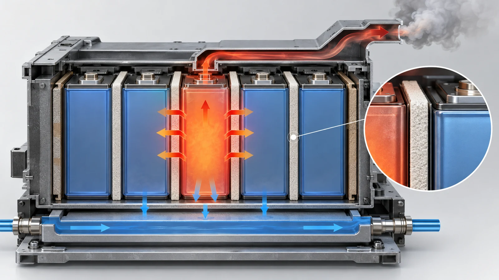
View the original SVG schematic and exact annotations
The main points on propagation inside a pack, from the same reviewSourced [Source 5]:
- Propagation is governed by heat transfer: three paths — conduction through the cell surface, conduction through the tabs, and radiation and convection from flames. Feng et al. found the heat through the cell surface to be around 10 times larger than through the tabs (cited by the review)
- Flames change the speed: Said et al. found propagation in a cell array about 9 times faster in air (with flames) than in nitrogen (without flames) (cited by the review)
- Spacing: the simplest method is to widen the gap between cells. For cylindrical cells, 2 mm is recommended by Lopez et al. (cited by the review; depends on conditions and cannot be generalised)
- Compartment materials: ceramic fibreboard (very low thermal conductivity), metal plates as heat sinks, flame-retardant plates, and phase-change materials (PCM). In the 9-cell compartment tests of Lee et al., double-layer stainless steel, intumescent material and ceramic fibreboard did not stop propagation but slowed it, with ceramic fibreboard the most effective (cited by the review)
- PCM (paraffin and the like): in one case PCM stopped propagation by absorbing latent heat, but it can be combustible and so add fire load, and it adds cost and mass
- No single method: the review concludes that no single approach has been identified to mitigate fire propagation, and that a range of safety strategies is combined to reach a sufficient level
In normal operation the pack needs heat-conducting materials (gap fillers, thermal pastes) to carry heat from the cells to the cooling plate; in a fault it needs heat-blocking materials (heat shields, barriers) so that heat is not passed on to the neighbour. Because both must share the same space, where to put what is the heart of the design. Silicone potting, foams and ceramifying coatings are covered in our explainer on automotive silicones and encapsulants, and the heat-carrying side in our explainer on thermal pastes and gap fillers. As a manufacturer's statement, Wacker says its silicone elastomers ceramify at high temperature into a hard thermally and electrically insulating layer, and that during thermal runaway temperatures briefly exceed 1,000 °C by a wide margin, in which the layer protects the carrier materialSourced (manufacturer's statement) [Source 6].
One caution: a small material fire test such as UL 94 V-0 does not guarantee a pack's thermal-runaway countermeasures (see that explainer). The properties of a material and the propagation-slowing effect of a system must be confirmed by different tests.
Bravo Diaz et al. point out that the abuse methods (triggers) built into standards and regulations do not necessarily represent real failures, and that "as of this date, no reliable method exists to create on-demand internal shorts in cells" that are representative of real failuresSourced [Source 5]. The review therefore calls for a robust propagation test in addition to the single-cell thermal runaway test. The same limit applies to the tests in Sections 7 and 8.
7. Tests and standards — transport, industrial, automotive, stationary
Many standards bear on battery safety, and they differ in which level they examine and for what purpose. A "safety test" for transport, one for building a cell into equipment, and one for installing a system are not the same thing. This article keeps to items whose number, title and scope could be confirmed on an official page or in a public document.
| Standard / rule | Main subject and purpose | What could be confirmed from official material |
|---|---|---|
| UN 38.3 (UN Manual of Tests and Criteria, Part III, sub-section 38.3) | Tests that are a precondition for transport of lithium batteries | US federal rule 49 CFR 173.185(a)(1) requires each lithium cell or battery to be of a type proven to meet the criteria in sub-section 38.3. Manufacturers keep a test record and make a test summary availableSourced [7]. There are eight tests, T.1 to T.8; T.1–T.5 are run in sequence on the same battery and T.7 on a separate one, and for small rechargeable batteries T.6 and T.8 are not required. The test names that could be confirmed are altitude simulation, thermal test, vibration, shock, external short circuit and overchargeSourced [8] |
| IEC 62619:2022 | Safety requirements for industrial secondary lithium cells and batteries (including stationary use) | Edition 2.0, published 24 May 2022. It gives telecom, UPS and electrical energy storage systems as stationary examples, and non-road motive uses such as forklift trucks. Where an IEC standard for a special application, such as the IEC 62660 series for road vehicles, conflicts with it, that standard takes precedenceSourced [9] |
| UL 9540 | Product safety standard for energy storage systems (ESS) | UL Solutions describes it as the foundational product safety standard for ESS. Its title is Standard for Energy Storage Systems and EquipmentSourced [11] |
| UL 9540A | Test method for thermal runaway and fire propagation in BESS | Title: Test Method for Evaluating Thermal Runaway Fire Propagation in Battery Energy Storage Systems. The fifth edition is dated 12 March 2025. It is a sequential test through cell, module, unit and installation, and its data support decisions on separation distances and on the fire and explosion protection needed under NFPA 855 and similar installation requirementsSourced [10, 11] |
| GB 38031-2025 (China) | Safety requirements for electric-vehicle traction batteries (mandatory standard) | Issued 28 March 2025 and effective 1 July 2026; it replaces GB 38031-2020Sourced [12]. Its content is covered below |
| NFPA 855 | Installation of stationary energy storage systems | Title: Standard for the Installation of Stationary Energy Storage Systems. NFPA's page shows the 2026 edition as current and the 2029 edition as nextSourced [13]. See Section 8 |
The text of many standards is paid, so this article relies on titles, scope, official summaries of changes and public documents. Check the standard text for the details of pass criteria.
UN 38.3 is not a "heat propagation test"
UN 38.3 checks whether a battery survives conditions that can occur in transport (low pressure, temperature change, vibration, shock, short circuit, overcharge). Among the test names this article could confirm, none evaluates propagation to neighbouring cells. Passing a transport test says nothing about how well propagation is suppressed once those cells are built into a pack (Commentary).
In a Transport Canada study, all four OEM replacement battery sets passed UN 38.3, while ten of twenty third-party replacement sets failed (the failures were seen in the vibration, external short-circuit and overcharge tests, and the short-circuit and overcharge failures tended to end in fire or explosion)Sourced [8]. It shows that the tests can detect batteries with defects, and that in practice it was hard to obtain the test summaries.
GB 38031-2025 changed how thermal propagation is required
China's mandatory standard for EV traction batteries revised its thermal-propagation requirement in the 2025 edition. According to a People's Daily article reproduced on the Chinese government portal, the earlier wording, "give a thermal-event warning signal 5 minutes before ignition or explosion", became "no fire, no explosion (a warning is still required), and smoke must not harm occupants", and a bottom-impact test and a short-circuit test after 300 fast-charge cycles were addedSourced [14].
The standard text (issued by the State Administration for Market Regulation and the Standardization Administration; the full text this article opened was posted on a municipal government page) states the followingSourced [15].
- Cell tests (seven items): over-discharge, overcharge, external short circuit, heating, temperature cycling, crush, and safety after fast-charge cycling. In every case, no fire and no explosion
- Thermal propagation (pack, system, vehicle): no fire and no explosion; a thermal-event warning signal within 5 minutes after the cell is driven into thermal runaway; and a technical statement that smoke does not create a hazard in the passenger compartment (in a vehicle-level test, no smoke entering the compartment before the warning and during 5 minutes after it)
- Trigger methods: needle penetration, external heating or internal heating; the manufacturer chooses one (other methods are also allowed). The target is a cell near the centre of the pack or surrounded by other cells
- Judging that thermal runaway has occurred: either a voltage drop of more than 25% of the initial value, or a monitoring point reaching the manufacturer's maximum operating temperature, together with a temperature rise rate of at least 1 °C/s lasting more than 3 seconds
- Observation: until every monitoring point is at or below 60 °C, and for at least 2 hours
Note that "2 hours" is the minimum observation period, not a phrase that directly requires "2 hours of safety" (our reading; some press reports describe it as a requirement, but this article follows the wording of the standard). This standard is for electric vehicles in China and does not itself govern stationary systems or the rules of other countries.
8. Fire safety for stationary storage — NFPA 855 and UL 9540A
For stationary battery energy storage systems (BESS), the roles are divided and combined: battery standards (UL 9540, IEC 62619 and others) for product safety, UL 9540A for the behaviour of thermal runaway and fire propagation, and installation codes and fire regulations such as NFPA 855 for how the system is installed. UL 9540A's scope (clause 1.2) states that its data support the manufacturer's installation instructions on separation between BESS units and the fire and explosion protection needed for an installation under NFPA 855, NFPA 70 (the US National Electrical Code), NFPA 1, the International Fire Code (IFC) and othersSourced [10].
UL 9540A: checking in sequence from cell to installation
UL Solutions explains that the fifth edition is a sequential test method (cell, module, unit, installation) in which each level has performance criteria that decide whether the next level of test is needed. It adds that BESS manufacturers designed systems to meet the unit-level criteria, so the installation-level test was not neededSourced [11].
UL Solutions, a provider of UL 9540A testing, describes what each level evaluates as followsSourced [17].
| Level | What is evaluated (UL Solutions' description) |
|---|---|
| Cell | Thermal runaway characteristics of the cell, and the composition and flammability of the gases |
| Module | Tendency of cell thermal runaway to propagate, heat and gas release rate of the module, and the potential danger of ignition or deflagration |
| Unit | Likelihood of fire spread between modules, heat and gas release rates of the unit, and the potential for deflagration or re-ignition |
| Installation | Effectiveness of the fire protection system, heat and gas release rate of the system, and the danger of deflagration or re-ignition |
UL Solutions says it offers testing to both the 5th and 6th editions (a provider's description, not the standard text).
| Item | 5th edition (dated 12 March 2025) | 6th edition (as explained by UL Solutions) |
|---|---|---|
| Test flow | Cell, module, unit, installation. If the criteria are met, the next level is sometimes not needed | Cell and module tests and criteria are kept. The protocol does not stop when the criteria are met; the installation-level large-scale fire test is run, with pass-fail criteria |
| Unit-level test | A step before the installation level | Limited to residential BESS. For non-residential systems it can also be used to evaluate an active thermal runaway propagation prevention system |
| Installation level | Effectiveness of fire protection, heat and gas release, risk of deflagration or re-ignition | The vented gas is deliberately ignited, and a developed fire is evaluated. A post-deflagration condition is assumed to assess enclosure design, separation distances and, indoors, the effectiveness of the building's fire suppression |
| Effective date | — | Expected to take effect on 1 January 2027 (UL Solutions' statement)Not yet confirmed |
The outline of the 5th edition is from UL's standards catalogue [10] and UL Solutions' explanations [11, 17]; the 6th edition is from UL Solutions' explanations [11, 17] (Sourced). The 6th-edition text is paid and was not checked.
NFPA 855 (2026 edition) and large-scale fire testing
UL Solutions explains that the 2026 edition of NFPA 855 was revised to emphasise large-scale fire testing, with a new Annex G.11 setting out expectations for tests focused on fire spreading from one BESS to anotherSourced [11]. Separately, a Tentative Interim Amendment published by NFPA (TIA No. 1852; comment closing date 17 October 2025) proposes that clause 9.2.1 refer, in addition to UL 9540A, to the large-scale fire test in Section 9.7 of CSA/ANSI C800. The stated reason is that when the second draft of the 2026 edition was developed, no consensus standard existed that defined the method of large-scale fire testingSourced [13, 16].
| Item | Stage (proposal / issued / in force) | What could be confirmed |
|---|---|---|
| NFPA 855, 2026 edition | Issued (shown as the current edition on NFPA's page) | The time at which each country, state or city incorporates it into its own rules is set separately. UL Solutions says adoption of the 2026 edition will take time. Which jurisdictions have adopted it could not be confirmed here |
| TIA No. 1852 (reference to C800) | Not yet confirmed (proposal) | Comment closing date 17 October 2025. Whether it was adopted, and its final wording, could not be confirmed here |
| UL 9540A, 5th edition | Issued (12 March 2025) | Shown as Active in UL's standards catalogue. A 6th edition is also shown as Active, but its issue date could not be confirmed here |
| UL 9540A, 6th edition | Effective date in the future (expected) | Expected to take effect on 1 January 2027 (UL Solutions). UL Solutions also says a proposal has been made to UL 9540 to require the UL 9540A edition on the marking plate and in the instructions |
| GB 38031-2025 (China) | In force | Issued 28 March 2025 and effective 1 July 2026 (national standards platform). On the date of this check (10 October 2026) it is already in force |
Proposal, issued and future are distinguished. Date checked: 10 October 2026.
As Section 4 showed, the main components of the gas from thermal runaway are hydrogen, CO, CO2 and hydrocarbons, and the gas is flammableSourced [2, 3]. The changes in the fifth edition of UL 9540A include adding hydrogen measurement at the unit-level test, making FTIR measurement optional, and adding deflagration considerations to an annexSourced [10]. UL Solutions explains that for the sixth edition the post-deflagration condition is set either by vent-area design under NFPA 68 or by explosion testing of the enclosure [11]. Design on the installation side thus looks not only at "does it burn" but at "does gas accumulate and deflagrate". From the battery side, the amount and composition of the gas (which depend on cell materials, state of charge, electrolyte and binder) become inputs to the installer's design (Commentary).
9. Limits, and what could not be confirmed
(1) The causes of individual accidents
This article does not go into the cause or responsibility for any individual accident, even where a public investigation report exists, because causes should await the conclusions of official investigations.
(2) Standard texts
The text of UN 38.3 (UNECE; automated access was refused when this article tried to retrieve it), UL 9540A, UL 9540, NFPA 855 and IEC 62619 could not be checked. The names and pass criteria of UN 38.3 tests T.6 and T.8, the test items of IEC 62619, and NFPA 855's specific separation distances and stored-energy limits are therefore not given.
(3) Vehicle regulations in Japan and Europe
Japanese JIS standards (for example the JIS C 8715 series), the UN regulation on electric-vehicle batteries (UN Regulation No. 100) and related European rules are not covered, because official material could not be confirmed.
(4) How representative the measurements are
The values in Section 4 are results of heating commercial 18650 cells in a sealed argon-filled vessel. The product, capacity, heating method, atmosphere (in air, burning changes the behaviour) and scalability to large cells all affect the result. Golubkov et al. themselves note that the behaviour of large cells and packs and the amount of HF remain to be clarified [3].
(5) Disagreement between sources
Whether LFP releases oxygen (Section 4) is described differently in different sources, and the onset temperature of the LFP cell differs between papers. This article draws no conclusion on the mechanism.
(6) Outside the scope
The safety of all-solid-state batteries is covered in our all-solid-state battery series. Battery management systems (control that prevents overcharge and over-discharge), the materials design of electrolytes and separators, and the design of stationary systems are covered in their own explainers in this series.
- Thermal runaway is a chain of exothermic reactions. The SEI, separator, cathode, anode and electrolyte, and binder overlap in order of temperatureSourced
- State of charge sets the severity. Discharged cells did not run away even at about 250 °C, and in one case lithium plating from overcharge lowered the onset from about 140 °C to as low as about 65 °CSourced
- LFP is milder in measurements (peak temperature about 404–448 °C, gas about 32–61 mmol), but it is not fireproof and it releases flammable gas. The difference in energy content is also mixed into the comparisonSourced
- Conduction through the cell surface and flames are the main propagation paths, and no single measure has been confirmed to stop itSourced
- Tests and standards sit at different levels. UN 38.3 is for transport, UL 9540A for propagation, NFPA 855 for installation. There is a move to bring in large-scale fire testingSourced (partly Not yet confirmed)
10. Glossary
- Thermal runaway
- A self-accelerating temperature rise in a cell when heat generation exceeds heat loss.
- Thermal propagation
- Spread of one cell's thermal runaway to neighbouring cells. Chinese standards call it "thermal diffusion".
- Onset temperature
- The temperature at which self-heating begins. The value depends on the measurement method and threshold.
- ARC
- Accelerating rate calorimeter, which measures self-heating under adiabatic conditions with high sensitivity.
- Thermal-ramp test
- A test that heats a cell at a constant rate until it fails.
- SOC
- State of charge. Runaway tends to be more severe at higher SOC.
- SEI
- Solid electrolyte interphase, the film on the anode surface. Its breakdown can start the heat release.
- Vent
- A safety valve or exhaust that releases gas when internal pressure rises.
- Compartmentation
- Dividing cells into compartments with barriers to slow propagation.
- BESS
- Battery energy storage system.
- AHJ
- Authority having jurisdiction, the body (such as a fire department) that approves an installation.
- Deflagration
- Combustion of flammable gas mixed with air that spreads slower than the speed of sound; pressure builds up in a confined space.
11. References (primary sources)
- Doughty D. H., Roth E. P. "A General Discussion of Li Ion Battery Safety", Electrochem. Soc. Interface 21(2), 37–44 (2012), DOI 10.1149/2.f03122if — doi.org/10.1149/2.f03122if
- Golubkov A. W. et al. "Thermal-runaway experiments on consumer Li-ion batteries with metal-oxide and olivin-type cathodes", RSC Adv. 4, 3633–3642 (2014), DOI 10.1039/C3RA45748F (open access) — doi.org/10.1039/c3ra45748f
- Golubkov A. W. et al. "Thermal runaway of commercial 18650 Li-ion batteries with LFP and NCA cathodes – impact of state of charge and overcharge", RSC Adv. 5, 57171–57186 (2015), DOI 10.1039/C5RA05897J — doi.org/10.1039/c5ra05897j
- Finegan D. P. et al. "In-operando high-speed tomography of lithium-ion batteries during thermal runaway", Nat. Commun. 6, 6924 (2015), DOI 10.1038/ncomms7924 (open access) — nature.com/articles/ncomms7924
- Bravo Diaz L. et al. "Review—Meta-Review of Fire Safety of Lithium-Ion Batteries: Industry Challenges and Research Contributions", J. Electrochem. Soc. 167, 090559 (2020), DOI 10.1149/1945-7111/aba8b9 (open access) — doi.org/10.1149/1945-7111/aba8b9
- Wacker Chemie "Improving battery safety with silicones" (manufacturer's technical article) — wacker.com
- US eCFR 49 CFR § 173.185 "Lithium cells and batteries" — ecfr.gov
- Transport Canada "Research summary – Evaluation and analysis of substandard lithium-ion batteries by UN 38.3 testing" — tc.canada.ca
- IEC "IEC 62619:2022" product page (IEC Webstore) — webstore.iec.ch/en/publication/64073
- UL Standards & Engagement "UL 9540A" (standards catalogue; 5th edition, 12 March 2025) — shopulstandards.com
- UL Solutions "Understanding UL 9540A, NFPA 855 and Large-Scale Fire Testing for Battery Energy Storage Systems" (Code Authorities) — ul.com
- National Public Service Platform for Standards Information (China) GB 38031-2025 standard information page — openstd.samr.gov.cn
- NFPA "NFPA 855 Standard Development" (current and next edition) — nfpa.org
- Chinese government portal (reprint of People's Daily) "New national standard for EV traction batteries issued, to take effect next July", 17 April 2025 (in Chinese) — gov.cn
- China national standard GB 38031—2025 full text (PDF posted on the Qinhuangdao Market Supervision Administration page; in Chinese) — scj.qhd.gov.cn
- NFPA NFPA 855-Proposed 2026 Edition, TIA Log No. 1852 — docinfofiles.nfpa.org
- UL Solutions "UL 9540A Test Method for Battery Energy Storage Systems (BESS)" (testing service page; a provider's description) — ul.com/services
12. Claim-to-source audit
| Claim in the text | Basis | Class |
|---|---|---|
| A battery holds fuel (anode) and oxidizer (cathode) in a sealed container. The practical onset definition in a thermal-ramp test (about 0.2 °C/min; ARC about 0.02 °C/min), the stage 1–3 classification, the loose definition of runaway (about 10 °C/min or more), and the runaway temperature ranging from 130 °C to well over 200 °C. The descriptions of external short, internal short, overcharge and mechanical damage (for example cells above 10 Ah). The quoted dependence of the internal-short response on SOC (runaway often at 100%, peak about 200 °C at 80%, tolerated at 70%). The roughly 20 °C rise in runaway onset for AlF3-coated NMC. The statement that LiFePO4 does not generate oxygen even when fully decomposed | Doughty and Roth (2012) Reference 1 https://doi.org/10.1149/2.f03122if | Sourced |
| The table for three 18650 cells (cathode, capacity, θo, θm, gas amount, CO share, stated cell energy). External heating of fully charged cells in argon, about 2 °C/min in the NMC example. The melting endotherm of the separator at 130 °C. The gas sources (hydrogen from binder and lithium, SEI, solvents, LiPF6) and that HF was not measured. The conclusions (the course of runaway depends strongly on energy content; the LFP cell has a low voltage and energy) | Golubkov et al. (2014) Reference 2 https://doi.org/10.1039/c3ra45748f | Sourced |
| The 18650 LFP and NCA results (θo, θm, gas amount, gas composition, lowest SOC, effect of overcharge). That discharged cells did not run away at about 250 °C, that severity rose with SOC, and that overcharge lowered onset from about 140 °C to about 65 °C. The largest values (NCA 1075 °C and 317 mmol; LFP 448 °C and 61 mmol). The statement that an oxygen-releasing phase transition of FePO4 is detected by XRD. That the gas of large cells remains unconfirmed | Golubkov et al. (2015) Reference 3 https://doi.org/10.1039/c5ra05897j | Sourced |
| The literature summary of the runaway chain (SEI breakdown at 90–120 °C, separator melting from about 130 °C, NMC decomposition with oxygen release, rapid reactions at 200–260 °C) | Introduction of Finegan et al. (2015) Reference 4 https://www.nature.com/articles/ncomms7924 | Sourced |
| The two approaches to fire protection recommended by industry, the consensus on the thermal stability of LFP, the three heat-transfer paths with “surface about 10 times the tabs” and “with flames about 9 times faster”, the 2 mm spacing, compartment materials and the results of Lee et al., the drawbacks of PCM, that no single method is identified, that the abuse methods in standards need not represent real failures, and that no reliable method exists to create on-demand internal shorts | Review by Bravo Diaz et al. (2020), including the studies it cites Reference 5 https://doi.org/10.1149/1945-7111/aba8b9 | Sourced |
| Silicone elastomers ceramify at high temperature into a hard insulating layer; temperatures in thermal runaway briefly far exceed 1,000 °C (manufacturer's statement) | Wacker technical article Reference 6 https://www.wacker.com/cms/en-us/products/insights/silicone-battery-safety.html | Sourced |
| 49 CFR 173.185(a)(1) requires a type that meets UN 38.3, record keeping and test summaries. That UN 38.3 has eight tests T.1–T.8, that T.1–T.5 run in sequence on the same battery and T.7 on another, and that T.6 and T.8 are not required for small rechargeable batteries. The test names that could be confirmed (altitude simulation, thermal, vibration, shock, external short circuit, overcharge). The Transport Canada results (4 OEM sets passed; 10 of 20 third-party sets failed; failures in vibration, external short circuit and overcharge) | US 49 CFR 173.185; Transport Canada research summary Reference 7 https://www.ecfr.gov/current/title-49/subtitle-B/chapter-I/subchapter-C/part-173/subpart-E/section-173.185 Reference 8 https://tc.canada.ca/en/dangerous-goods/publications/lithium-battery-transport-research/research-summary-evaluation-analysis-substandard-lithium-ion-batteries-383-testing | Sourced |
| The title of IEC 62619:2022, edition 2.0, published 24 May 2022, the stationary and non-road motive examples, and that special-application standards such as IEC 62660 take precedence | IEC Webstore Reference 9 https://webstore.iec.ch/en/publication/64073 | Sourced |
| The title of UL 9540A, that the 5th edition is dated 12 March 2025, the scope clauses (1.1, 1.2), and the outline of changes in the 5th edition (hydrogen measurement, FTIR optional, deflagration considerations). The title and role of UL 9540. The differences between the 5th and 6th editions, the cell→module→unit→installation flow, what each level evaluates, NFPA 855 Annex G.11, and the post-deflagration condition set by NFPA 68 vent-area design or an enclosure explosion test | UL standards catalogue; UL Solutions (a provider's explanations) Reference 10 https://www.shopulstandards.com/ProductDetail.aspx?productId=UL9540A_5_S_20250312 Reference 11 https://www.ul.com/thecodeauthority/knowledge/understanding-UL-9540A-NFPA-855 Reference 17 https://www.ul.com/services/ul-9540a-test-method | Sourced |
| The title of GB 38031-2025, issue on 28 March 2025, effect on 1 July 2026, and that it replaces GB 38031-2020 | National Public Service Platform for Standards Information (SAMR) Reference 12 https://openstd.samr.gov.cn/bzgk/gb/newGbInfo?hcno=3AB693FAFF5D9716DF61C61D6FD2187A | Sourced |
| The revision from “a warning 5 minutes before ignition or explosion” to “no fire, no explosion (a warning still required), and smoke must not harm occupants”, and the added bottom-impact test and short-circuit test after 300 fast-charge cycles | Chinese government portal (reprint of People's Daily) Reference 14 https://www.gov.cn/lianbo/bumen/202504/content_7019269.htm | Sourced |
| The seven cell tests of GB 38031-2025, the thermal-propagation requirement (no fire, no explosion; warning within 5 minutes; smoke statement), the trigger methods, the criteria for judging thermal runaway (voltage drop of more than 25% or reaching the maximum operating temperature, together with at least 1 °C/s for more than 3 s), and the observation conditions (down to 60 °C and at least 2 hours) | Full text of GB 38031-2025 Reference 15 http://scj.qhd.gov.cn/BAFa08c0dc/New/qhdscjFile/2025-06-24/2d7df285-e7fe-448e-96f2-d9729dc4e618.pdf | Sourced |
| The title of NFPA 855, that the current edition is 2026 and the next is 2029. That TIA No. 1852 proposes referring to Section 9.7 of CSA/ANSI C800, that the comment closing date was 17 October 2025, and its stated reason | NFPA standard development page; NFPA Tentative Interim Amendment Reference 13 https://www.nfpa.org/codes-and-standards/nfpa-855-standard-development/855 Reference 16 https://docinfofiles.nfpa.org/files/AboutTheCodes/855/NFPA_855_Proposed_TIA_1852.pdf | Sourced |
| That UL 9540A 6th edition is expected to take effect on 1 January 2027 (UL Solutions' statement). The adoption of TIA No. 1852 | UL Solutions states a future effective date. The TIA is a proposal; whether it was adopted could not be confirmed. Reference 11 https://www.ul.com/thecodeauthority/knowledge/understanding-UL-9540A-NFPA-855 | Not yet confirmed |
| Gas per Wh (LFP 14.3, NMC 26.1, LCO/NMC 26.8 mmol/Wh), volume per kWh (about 320 and 590 L), and about 320–590 m³ for 1 MWh | Our calculation: dividing the gas amount by the stated cell energy in Golubkov et al. (2014), taking 22.4 L per mole at standard conditions, and multiplying up the small-cell result directly. It is a value from argon, excludes burning in air, and is not usable for design | Our calculation |
| The names and pass criteria of UN 38.3 tests T.6 and T.8, the test items of IEC 62619, NFPA 855's separation distances and stored-energy limits, the standard texts, Japanese JIS and UN Regulation No. 100, the causes of individual accidents, the mechanism of oxygen release from LFP, the amount of HF, and the gas from large cells | Not given, because they could not be confirmed in the primary sources accessible to this article (the UNECE page refused automated access) | Commentary |
| The readings “thermal runaway is a property of the combination”, “LFP has less fuel rather than not burning”, “the comparison mixes in energy content”, “the same pack needs heat-conducting and heat-blocking materials”, “UN 38.3 is not a propagation test”, and “gas composition is an input to installation design”. The sorting of standards by level (Fig. 5). The arrangement of the five reaction steps (Fig. 2). The reading of “2 hours” | This article's own sorting and commentary based on the published material. Not a view stated by any company or body | Commentary |
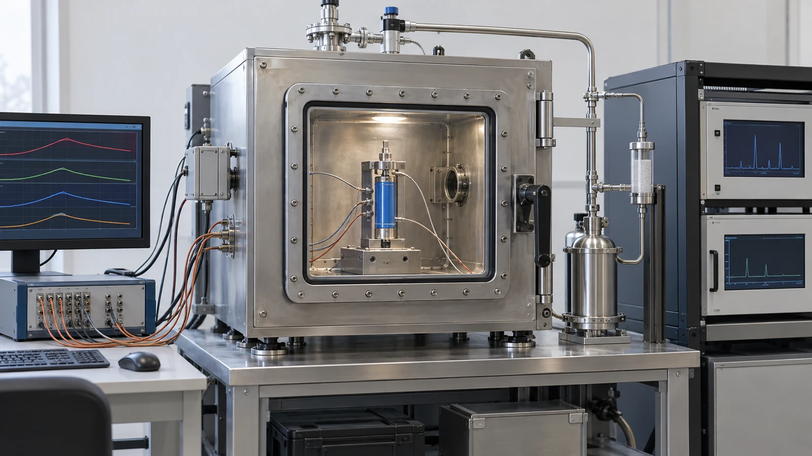
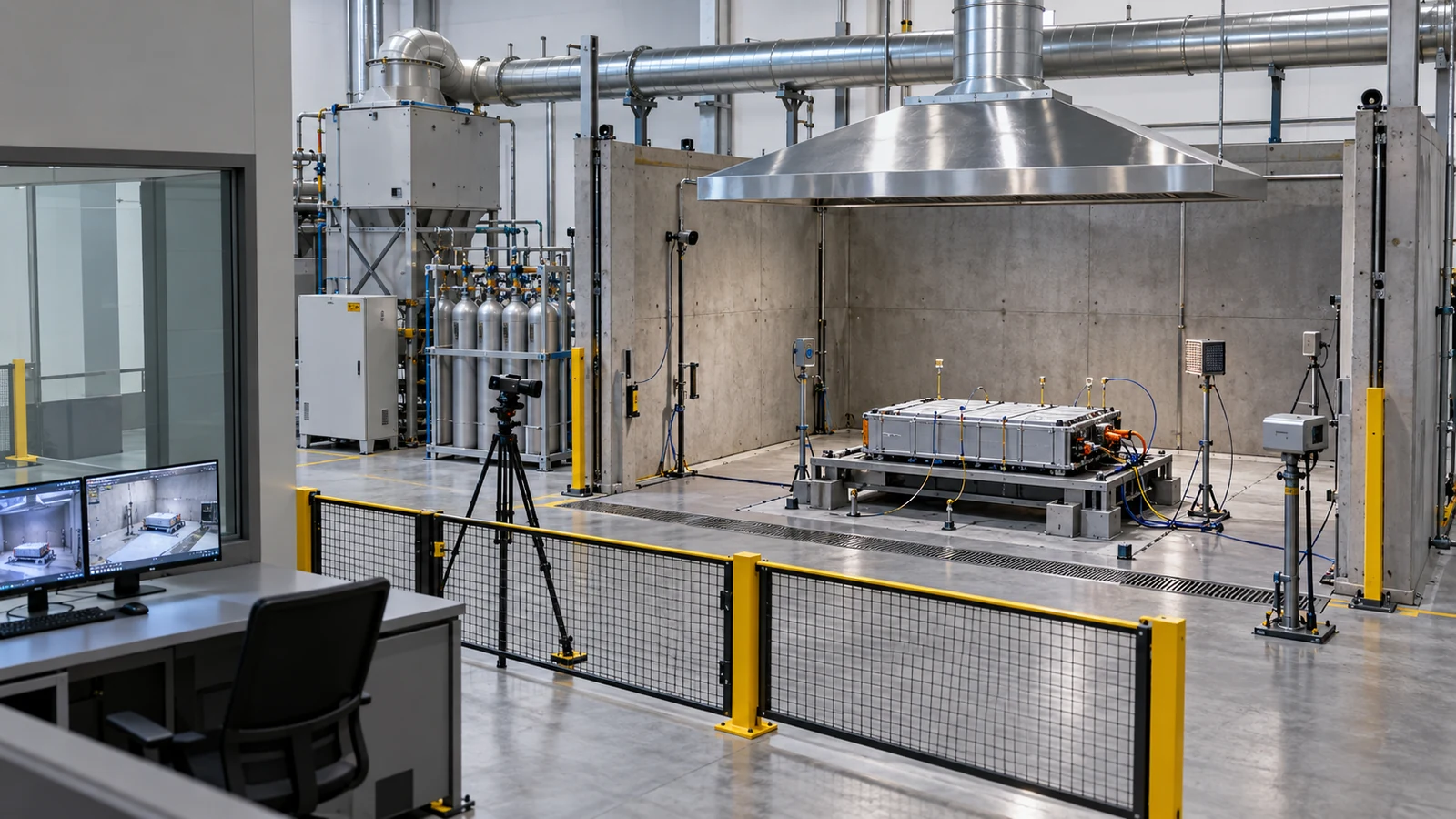
| That Figs. 2, 3, 4 and 5 are explanatory drawings, not real observations or design drawings, and that Figs. 1 and 6 are AI-generated images | Note from this article | Commentary |
Last updated 10 October 2026. Sources are limited to primary material (peer-reviewed papers, federal regulations, official pages of governments and standards bodies, standards-organisation pages, and manufacturers' technical articles). Manufacturers' statements are labelled as such, and standard texts are paid, so the texts themselves could not be checked. Because the article includes structural readings and materials-design interpretations, those are marked as Commentary and kept separate from sourced fact. The details of UN 38.3 tests T.6 and T.8, the texts of IEC 62619, UL 9540A and NFPA 855, Japanese JIS standards, the causes of individual accidents, the mechanism of oxygen release from LFP, the amount of HF, and the gas from large cells could not be confirmed and are not stated here. Standards and rules are revised; changes after the date checked (10 October 2026) are not reflected. All figures are explanatory concept graphics. Figs. 2, 3, 4 and 5 are vector drawings; Figs. 1 and 6 are AI-generated images, and none of them shows a real cross-section, micrograph or physical product.