TECHNOLOGY EXPLAINER
Inter-satellite optical communication
— How lasers link satellites, and the materials, parts and standards behind them
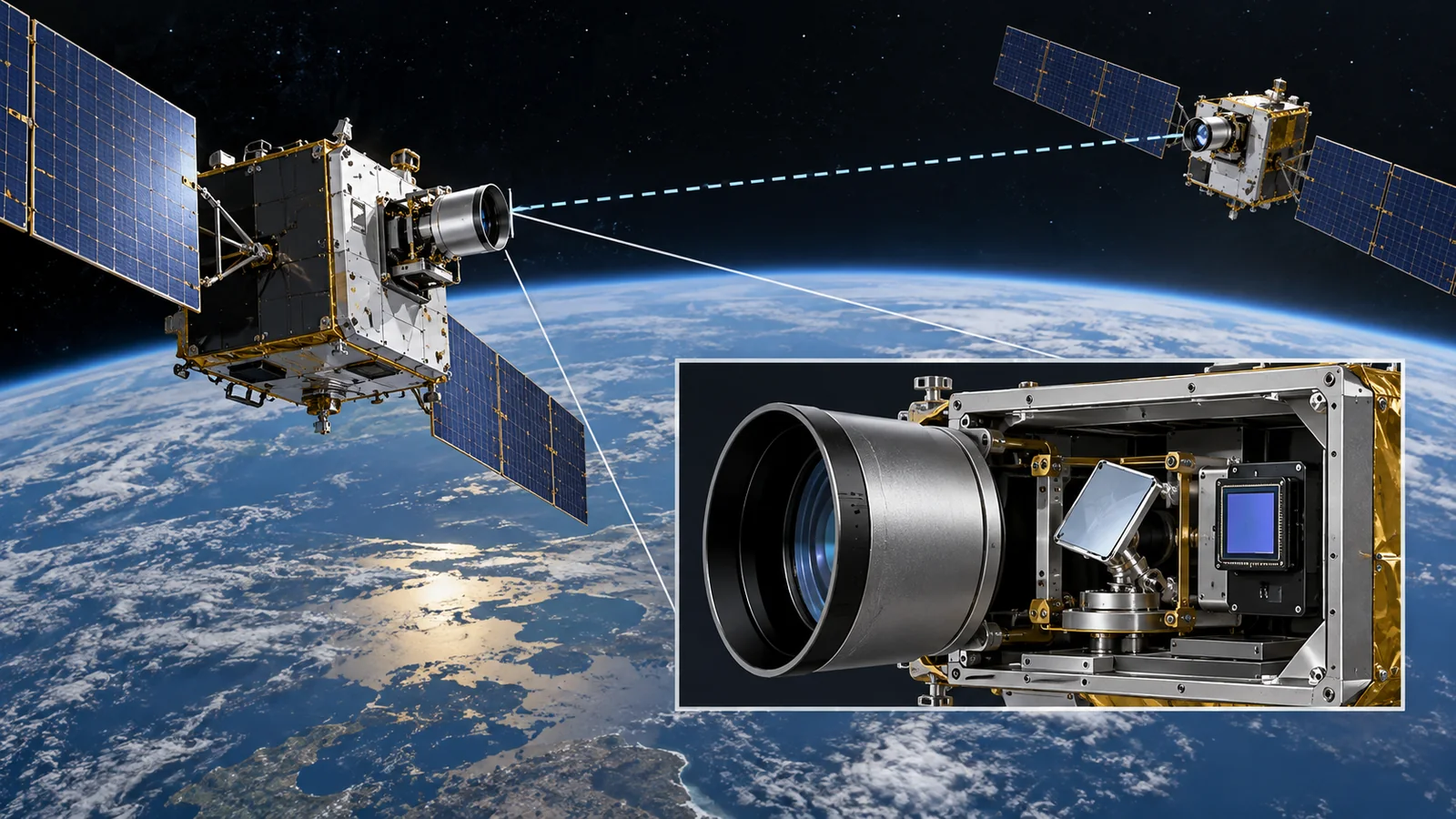
Linking satellites to each other, or to the ground, with laser light instead of radio is nearing practical use. Light can be focused much more tightly than radio, so it can carry large amounts of data with little power, but it must be aimed at the partner with great precision. This article is written so that a materials engineer with no background in spaceflight can follow it: (1) why light, with worked numbers, (2) what is inside one link, (3) pointing, acquisition and tracking, (4) real examples and standards, with CCSDS and SDA document numbers and dates, and (5) the parts and materials challenges. Each demonstration is described by what, how large and when, and company statements are kept apart from standard values.
- The short version / what to know first / place in the series
- Why light? The narrowness of the beam, with numbers
- Inside one optical link
- Aligning the light: pointing, acquisition and tracking
- How faint the received light is: photons per bit
- Demonstrations and data rates: what has been shown
- Standards: CCSDS and SDA
- Parts and materials: a materials engineer's view
- Yardsticks and standards / glossary / references / audit
Sourced = stated in a published source (link given)
Our calculation = a value this article calculated from stated assumptions
Not yet confirmed = company targets and plans, pending applications and proceedings — anything not settled
Inference is shown in bold. Every analogy comes with its limits.
The widths, photon counts and received powers in Chapters 2 and 5 are explanatory values calculated here, not design values of any real terminal. Standard values are written as they appear in SDA, CCSDS and ESCC documents, with a check date (17 October 2026). Company announcements are treated as company statements, and in-orbit demonstrations are kept apart from ground bench tests. Because this field moves fast, standard editions and statuses are as of the check date.
1. The short version, what to know first, and where this fits
- Light can be focused more tightly than radio: for the same aperture, beam spread is proportional to wavelength. In our calculation, at 1,000 km a laser beam is about 15 m wide and a Ka-band radio beam about 20 km Our calculation
- The difficulty is aiming: in ESA's EDRS the light is aligned on a 135 mm target about 45,000 km away in about 55 seconds. The SDA standard requires acquisition in 100 seconds or less Sourced [ref. 5, 1]
- Experience is accumulating and standards are taking shape: EDRS reached its 75,000th link in June 2023, and CCSDS issued Issue 2 of its optical Blue Books in March 2026. The speed figures, however, are on different footings and rank nothing Sourced [ref. 6, 3]
An "inter-satellite link" (ISL) is communication directly between satellites. Using light (laser) instead of radio makes it an optical inter-satellite link (OISL). The light is invisible near-infrared, with wavelengths such as 1,550 nm. "Bit rate" is bits sent per second (Gbps is a billion bits per second), a "beam" is the bundle of light or radio, and "aperture" is the diameter of a telescope or antenna opening. The shorter the wavelength, the more tightly the same aperture can focus the beam (limit: real beams spread more than the ideal because of lens accuracy and vibration).
The parts of optical communication (semiconductor lasers, photodetectors, optical fibre, optical modulation with thin-film lithium niobate, and coherent detection) are covered in our photonics and optical-communication series. This article focuses on what changes in space: radiation, vacuum and alignment. The previous article is on low-Earth-orbit constellations, and data processing in space is in the one on orbital computing.
2. Why light? The narrowness of the beam, with numbers
Imagine pointing a torch at a person far away. A widely spreading beam puts little light on them; a beam that can be focused stays strong at a distance. Radio and light differ in the same way: the wavelength of the light (1.55 µm) is about 1/6,000 of that of Ka-band radio (about 1 cm), so the same aperture can focus it far more tightly. A narrow beam puts more of the light into the partner's receiving aperture, so large amounts of data can be sent on little power.
The angle of beam spread can be estimated roughly as wavelength divided by aperture (in radians). For a 10 cm telescope and a 1,550 nm wavelength it is about 15.5 µrad (microradians). The SDA standard likewise sets the transmitted beam divergence at 15 µrad or more (full width at half maximum), a lower bound that can be read as protecting against pointing error from over-focusing (commentary) Sourced [ref. 1]. For a 0.5 m antenna and Ka-band (30 GHz) radio the spread is about 20 mrad Our calculation.
Reading the chart: at 1,000 km, light spreads to about 15 m and radio to about 20 km. A simple estimate of the fraction of light entering the receiving aperture (10 cm for light, 0.5 m for radio) gives about -44 dB for light and about -92 dB for radio. The difference is about 48 dB, a factor of roughly 66,000 Our calculation. The ratio is the same at any distance. So light arrives on far less power than radio, but in exchange pointing it precisely at the partner becomes essential.
The dB is a logarithmic unit for ratios. A drop of 10 dB is a factor of 10, 20 dB a factor of 100, 30 dB a factor of 1,000. -44 dB is about one 25,000th, and a 48 dB difference is a factor of about 66,000. A small-looking number stands for orders of magnitude (our calculation) Our calculation.
Cloud and turbulence matter only on links between a satellite and the ground, where light passes through the atmosphere. The SDA standard also notes that on space-to-ground links atmospheric "fadeouts" (periods when the signal falls below threshold) add to latency Sourced [ref. 1]. Links between satellites do not pass through the atmosphere, so this problem does not arise. Instead, as above, the challenge is holding an extremely narrow beam on a partner that moves fast.
3. Inside one optical link
Let us follow the parts of an optical link. On the transmit side, (1) a laser source makes the light, (2) a modulator loads data onto its intensity or phase, (3) an optical amplifier boosts it, and (4) a telescope sends it out as a narrow beam. On the receive side, (5) a telescope gathers the faint light, (6) a photodetector turns it into an electrical signal, and (7) a decoder corrects errors and recovers the data. Separately, tracking parts (a tracking sensor, a fast steering mirror and a gimbal) are essential to keep the beam on the partner.
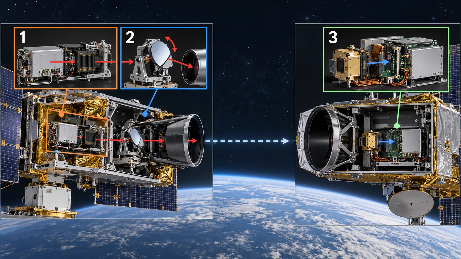
View original SVG, values and sources
Original SVG reference: Conceptual diagram (vector drawing). Left is the transmit side and right the receive side (in practice each satellite has both). Purple marks the tracking parts that keep alignment.
The SDA standard defines two channels, at 1553.33 nm (193.000 THz) and 1536.61 nm (195.100 THz), limits the modulated laser linewidth to 5 GHz or less and the centre-frequency accuracy to within ±2.5 GHz. It requires that the terminal can deliver at least 2.5 W of transmit power and be able to turn down to 40 mW or less. These requirements are set so that terminals from different makers can connect; they do not decide which terminal is better Sourced [ref. 1].
Modulation and coding are what a standard fixes. The SDA standard uses, among others, on-off keying (OOK-NRZ, which marks 0 and 1 by the presence or absence of light), defines several waveforms from 2.5 Gbaud (2.5 billion symbols a second) down to lower rates, and uses LDPC codes for error correction together with a retransmission scheme (ARQ) Sourced [ref. 1]. NASA's TBIRD, by contrast, used fibre-coupled coherent transceivers (which read the phase of the light) with ARQ to guarantee error-free communication through the fading atmosphere Sourced [ref. 8]. Coherent detection is covered in our explainer on coherent optical communication and DSP.
4. Aligning the light: pointing, acquisition and tracking
Hitting a distant partner with a thin beam is like hitting a far target with a needle tip while both are moving. Limit of the analogy: the target moves too, and although its position can be computed from a known orbit, platform shaking (jitter) adds to it. The SDA standard notes that, unlike optical fibre, free-space optical communication has no guided path, so terminals must be spatially aligned. This alignment is called PAT, from pointing, acquisition and tracking Sourced [ref. 1].
ESA says the EDRS optical terminals capture a 135 mm target about 45,000 km away, between geostationary and low orbit, in about 55 seconds, with a relative speed of up to about 8 km/s. ESA also explains that a low-orbit satellite can talk to a ground station for only about 10 of every 100 minutes, and that one EDRS relay node can roughly quadruple the contact time with the ground Sourced [ref. 5]. The SDA standard illustrates an arrangement that separates coarse pointing (such as a gimbal) from fine jitter correction (a fast steering mirror), using the partner's signal for the closed-loop tracking Sourced [ref. 1].
The narrower the beam, the stronger the light on the partner, but a small pointing error takes it off the partner's aperture. Distance times angle gives the offset at the partner. At 1,000 km a 1 µrad error moves the beam centre by about 1 m. The beam is about 15.5 m wide, so an offset of about half that, 7.8 m (an error of about 8 µrad), roughly halves the received light (-3 dB), assuming a Gaussian beam of 15.5 m full width at half maximum (our calculation). Holding alignment to microradian accuracy is the central challenge of an optical link Our calculation.
5. How faint the received light is: photons per bit
With the strength of light in hand, let us count photons. A photon is the smallest grain of light, and one carries about 1.28×10⁻¹⁹ joules at 1,550 nm (calculated from Planck's constant and the speed of light) Our calculation [ref. 17]. The SDA standard requires a transmission that gives a mean irradiance of at least 25 µW/m² at the receiving surface 5,500 km away (a mean that includes pointing error and jitter) Sourced [ref. 1]. A 10 cm aperture has an area of about 7.85×10⁻³ m², so the received power is about 0.196 µW (-37 dBm).
About 1.5×10¹² (1.5 trillion) photons arrive each second; divided by 2.5 Gbaud (2.5 billion symbols a second) that is about 610 photons per symbol. 610 may sound like a lot, but reading bits correctly from this light is a contest against noise for the detector and electronics. That is why detector sensitivity (the low dark current of materials such as InGaAs) and error-correcting codes matter. Detector materials and dark current are covered in our photodetector explainer.
6. Demonstrations and data rates: what has been shown
Optical-communication demonstrations come in mixed kinds: between satellites, between satellite and ground, and ground bench tests. Even a single "optical link" differs in distance, speed and duration, so we separate them by kind.
| Example | What, how large, when | Type |
|---|---|---|
| ESA's EDRS | Two geostationary relay nodes (about 36,000 km up) link to low-orbit observation satellites by light and relay data to the ground. EDRS-C launched on 6 August 2019 and entered service in 2020. The 75,000th link came on 12 June 2023, with over 4.5 petabytes sent; the International Space Station has used it since January 2022 (ESA statements). The optical terminals were developed by Tesat-Spacecom and DLR Sourced [ref. 6, 7] | Sourced |
| NASA LCRD and ILLUMA-T | LCRD is a relay in geostationary orbit (112 degrees west) and ILLUMA-T sits on the exposed platform of the Japanese module on the ISS. Two-way, up to 1.2 Gbps, with ground stations in California and Hawaii. LCRD's two-year experiment programme finished in June 2024; ILLUMA-T testing began in December 2023 Sourced [ref. 9, 10] | Sourced |
| NASA TBIRD | From a 6U CubeSat to the ground. After launch in May 2022: 200 Gbps and up to 4.8 terabytes in one pass (about 5 minutes). The report calls it the fastest downlink from space to its knowledge (the report's claim). A satellite-to-ground link, not an inter-satellite one Sourced [ref. 8] | Sourced |
| Axiom / Kepler | Kepler's optical-relay satellites include 2.5 Gbps optical links compatible with SDA's Tranche 1 optical communications standards. The company says it made the first commercial on-orbit demonstration of SDA-compatible inter-satellite optical links (a company claim), announced 6 October 2026 Sourced [ref. 11] | Sourced |
| Google Suncatcher bench test | On a ground bench, one transceiver pair reached 800 Gbps each way (1.6 Tbps total). Not in orbit. Part of a concept to get tens of Tbps among closely flying satellites SourcedNot yet confirmed [ref. 12] | Sourced |
The arrangement of this table is Our calculation (organisation only). Company announcements are company statements; third-party verification was not found.
Data rate depends strongly on distance, receiving aperture, the presence of an atmosphere and the margin spent on coding and retransmission. TBIRD's 200 Gbps was a few-minute pass from low orbit to ground, ILLUMA-T's 1.2 Gbps a multi-hop relay through the ISS, geostationary orbit and ground, and the SDA's 2.5 Gbaud is a standard waveform. Even in the SDA standard, the burst mode meant for about 20,000 km has a payload rate of about 49 Mbps (0.049 Gbps) Sourced [ref. 8, 9, 1]. Numbers under different conditions cannot be lined up to rank anything.
7. Standards: CCSDS and SDA
Standards for optical communication are written separately by several organisations. CCSDS (the Consultative Committee for Space Data Systems) is an international body of space agencies that writes communication standards. A Blue Book is a formal standard and an Orange Book an experimental specification. SDA (the Space Development Agency of the US Space Force) writes the Optical Communications Terminal (OCT) Standard so that terminals in its satellite network (PWSA) interconnect. We do not go into military uses here and describe only their nature as technical standards.
- CCSDS (standards): CCSDS 141.0-B-2 "Non-Coherent Optical Communications Physical Layer" and CCSDS 142.0-B-2 "Non-Coherent Optical Communications Coding and Synchronization" are Blue Books, both Issue 2 of March 2026. 141.0-B-2 sets centre frequencies, laser linewidths, signal emissions and modulation schemes for optical beacons and optional data transmission Sourced [ref. 3]
- CCSDS (experimental specifications): CCSDS 141.10-O-1 "Optical High Data Rate (HDR) Communication - 1550 nm" (June 2022), 141.11-O-1 "- 1064 nm" (December 2018) and 142.10-O-1 "Reed-Solomon Product Code for Optical Communication" (October 2023) are Orange Books. 141.10 and 141.11 are described as based on the HDR scenario implemented in ESA missions (the EDRS and Sentinel series) Sourced [ref. 4]
- SDA OCT standard: v4.0.0 (document ID 9100-001-09, 28 June 2024) and v3.2.0 are public. SDA states that v3.2.0 is intended as the standard of record for Tranche 3, with a smaller number of terminals compliant with v4.0.0, and v4.0.0 adds a new long-range waveform. The scope of v4.0.0 is layer 1 (physical) and the lower part of layer 2 (coding and synchronisation) of the communication layer model; it does not specify interfaces to the spacecraft bus or network interfaces Sourced [ref. 2, 1]
An optical link works only if the sender and receiver agree down to wavelength, modulation, coding and the alignment procedure. Mobile phones connect across makers thanks to global standards; optical links are the same, and without standards they would form closed networks of one company's terminals. This is why the SDA standard stresses interoperability between vendors (commentary).
8. Parts and materials: a materials engineer's view
The optical amplifier on the transmit side uses optical fibre doped with a rare earth such as erbium (EDF). Under radiation, however, defects form in the glass and absorb light, weakening it (radiation-induced attenuation, RIA). Ma and co-workers irradiated a high-power erbium-ytterbium co-doped fibre amplifier to 50 krad (0.5 kGy) at 40 rad/s; the peak wavelength and half-width did not change, but they describe the degradation as "a little big" and advise evaluating it against the orbit's dose and adding radiation protection if needed. It is the result for a single sample Sourced [ref. 13]. Zhai and co-workers report that adding cerium (Ce) to aluminosilicate EDF cut RIA by more than an order of magnitude compared with Ce-free fibre, and that after up to 10 kGy of gamma irradiation (1.8 kGy/h) the Ce co-doped fibre still gave 41.6 ± 2.9 dB gain Sourced [ref. 14]. Both are ground irradiation tests, not long-term space results. On the materials side this is an example where a glass-composition tweak (a co-dopant) builds radiation tolerance.
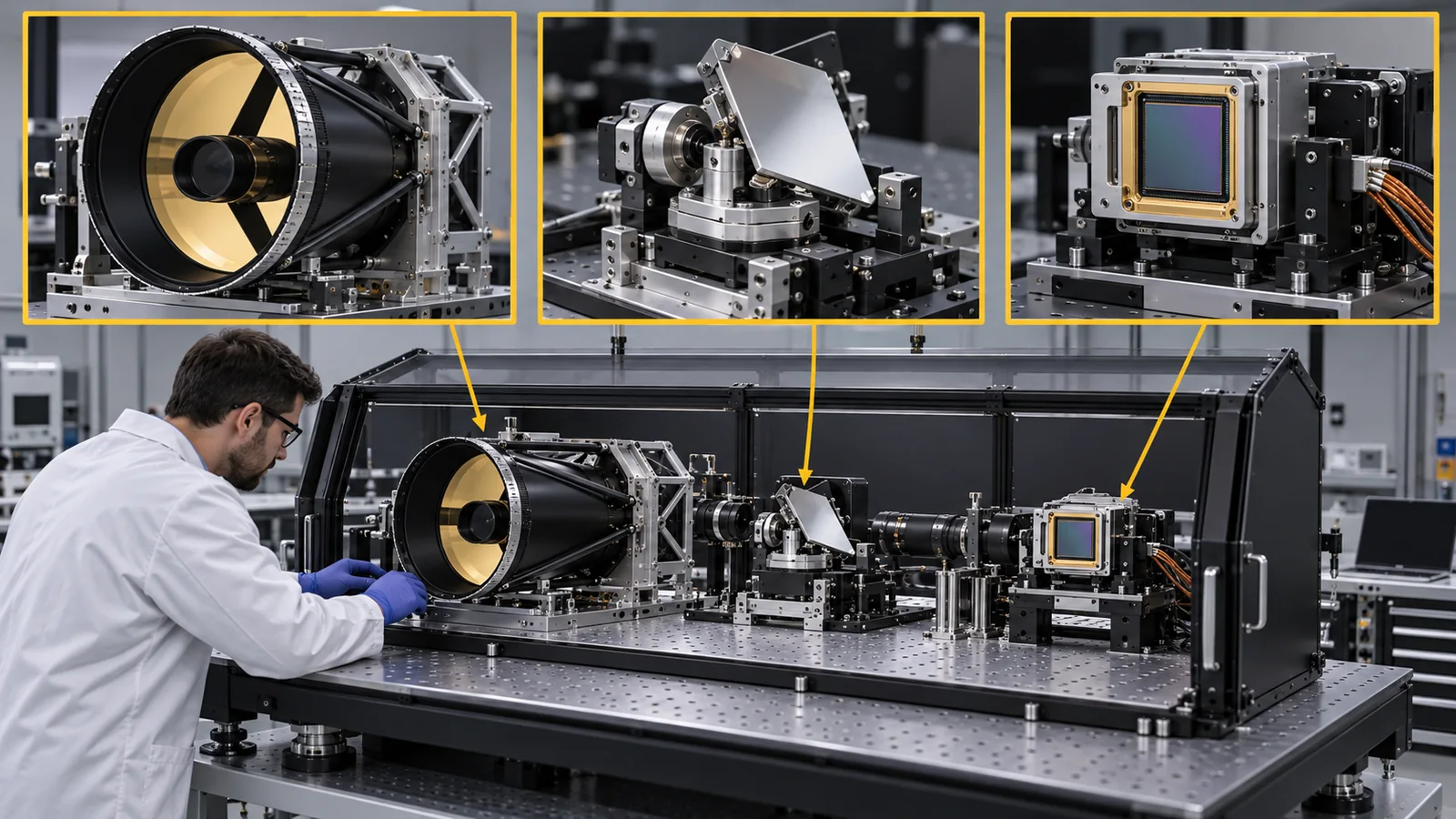
As in Chapter 4, alignment must be held to microradian accuracy. If the telescope barrel, mirrors and optical bench (the base that holds the optics) expand, contract or distort even slightly with temperature, the pointing drifts. In space, temperatures swing widely between sunlight and shadow (see our explainers on spacecraft thermal control and on the space environment and materials). Hence the thermal expansion, heat conduction and weight of bench and mirror materials, and dimensional change from outgassing and moisture release in orbit, decide performance (commentary). This article gives no figures for specific materials, because none could be confirmed in primary sources.
The wavelength of an optical link (1,550 nm, for example) is set by the composition of the semiconductor crystal. The principles of indium-phosphide-based semiconductor lasers and InGaAs photodetectors are in our laser and photodetector explainers. For space use, testing for radiation damage is added. ESA's ESCC publishes guidelines for the evaluation test programme for laser diodes (ESCC 23201 Issue 2), guidelines for laser-diode validation and lot acceptance testing (ESCC 23202 Issue 2), and guidelines for displacement-damage irradiation testing (damage in which particles knock atoms out of the crystal; ESCC 22500 Issue 2) Sourced [ref. 16]. Their texts were not checked; only titles and issues are given.
Within this article we could not confirm from primary sources (1) degradation data for parts after optical links have run for years in orbit, (2) specific figures for the materials and thermal distortion of terminal telescopes and optical benches, (3) an ECSS document specific to optical communication, or (4) the scope of demonstrations behind the CCSDS Orange Books. The EDRS data rate is also not stated, because the ESA pages checked give no figure. A review is Kaushal and Kaddoum (2017) Sourced [ref. 15].
9. How to read the yardsticks and standards
No single speed figure measures an optical link. Read a combination of (1) how much light arrives at what distance (irradiance and link margin), (2) how few errors occur (frame loss and bit error rate), (3) how quickly the light can be aligned (acquisition time), (4) whether it connects to other makers' terminals (compliance with a standard), and (5) whether it resists radiation damage (parts testing).
| What is assessed | Typical test or method (name, source) | Standards and guidance | Reading notes |
|---|---|---|---|
| Irradiance and link margin | Link-budget analysis and testing. SDA requires at least 25 µW/m² at 5,500 km, at most 10 mW/m², and a margin of 3 dB or more in both analysis and test Sourced | SDA OCT Standard v4.0.0 (28 June 2024) and v3.2.0 [ref. 1, 2] Sourced | Numbers without distance or aperture conditions cannot be compared. "Margin" depends on design assumptions |
| Error rate | Frame loss and bit error rate. SDA requires a frame loss of 8×10⁻⁶ (equivalent to a BER of 10⁻⁹) at 25 µW/m² Sourced | SDA OCT Standard v4.0.0 [ref. 1] Sourced / CCSDS 142.0-B-2 coding and synchronisation (March 2026) and 142.10-O-1 (October 2023) [ref. 3, 4] Sourced | A ground link through the atmosphere varies with weather; consider delay including retransmission (ARQ) |
| Acquisition and tracking | PAT acquisition time. SDA requires 100 seconds or less (cold and warm start). ESA describes about 55 seconds for EDRS (GEO to LEO, ~45,000 km), an example and not a standard value Sourced | SDA OCT Standard v4.0.0 [ref. 1], ESA [ref. 5] Sourced | A standard's value and an example's description are on different footings |
| Physical-layer and coding compatibility | Interoperability testing. SDA states interoperability between vendors as the standard's aim. CCSDS Orange Books are experimental specifications Sourced | CCSDS 141.0-B-2 (Blue, March 2026), 141.10-O-1 (Orange, 1550 nm, June 2022), 141.11-O-1 (Orange, 1064 nm, December 2018) [ref. 3, 4] Sourced | CCSDS and SDA standards are separate documents with different wavelengths and schemes; check which one is meant |
| Radiation and life of parts | Total-dose, displacement-damage and single-event tests. For fibre amplifiers, ground irradiation tests (Ma et al.: 50 krad; Zhai et al.: 10 kGy) Sourced | ESCC 23201 Issue 2, 23202 Issue 2, 22500 Issue 2, 22900 Issue 5, 25100 Issue 2 [ref. 16] Sourced | The standards' texts were not checked (titles and issues only). Ground tests and in-orbit life differ |
| Network operation | Standards for the network above the terminal | SDA NEBULA Standard v3.05 (November 2024) [ref. 2] Sourced | The text was not checked. SDA says it includes encryption-device requirements |
| International allocation of optical frequencies | — | Not found (the international treatment of optical frequencies was not checked here) | See the previous article for radio frequencies (ITU and FCC) |
The arrangement of this table is Our calculation (organisation only). SDA figures come from the text of OCT Standard v4.0.0, CCSDS numbers, titles and dates from the CCSDS lists, and ESCC issues from the ESCC list (checked 17 October 2026). The texts of ESCC and CCSDS documents were not checked.
Reading notes for materials engineers
- Ground and bench tests are not in-orbit records: Suncatcher's 800 Gbps was on a ground bench, and the fibre-amplifier radiation tests were ground irradiations. They are not results of years of operation in orbit.
- Company statements are not standard values: Kepler's "SDA-compatible" is a company description, whereas SDA figures are the standard's requirements. Meeting a requirement is not the same as high performance.
- Check whether a standard is advice or a requirement, and which edition: CCSDS Blue Books are standards and Orange Books experimental specifications. The SDA standard is a document for SDA's network. Check the edition (v3.2.0 versus v4.0.0; CCSDS Issue 2 of March 2026).
- Plans are not achievements: Suncatcher's tens of Tbps and Axiom's next on-orbit demonstration are not settled facts.
10. Glossary
- Inter-satellite link (ISL)
- Communication directly between satellites.
- Optical inter-satellite link (OISL)
- An inter-satellite link made with laser light.
- Beam
- A bundle of light or radio focused in one direction.
- Aperture
- The diameter of a telescope or antenna opening.
- Diffraction
- The spreading of waves at an aperture edge, which sets a lower limit on beam spread.
- µrad (microradian)
- A unit of angle, one millionth of a radian; 1 µrad is 1 m at 1,000 km.
- dB (decibel)
- A logarithmic unit for ratios; 10 dB is a factor of 10.
- Photon
- The smallest grain of light.
- Laser source
- A source of single-colour, in-phase light.
- Modulator
- A part that varies the intensity or phase of light to load data on it.
- Optical amplifier
- A part that boosts light as light, for example using fibre doped with a rare earth.
- Photodetector
- A part that turns light into an electrical signal.
- Coherent detection
- A reception method that reads the phase of the light.
- OOK-NRZ
- The simplest modulation, marking 0 and 1 by the presence or absence of light.
- Gbaud
- A billion symbols per second.
- LDPC code
- A type of error-correcting code.
- ARQ (automatic repeat request)
- A scheme that retransmits frames received in error.
- PAT
- Pointing, acquisition and tracking: the actions that align light with the partner.
- Fast steering mirror
- A part that tilts a mirror quickly to correct tiny vibrations.
- Gimbal
- A rotating mechanism that changes the coarse pointing of a telescope or similar.
- Jitter
- Fine shaking of the platform.
- Radiation-induced attenuation (RIA)
- Light weakening because radiation creates defects in glass that absorb it.
- CCSDS
- The Consultative Committee for Space Data Systems, the standards body of space agencies.
- Blue Book / Orange Book
- CCSDS standards (blue) and experimental specifications (orange).
- SDA (Space Development Agency)
- The Space Development Agency of the US Space Force.
11. References
- Space Development Agency (SDA) "Optical Communications Terminal Standard Version 4.0.0" (document ID 9100-001-09, 28 June 2024; approved for public release) — sda.mil/wp-content/uploads/2024/07/SDA_OCT_Standard_4.0.0_final-20240701.pdf
- Space Development Agency (SDA) "Resources" (page listing OCT Standard v3.2.0 and v4.0.0 and NEBULA Standard v3.05; checked 17 October 2026) — sda.mil/home/work-with-us/resources/
- CCSDS Blue Books list: CCSDS 141.0-B-2 "Non-Coherent Optical Communications Physical Layer" and CCSDS 142.0-B-2 "Non-Coherent Optical Communications Coding and Synchronization" (both Issue 2, March 2026) — ccsds.org/publications/bluebooks/
- CCSDS Orange Books (experimental specifications) list: CCSDS 141.10-O-1 (1550 nm, June 2022), 141.11-O-1 (1064 nm, December 2018), 142.10-O-1 (October 2023) — ccsds.org/publications/orangebooks/
- ESA "Laser communications" (EDRS explanatory page) — esa.int/…/EDRS/Laser_communications
- ESA "Relay system speeds vital data flow with 75,000 links" (12 June 2023) — esa.int/…/Relay_system_speeds_vital_data_flow_with_75_000_links
- ESA "Data-relay satellite beams at light speed" (EDRS-C enters service; 16 July 2020) — esa.int/…/Data-relay_satellite_beams_at_light_speed
- Riesing K. et al. (MIT Lincoln Laboratory, NASA) "Operations and Results from the 200 Gbps TBIRD Laser Communication Mission" (NASA Technical Reports Server, 20230007959) — ntrs.nasa.gov/citations/20230007959
- Woodward J. et al. (NASA) "Insights and Observations From Operating A Laser Communication Terminal on the International Space Station (ISS)" (NTRS 20240011025; August 2024) — ntrs.nasa.gov/citations/20240011025
- Israel D. et al. (NASA) "Completion of NASA's Two-Year Laser Communications Relay Demonstration (LCRD) Experiment Program" (NTRS 20240011470; September 2024) — ntrs.nasa.gov/citations/20240011470
- Axiom Space "Axiom Space, Kepler Ready Orbital Computing for Quantum Era" (press release, 6 October 2026) — axiomspace.com/release/axiom-space-kepler-ready-orbital-computing-for-quantum-era
- Beals T. (Google Research) "Exploring a space-based, scalable AI infrastructure system design" (4 November 2025) — research.google/blog
- Ma J. et al. "Experimental investigation of radiation effect on erbium-ytterbium co-doped fiber amplifier for space optical communication in low-dose radiation environment", Opt. Express 17, 15571 (2009) — opg.optica.org/oe/fulltext.cfm?uri=oe-17-18-15571
- Zhai Z. et al. "Radiation-resistant cerium co-doped erbium-doped fibers for C- and L-band amplifiers in a high-dose gamma-radiation environment", Opt. Express 31, 38910 (2023), DOI 10.1364/OE.502917 — doi.org/10.1364/OE.502917
- Kaushal H., Kaddoum G. "Optical Communication in Space: Challenges and Mitigation Techniques", IEEE Commun. Surveys Tuts. 19, 57-96 (2017) (review), DOI 10.1109/COMST.2016.2603518 — doi.org/10.1109/COMST.2016.2603518
- ESCC (ESA) List of published ESCC specifications (ESCC 22500 Issue 2, 22900 Issue 5, 23201 Issue 2, 23202 Issue 2, 25100 Issue 2) — escies.org/specification/listpubspecs
- NIST CODATA 2022 "Planck constant" — physics.nist.gov/cgi-bin/cuu/Value?h
12. Claim-to-source audit
| Claim in the text | Basis | Type |
|---|---|---|
| SDA OCT Standard v4.0.0 (28 June 2024): wavelengths 1553.33 and 1536.61 nm, linewidth 5 GHz or less, centre frequency ±2.5 GHz, transmit power 2.5 W or more and minimum 40 mW or less, divergence 15 µrad or more, 25 µW/m² at 5,500 km, 10 mW/m² or less, frame loss 8×10⁻⁶ (equivalent to BER 10⁻⁹), margin of 3 dB or more, PAT 100 s or less, tracking tone 40 and 50 kHz, OOK-NRZ, LDPC, ARQ, 2.5 Gbaud, theoretical maximum about 2.2 Gbps, burst mode about 49 Mbps (20,000 km), space-to-ground fadeouts, scope | Text of the SDA standard (approved for public release) Reference 1 https://www.sda.mil/wp-content/uploads/2024/07/SDA_OCT_Standard_4.0.0_final-20240701.pdf | Sourced |
| SDA: v3.2.0 intended as the Tranche 3 standard, v4.0.0 adds a new long-range waveform, NEBULA Standard v3.05 (November 2024) | SDA resources page Reference 2 https://www.sda.mil/home/work-with-us/resources/ | Sourced |
| Numbers, titles, dates and summaries of CCSDS 141.0-B-2 and 142.0-B-2 (Issue 2, March 2026), 141.10-O-1 (June 2022), 141.11-O-1 (December 2018) and 142.10-O-1 (October 2023) | CCSDS Blue and Orange Book lists Reference 3 https://ccsds.org/publications/bluebooks/ Reference 4 https://ccsds.org/publications/orangebooks/ | Sourced |
| ESA EDRS: about 45,000 km, 135 mm, about 55 s, relative speed about 8 km/s, about 10 of 100 minutes, contact time about four times, 75,000th link (12 June 2023), over 4.5 PB, ISS since January 2022, EDRS-C launched 6 August 2019 and in service 2020, terminals by Tesat-Spacecom and DLR | ESA pages Reference 5 https://www.esa.int/Applications/Connectivity_and_Secure_Communications/EDRS/Laser_communications Reference 6 https://www.esa.int/Applications/Connectivity_and_Secure_Communications/Relay_system_speeds_vital_data_flow_with_75_000_links Reference 7 https://www.esa.int/Applications/Connectivity_and_Secure_Communications/Data-relay_satellite_beams_at_light_speed | Sourced |
| NASA TBIRD: 6U CubeSat, May 2022, 200 Gbps, up to 4.8 TB, about 5 minutes, coherent transceivers and ARQ. LCRD and ILLUMA-T: up to 1.2 Gbps, geostationary 112 degrees west, the ISS Japanese module, California and Hawaii, LCRD's two-year experiment completed June 2024, ILLUMA-T testing began December 2023 | NASA technical reports (NTRS) Reference 8 https://ntrs.nasa.gov/citations/20230007959 Reference 9 https://ntrs.nasa.gov/citations/20240011025 Reference 10 https://ntrs.nasa.gov/citations/20240011470 | Sourced |
| Axiom / Kepler: 2.5 Gbps, SDA Tranche 1 compatible, first commercial on-orbit demonstration (company claim), 6 October 2026 | Axiom Space press release Reference 11 https://www.axiomspace.com/release/axiom-space-kepler-ready-orbital-computing-for-quantum-era | Sourced |
| Suncatcher bench test: 800 Gbps each way (1.6 Tbps total); tens of Tbps among closely flying satellites (concept) | Google blog Reference 12 https://research.google/blog/exploring-a-space-based-scalable-ai-infrastructure-system-design/ | Not yet confirmed |
| Ma et al. (2009): Er-Yb co-doped fibre amplifier irradiated at 50 krad and 40 rad/s, peak wavelength and half-width unchanged, degradation "a little big", single sample. Zhai et al. (2023): Ce co-doping lowers RIA by more than an order of magnitude, up to 10 kGy at 1.8 kGy/h, 41.6±2.9 dB | Peer-reviewed papers Reference 13 https://opg.optica.org/oe/fulltext.cfm?uri=oe-17-18-15571 Reference 14 https://doi.org/10.1364/OE.502917 | Sourced |
| Numbers, titles and issues of ESCC 23201, 23202, 22500, 22900 and 25100, and the existence of a review (Kaushal and Kaddoum, 2017) | ESCC list; bibliographic record Reference 16 https://escies.org/specification/listpubspecs?pubcode=1&family=1 Reference 15 https://doi.org/10.1109/COMST.2016.2603518 | Sourced |
| The Planck constant used for the photon energy (1.28×10⁻¹⁹ J) | NIST CODATA Reference 17 https://physics.nist.gov/cgi-bin/cuu/Value?h | Sourced |
| Beam spread (15.5 µrad and 20 mrad), widths by distance, received fractions (-44 dB and -92 dB, a difference of about 48 dB or 66,000 times), received power 0.196 µW (-37 dBm), about 1.5×10¹² photons per second and about 610 per symbol, 2.5 W over 85 m giving 438 µW/m² (about 17.5 times) | Our calculation (Python; assuming a 10 cm aperture at 1,550 nm and a 0.5 m dish at 30 GHz for radio) | Our calculation |
| The EDRS data rate, degradation data for parts of optical terminals after years in orbit, figures for materials and thermal distortion of terminal telescopes and benches, an ECSS document specific to optical communication, and the scope of demonstrations behind CCSDS Orange Books | Not confirmed within the scope of this article's survey, so not stated (commentary) | Explanation |
| The readings and explanations "light focuses more tightly than radio", "aiming is the heart of the difficulty", "without standards networks are closed", "microradian accuracy depends on how little materials move" and "glass composition builds radiation tolerance" | This article's own organisation of the published material | Explanation |
Last updated 17 October 2026. Sources are limited to primary material (official documents of SDA, CCSDS, ESA, NASA, ESCC and NIST, peer-reviewed papers and company announcements). Company announcements are treated as company statements and nothing is ranked. The numerical examples are explanatory calculations, not design values of real terminals. Military uses are not discussed. The EDRS data rate, degradation data for parts after years in orbit, figures for telescope and bench materials, and an ECSS document specific to optical communication could not be confirmed and are not stated. The figures are conceptual diagrams or drawings including our calculations; Figs. 1 and 9 are AI-image frames (images not yet placed).