TECHNOLOGY EXPLAINER
Automotive Silicones and Encapsulants
— battery packs and power modules ask different things of a material
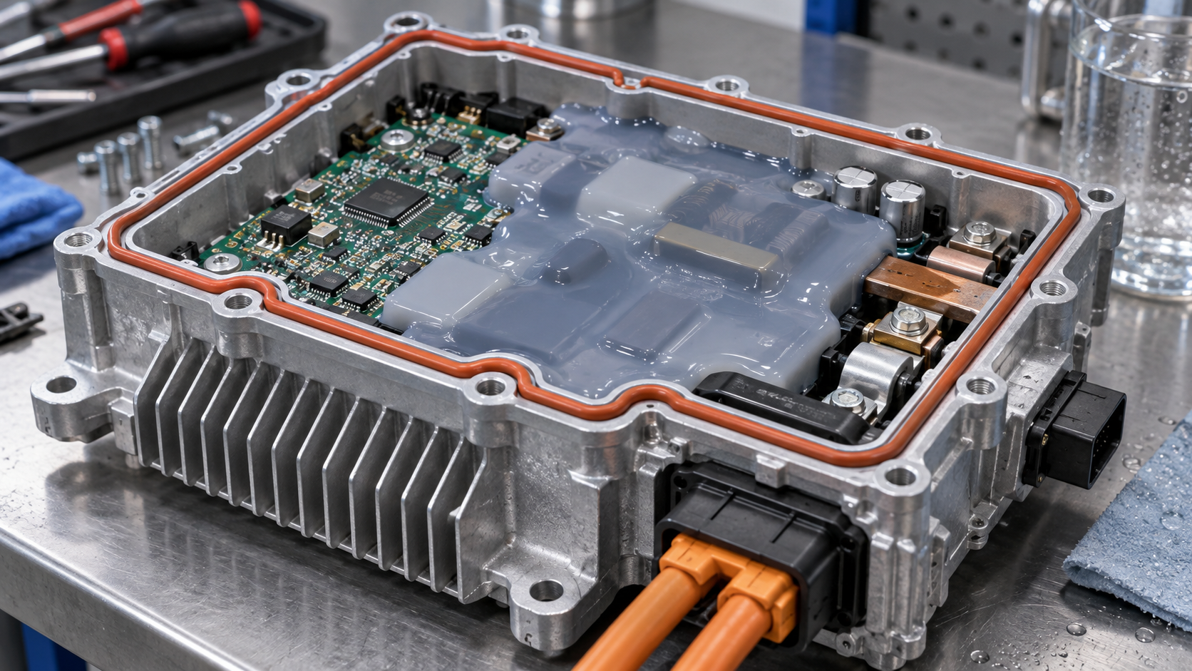
In an EV, silicones, epoxies and other adhesives, encapsulants and potting materials are used in the battery pack, in the power semiconductor modules and in the electronic control units (ECUs). Even when the material is called “silicone”, its job differs: in a battery pack it fixes the cells, carries heat away and slows the spread of thermal runaway; in a power module it protects the chips and wires and relieves stress from temperature cycling. This article uses official manufacturer material and official material from AEC, ECPE, ISO and UL to set out what is used where, and by which tests it is checked. A distinguishing feature of automotive work is that passing the tests as a component or a module comes before any catalogue value of the material.
- What is different in automotive use (the short version)
- Where in an EV, and what is used
- The battery pack: cell fixing, gap fillers and potting
- Thermal runaway and propagation — how much can a material do?
- A materials engineer's view (1): heat-conducting and heat-blocking materials are both needed in one pack
- Power modules: silicone gel and epoxy
- A materials engineer's view (2): higher temperatures pose different questions to gel and to epoxy
- Evaluation: what is checked, by which test
- A materials engineer's view (3): the weight of changing a material
- Open issues, and what this article could not confirm
- Glossary / References / Claim-to-source audit
Sourced = content stated in published material or by a standards body (link given)
Our calculation = a value this article derived from stated assumptions
Not yet confirmed = a plan or target with no confirmed track record
Structural readings and materials-design interpretations are marked separately as Commentary.
Product property values are manufacturers' stated values (typical) and test results are the manufacturer's own tests; values for different grades and conditions are not lined up to rank one against another.
Company names show where a source comes from; they are not a ranking of companies.
1. What is different in automotive use (the short version)
- The demands differ by location. Dow divides its materials for EV battery systems into battery pack assembly, battery fire protection (BFP), protection of electronic control units (ECUs), and busbar and hose insulation Sourced [Reference 1].
- The materials are not only silicones. Dow's battery range also lists thermally conductive polyurethane adhesives, gap fillers and potting foams Sourced [Reference 1].
- Evaluation proceeds through a hierarchy of material, component, module and system. AEC covers components, ECPE's AQG 324 covers power modules, and ISO 16750 covers electric and electronic systems and components (Chapter 8).
Our previous explainer on silicones covered the basics of silicones (the Si–O bond, cure routes, types, low-molecular-weight siloxanes, D4, D5 and D6). This article continues from there and is limited to automotive use. Thermally conductive pastes and gap fillers as such are covered in our explainer on thermally conductive pastes and gap fillers. For encapsulants in general see our explainers on underfill, molding and semiconductor encapsulants; for the thermal-stress formula, coefficient of thermal expansion; for epoxy, epoxy resins; and for polyurethane, polyurethanes and elastomers.
2. Where in an EV, and what is used
The main heat sources and the parts to be protected in an EV are the battery pack, the power modules (the switching devices in inverters and the like) and the control units. Wacker presents its automotive silicones in these groups: thermal interface materials (TIM gap fillers and potting compounds), battery assembly (busbar coatings, seals, valves and coolant connectors), automotive power electronics (sealing and bonding, potting and encapsulation), and battery safety (potting, coating and composite materials) Sourced [Reference 3].
3. The battery pack: cell fixing, gap fillers and potting
For battery systems, Dow lists adhesives, gap fillers, potting foams, encapsulants and thermal materials, and says they support battery pack assembly, battery fire protection, ECU protection and busbar and hose insulation Sourced [Reference 1]. We set out what is published from its page, by role.
| Role | What the sources state | Source |
|---|---|---|
| Cell fixing and assembly | Dow: assembly adhesives bond and secure battery cell components during manufacturing. The thermally conductive polyurethane adhesives (VORATRON MA 8300 series, two-part, 1.2 W/mK) can be used in cell-to-module, cell-to-pack and cell-to-chassis designs and are described as having “bonding strength comparable to structural adhesives” (the manufacturer's claim). Among silicones, the RTV adhesive DOWSIL EA-3838 reaches full fixture time within 20 minutes and needs no oven or primer | [1] |
| Heat transfer (gap fillers) | Dow: DOWSIL TC-5533 is a two-part, 3.0 W/mK low-density gap filler aimed at uses such as battery pack assembly. The polyurethane VORATRON GF 1000 is a two-part, thermally conductive gap filler with very low squeeze force. Wacker: SEMICOSIL 9649 TC is a two-part, addition-cure gap filler of about 4 W/mK for use between power electronics and the cooling system (manufacturer's stated value) | [1] [4] |
| Potting and foam between cells | Wacker: silicone potting covers battery cells, the cell contacting system and the vents and is said to prevent thermal runaway and protect adjacent components. Dow: silicone foams and polyurethane potting foams protect cells and batteries from thermal events | [3] [1] [2] |
| Seals and gaskets | Dow: the DOWSIL 3-8259 RF silicone foam kit is two-part and room-temperature curing, dispensed onto parts to form an integrated compression gasket. Liquid silicone rubber (SILASTIC LSR) is intended for integrated seals and electrical connectors and housings | [1] |
| Busbars and covers | Wacker: ELASTOSIL R 531/60 is an extrudable silicone rubber that insulates busbars in high-voltage batteries and ceramifies in a fire, keeping its insulation and preventing a short circuit (the manufacturer's description). ELASTOSIL CM 145 is a sprayable ceramifying coating for battery covers | [4] [3] |
All Sourced (manufacturers' stated values and descriptions; products are examples and do not imply a ranking; check each company's material for the test conditions behind the thermal conductivities).
Within a single battery pack, then, the separate roles of bonding, heat conduction, insulation, flame resistance and sealing are assigned to separate materials. The next chapter looks at the one that weighs most in design, preparation for thermal runaway, through the manufacturers' own explanations and how to read their tests.
4. Thermal runaway and propagation — how much can a material do?
In battery safety, the heaviest job for materials is preparing for thermal runaway. The Dow technical paper divides its safety concerns into two Sourced [Reference 2].
- A single cell going into thermal runaway. It names an internal short circuit, overheating or overcharging, and impact or penetration as causes, and says manufacturing defects or long-term failure mechanisms such as dendrite growth perforating the separator are also possible. The result can be a violent reaction with gas pressure, flame and heat, in which the vent or case ruptures and flame, hot gases and particles reach adjacent cells.
- That heat spreading to neighbouring cells in a chain (thermal propagation). If enough heat is generated, the adjacent cells go into thermal runaway themselves, creating a chain reaction.
Dow's paper describes China's standard GB 38031-2020 as stating that no external fire, explosion or smoke should enter the passenger compartment within five minutes of a battery cell thermal event being detected in a module or pack. It says the aim is to give occupants time to escape and first responders time to contain the fire, that similar standards are being developed for other geographies, and that some OEMs set internal targets that go beyond them Sourced [Reference 2]. This article has not checked the text of GB 38031-2020. The above is as written in Dow's paper.
What materials can do: a “second line of defence”
Dow's paper sets out three ways to reduce thermal runaway and thermal propagation Sourced [Reference 2].
- Remove the possibility of thermal runaway at cell level. Cell chemistry and design keep improving, but they are unlikely to eliminate the risk of thermal runaway.
- Use battery fire protection (BFP) materials in module and pack assembly as a “second line of defence”. In and around cells and within modules and packs, to contain or mitigate a thermal runaway event and prevent propagation.
- Use barrier materials at module or pack level, inside and outside.
The role given to materials is not to “eliminate” thermal runaway but to “slow its spread”. Wacker likewise states its goals as, in thermal runaway, to interrupt pathways and stop heat transfer and, in thermal propagation, to limit damage and prevent fire from breaching adjacent battery components Sourced [Reference 3].
The Dow technical paper lists these advantages of silicones Sourced [Reference 2] (the manufacturer's own claims).
- Easy to apply or dispense, and they generate negligible heat when curing, which protects cells during assembly.
- They give cells strength, stability and protection in operation and survive many charge and discharge cycles.
- Because the Si–O bond is strong, silicones are more thermally stable than organic materials. At extreme temperatures (thermal runaway) they decompose mostly to silicon dioxide (silica), which remains electrically insulative, whereas organic materials combust and release large volumes of decomposition gas that can add fuel to a fire.
- Organic materials can be engineered with a very high crosslink density to limit weight loss, but these tend to be brittle and leave a carbon-based char that is not electrically insulating at high temperature. Some organic materials also release toxic by-products on decomposition.
These are the manufacturer's comparative claims. Comparative figures against specific organic materials, grades and test conditions could not be confirmed in this article. That Dow's battery range also includes polyurethane potting foams [Reference 1] shows that organic materials are used as well, depending on the use and conditions (Commentary).
Forms of material, and published typical values
Dow sorts the silicones relevant to BFP into liquid silicone rubber (LSR), high-consistency silicone rubber (HCR), silicone foam and silicone resin, and gives typical properties in a table.
| Form | What the sources state (Dow technical paper) |
|---|---|
| LSR (liquid) | Cure time 1 to 15 min, viscosity 1 to 10 Pa·s, density 1.1 to 1.4 g/cm3, thermal conductivity 0.3 to 1 W/m·K, compressibility “good”, flame resistance “very good”. Used as potting compounds or low-modulus gels to fill the gaps between cells, to encapsulate electronic and electric components so they are isolated from each other during a cell failure, and in normal operation to protect them from mechanical vibration and other abuse. Can also be applied as a coating on a pack cover and cured |
| Silicone foam | Cure time 2 to 15 min, viscosity 1 to 10 Pa·s, density 0.1 to 0.5 g/cm3, thermal conductivity below 0.1 W/m·K, compressibility “excellent”, flame resistance “very good”. Two-part, based on LSR or HCR, dispensed and cured in place or made into prefabricated sheets. Also used for gaskets (FIPFG). Sheets are used for vibration damping between cells and for compression sustained through charging and ageing |
| HCR (high-consistency) | Heat-cured with peroxide. Cure time 0.5 to 5 min, density 1.1 to 1.5 g/cm3, thermal conductivity 0.3 to 1 W/m·K, compressibility “good”, flame resistance “excellent”. Its high viscosity rules out liquid dispensing, so it suits moulded parts and extruded profiles. A sheet exposed to flame for five minutes ceramifies at the surface, and the porous ceramic layer has significantly lower thermal conductivity than the HCR before exposure, so it suits insulation layers between modules or cells |
| Silicone resin | Rich in T and Q units with a tight network. Has the best flame resistance and thermal stability among silicones. Cured resin can reach a Young's modulus above 1 GPa without fillers. Dow says the M, D, T and Q compositions allow any modulus from that typical of silicone elastomers (0.1 to 2 MPa) up to a rigid resin. Forms a ceramic layer under flame and is used in coatings that resist penetration by flame and hot particles |
All Sourced (Dow's typical values and descriptions; the test conditions are not given in the paper and could not be confirmed. The values are Dow's own and are not a comparison with other companies' products or other kinds of material).
Wacker uses thin, flexible thermal barriers (the ELASTOSIL CM series, which perform very well in thermal propagation tests) and rigid barriers (silicone-resin-based laminates and fibre-reinforced composites that keep working in a fire and can form a protective ceramic layer) Sourced [Reference 3].
The manufacturer's own test: the mini-module test
For screening materials, the Dow paper recommends a hierarchical approach: material properties → flame exposure (UL 94, or higher-energy tests including a high-temperature flame with a particle blast) → high-temperature thermal conduction test → cell-to-cell tests → mini-module (cell cluster) tests → full module or pack tests Sourced [Reference 2]. It describes an example of the mini-module test as follows.
- Set-up: nine commercial 18650 cylindrical cells in a 3 × 3 array in a canister, with a cell spacing of 0.8 mm (it gives 0.8 to 2.0 mm as the range usual in real modules), and the centre cell forced into thermal runaway by overheating.
- Control: an unpotted test with nothing filled in. In several control tests, thermal runaway in the centre cell caused thermal propagation to the remaining cells.
- Result with silicone foam: the centre cell ignited at about 130 °C and reached more than 750 °C overall. The adjacent cells reached about 120 °C in the cross positions (2, 4, 6, 8) and about 100 °C in the corners (1, 3, 7, 9), and the canister lid reached 280 °C. No thermal propagation occurred.
Dow presents this result as an example in which the silicone encapsulant insulated the cells and prevented thermal propagation. But the same paper also says that the temperature and time thresholds are usually set by the customer, and that the cell type (cylindrical, prismatic or pouch) governs which BFP material forms are suitable Sourced [Reference 2]. This result should therefore be read as the result of a screening test under specific conditions (Commentary).
Dow's test hierarchy includes UL 94 [Reference 2]. UL Solutions explains that UL 94 is a small-scale test that evaluates plastic materials against a small flame or radiant heat under controlled laboratory conditions. The horizontal burn (HB) and vertical burn (V-0, V-1, V-2) ratings are set by applying a 3/4-inch, 50 W burner flame to a specimen of about 5 × 1/2 inch. Most UL 94 results are said not to apply to materials more than 13.0 mm thick or with a surface area above 1 m2 Sourced [Reference 17].
A rating such as UL 94 V-0 therefore does not guarantee a countermeasure against thermal runaway (Commentary). It is an indicator for the first stage of material screening, to be checked separately by cell-to-cell, mini-module and pack tests (the intent of Dow's hierarchy).
5. A materials engineer's view (1): heat-conducting and heat-blocking materials are both needed in one pack
Inside a battery pack there are places where heat should leave quickly and places where heat should not be passed on. The published typical values make the difference clear Sourced [References 1, 2, 4].
- Between cell and cold plate (let heat out): gap fillers. Dow DOWSIL TC-5533 is 3.0 W/m·K and Wacker SEMICOSIL 9649 TC is about 4 W/m·K (both manufacturers' stated values).
- Between cells (do not pass heat on): silicone foam. Dow's typical value is below 0.1 W/m·K. LSR is 0.3 to 1 W/m·K.
The ratio of the gap filler's thermal conductivity to the foam's is 3.0 ÷ 0.1 = 30 times or more and 4 ÷ 0.1 = 40 times or more Our calculation (the foam value is “below 0.1”, so the real ratio is larger still; it is a ratio of values from different sources and test conditions, not a same-condition comparison).
Even within one family of materials, they are made to conduct heat when highly filled and to block it when they contain gas cells (Commentary). The knack of design is to decide, as a matter of material placement, “where to conduct heat and where to stop it”. The conducting side is covered in our explainer on thermally conductive pastes and gap fillers.
Our calculation: how much do foam and LSR differ in mass when filling the space between cells?
A difference in density leads directly to a difference in battery pack mass. Using the same layout as Dow's mini-module test (a square array of 18650 cells, 0.8 mm spacing), we estimate the gap volume per cell and the mass needed to fill it Our calculation.
- Assumptions: an 18650 cell is a cylinder 18 mm in diameter and 65 mm long (the dimensions the name implies). Square array with pitch = 18 + 0.8 = 18.8 mm. The gap is assumed to be completely filled (in practice there is also space above, below and around the cells and it is not filled completely).
- Gap cross-section: 18.82 = 353.4 mm2 and cell cross-section π × 92 = 254.5 mm2. The difference is about 99.0 mm2 (a gap fraction of about 28%).
- Gap volume per cell: 99.0 mm2 × 65 mm = about 6.4 cm3.
- Mass: foam (0.1 to 0.5 g/cm3) gives about 0.64 to 3.2 g and LSR (1.1 to 1.4 g/cm3) gives about 7.1 to 9.0 g.
- Per 1,000 cells: foam about 0.64 to 3.2 kg, LSR about 7.1 to 9.0 kg.
Assumptions and limits: real battery packs use hexagonal arrays and have gaps above, below and around the cells, and they are not completely filled. Dow's LSR density of 1.1 to 1.4 g/cm3 is a typical value that includes the spread from formulation. What can be said is the direction, “foam is lighter”, and the rough order of magnitude; computing pack mass needs the data sheet value for each product and the actual fill quantity.
6. Power modules: silicone gel and epoxy
A power module, which switches electric power in an inverter and the like, is generally a structure in which power semiconductor chips sit on a ceramic substrate, are wired with bond wires and the like, and are joined to a cooler (this article's description). ECPE's AQG 324 says of such modules that most designs are not hermetically sealed and that the semiconductor chips and bonding wires are embedded in, for example, a silicone gel that is permeable to humidity Sourced [Reference 10]. There are broadly two ways of encapsulating (our organisation).
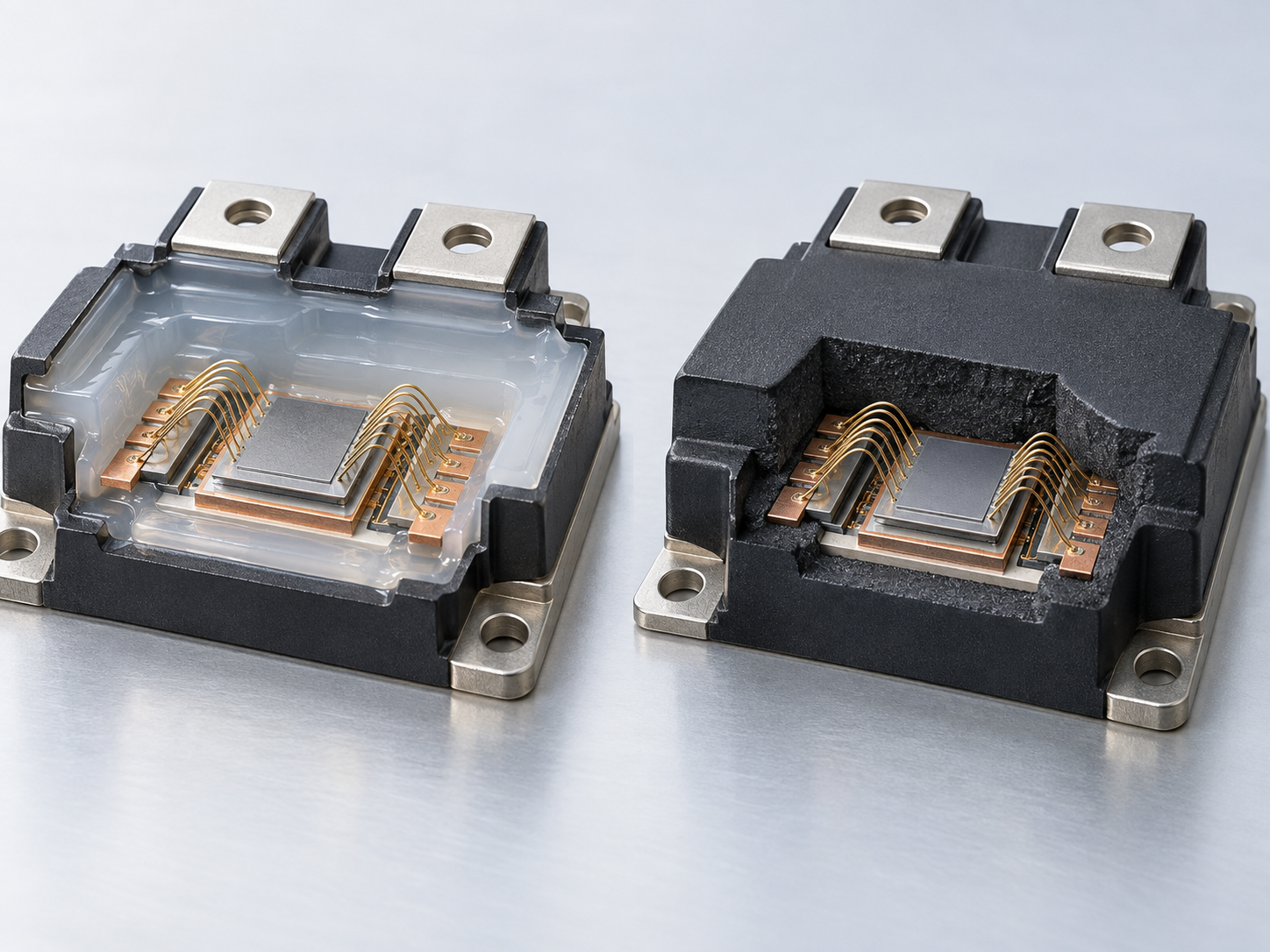
(1) Gel: softness that relieves stress
Dow's September 2025 announcement says that EV battery voltages are rising from 400 V to 800 V and that, with 7th-generation IGBT modules, junction temperatures rise, so a silicone gel needs strong dielectric properties and higher heat resistance Sourced [Reference 5]. Its DOWSIL EG-4175 silicone gel is said to withstand up to 180 °C, absorb vibration, self-heal small cracks, have adhesion without a primer (self-priming) and cure at room temperature (with heat acceleration possible), and to have low silicone oil bleed (all the manufacturer's claims) Sourced [Reference 5].
Dow's selection guide contrasts gels as offering “maximum stress relief and self-healing” with encapsulants as “more resistant to abrasion and damage, and easily repairable”. Most of the encapsulants and gels in its range are two-part addition-cure silicones; most gels have a tacky surface that adheres to common surfaces without primers. Encapsulants come as standard grades (a priming step is needed if strong adhesion is wanted) and as self-priming grades that adhere to many surfaces when cured above 100 °C, with hardness in the range Shore 00 20 to Shore A 65. It also claims that silicones, in general, need no oven to dry parts, as urethanes do, and raise no exotherm concern, as epoxies can Sourced [Reference 6].
(2) Epoxy moulding compound: protecting by stiffness
Sumitomo Bakelite says that SiC power semiconductors can operate above 200 °C but that encapsulation materials have fallen short on heat resistance, and on 1 June 2026 it announced the start of mass production of the solid epoxy moulding compound SUMIKON EME-G785 series Sourced [Reference 7]. Its explanation is as follows.
- Raising the Tg of an epoxy moulding compound above 200 °C generally raises crosslink density and so the elastic modulus (stiffness). This is a trade-off: thermal stress in heat cycling can cause delamination and cracks, and a high Tg, though possible in theory, has been hard to use in practice.
- G785 raises Tg by stiffening the polymer backbone and optimising crosslink density and uses low-stress technology to hold back the rise in modulus, reducing warpage and preventing delamination from chips and substrates and resin cracking.
- In the company's comparison table, Tg is 195 °C for G720 and G780 and 230 °C for G785. Weight loss at 250 °C for 1,000 hours is above 2% for G720 and below 2% for G780 and G785.
- The higher heat resistance is said to allow sintered materials and solder bonding to cooling parts, helping heat dissipation.
The company positions G785 as a strategic product for next-generation power electronics and aims for sales of ¥10 billion by fiscal 2030 Not yet confirmed [Reference 7]. Note that another page of the company (on moulding compounds for power control modules) gives the Tg of G785 as 240 °C and also lists adhesion (Ni) and dielectric strength [Reference 8]. We could not confirm why the Tg figures differ between the two pages (measurement method, revision and so on) (Chapter 9).
| Aspect | Gel encapsulation (case type) | Epoxy moulding (transfer moulding) |
|---|---|---|
| Form of material | Two-part addition-cure silicone poured as a liquid and cured [6] | Solid epoxy moulding compound moulded with heat [7] |
| Hardness and stress | Gel gives maximum stress relief; encapsulants resist abrasion [6] | Raising Tg also raises the elastic modulus; delamination and cracking in heat cycling are the issue [7] |
| Published heat resistance | EG-4175: up to 180 °C [5]. KE-1066: −40 to 200 °C (service range) [18] | G785: Tg 230 °C (announcement) or 240 °C (product page). Weight loss (250 °C/1,000 h) below 2% [7] [8] |
| Repair | Encapsulants are easily repairable and gels claim self-healing [6] [5] | Not stated in the sources we checked |
| Moisture | Gel is permeable to humidity, which reaches the passivation layer [10] | Not stated in the sources we checked |
| Published insulation value | KE-1066: dielectric breakdown strength 16 kV/mm (23 °C) [18] | G720, G780, G785: 21 to 22 kV/mm [8] |
All Sourced (manufacturers' stated values and the guideline's statements). Products, test conditions and measurement methods differ, so the values are not lined up to rank one against another. The test conditions for the dielectric breakdown strengths could not be confirmed on the pages.
7. A materials engineer's view (2): higher temperatures pose different questions to gel and to epoxy
As SiC adoption and 800 V systems raise the junction temperature of modules, the heat-resistance requirement on the encapsulant grows. But for gel and for epoxy, the substance of the difficulty differs (Commentary).
- For gel, the challenge is keeping softness and adhesion when hot. To withstand a higher junction temperature, Dow gives EG-4175 a heat resistance of 180 °C and states primerless adhesion and low oil bleed alongside it [5]. Shin-Etsu Chemical's KE-1066 also lists good adhesion to the substrate even at high temperature as a feature [18]. Managing the bleeding low-molecular-weight component connects with the earlier explainer's account of low-molecular-weight siloxanes.
- For epoxy, the challenge is raising Tg without raising the modulus. Sumitomo Bakelite states this plainly as a trade-off [7]. Apply it to the thermal-stress formula in our explainer on coefficient of thermal expansion (elastic modulus × difference in expansion coefficient × temperature difference) and a higher modulus means more stress for the same temperature difference.
- The entry point of evaluation differs. Gel is permeable to humidity and moisture reaches the chip surface, so tests such as H3TRB (high-humidity, high-temperature reverse bias) weigh heavily [10]. For epoxy moulding compounds, delamination and cracking are looked at after heat cycling by acoustic microscopy and the like (AEC-Q101 includes acoustic microscopy inspection after TC [12]).
Our calculation: set the test temperature span against the materials' published temperatures
We place the test temperature spans and the materials' published temperatures on one temperature axis and calculate the temperature difference (ΔT) Our calculation.
Assumptions and limits: the AEC-Q101 temperature cycle has a lower limit of −55 °C and an upper limit of the part's maximum rated junction temperature (not exceeding 150 °C), and can be shortened to 400 cycles under some conditions [Reference 12]. The 205 K in the figure is the maximum, for an upper limit of 150 °C. The AQG 324 thermal shock test, on the other hand, runs from −40 °C to +125 °C with a dwell of more than 15 minutes [Reference 10]. The materials rows are published values of differing character: the range Wacker's gap filler withstands in thermal shock, the service range of Shin-Etsu Chemical's gel, the generic statement in Dow's selection guide (sustained temperature), and EG-4175 (upper limit only). All we can say is that the materials' published temperature spans lie at or above the span of the tests, a plain organisation of facts (Commentary).
8. Evaluation: what is checked, by which test
Automotive evaluation has different standards and guidelines for each level of object. The figure below arranges what we could confirm from official material in order of the size of the object.
| Standard or guideline | What the sources state | Source |
|---|---|---|
| AEC-Q100 / Q101 / Q104 / Q200 | Common qualification requirements for electronic components set by the technical committee of the AEC (Automotive Electronics Council). Q100 (Rev J1) for integrated circuits, Q101 (Rev E) for discrete semiconductors, Q104 (Rev A) for multichip modules, Q200 for passive components. “Components meeting these specifications are suitable for use in the harsh automotive environment without additional component-level qualification testing” | [11] |
| AEC-Q101 Rev E (1 March 2021) | Its purpose is to determine that a part is capable of passing the specified stress tests and so can be expected to give a certain level of quality and reliability in the application. Temperature cycling (TC): 1,000 cycles, from −55 °C to the maximum rated junction temperature (not exceeding 150 °C), JEDEC JESD22-A104. H3TRB: 85 °C/85% RH, 1,000 hours, reverse bias at 80% of rated breakdown voltage (up to 100 V), JESD22-A101. UHAST: 96 hours at 130 °C/85% RH (or 264 hours at 110 °C). Autoclave: 96 hours at 121 °C, 100% RH, 15 psig. Acoustic microscopy inspection after TC (J-STD-035) to look for delamination. Each test uses 77 parts per lot, 3 lots, with zero failures accepted | [12] |
| ECPE AQG 324 Release 04.1/2025 | Sets requirements, test conditions and tests for power modules for power electronics converter units in motor vehicles (up to 3.5 t gross weight). It covers the module design and the qualification of devices at module (assembly) level, and not the qualification of semiconductor chips or manufacturing processes. It does not replace the qualification tests for complete vehicle converter units. The main document is for Si, with SiC in an annex. It originated in the German supply specification LV 324 | [9] [10] |
| AQG 324 environmental and lifetime tests | Thermal shock (QE-01): IEC 60749-25:2003, −40 to +125 °C, dwell over 15 min, thermal resistance (Rth,j-c) added to the failure criteria, acoustic microscopy for delamination recommended. Vibration (QE-03): IEC 60068-2-6 (sinusoidal) and IEC 60068-2-64 (wide-band random), profiles by mounting location (A: engine-mounted, B: transmission-mounted, D: sprung masses), 6 devices. H3TRB (QL-07): 1,000 hours or more, 85 °C/85% RH, junction temperature 81 to 90 °C, 0.8 × maximum voltage. Power cycling (QL-01 PCsec, QL-02 PCmin): on-times under 5 s stress the chip-near interconnections (die attach, top-side contacts); over 15 s also stress the cooling-side soldering | [10] |
| ISO 16750 series (2023 editions) | Part 1 (general), Part 3 (mechanical loads), Part 4 (climatic loads), Part 5 (chemical loads). All apply to electric and electronic systems and components, including electric propulsion systems and components of voltage class B (high voltage), and specify environmental stresses by mounting location with tests and requirements. All are at the revision stage (90.92), with the next editions in preparation. Part 1 has 22 pages, Part 3 104, Part 4 59 and Part 5 9 (Part 5 is the third edition, the others the fourth) | [13] [14] [15] [16] |
All Sourced (statements of the standards bodies and guideline owners. The full texts of some standards are paid, so for ISO 16750 we limit ourselves to scope statements; check the latest editions for details of test conditions).
AQG 324 states the purpose of H3TRB as finding weak points in the overall module structure and explains it as follows [Reference 10].
- The chips and wires are embedded in silicone gel permeable to humidity, so water reaches the passivation layer over time.
- The focus is on the interaction of production-related ionic contaminants, which migrate under humidity, temperature and fields, with thermomechanical stress on the housing and corrosive gases.
- The module assembly process and the coefficients of thermal expansion (CTE) of the materials also have a significant influence on the integrity of the passivation, and mechanical stress generally raises the sensitivity to (electro-)chemical corrosion.
As seen in the previous explainer on silicones, silicone is a material that passes water vapour even though it does not absorb water. The gel's permeability, the stress the gel applies and the impurities (ions) in the gel can all influence the result of this test (Commentary).
9. A materials engineer's view (3): the weight of changing a material
The AEC documents cover components, and AQG 324 covers modules [References 10, 11]. The unit of qualification in automotive work is not an “AEC-qualified material” for an encapsulant or gel as such, but the component or module that uses it passing the tests (Commentary; within what we checked, we found no automotive standard that qualifies an encapsulant alone).
From this premise, changing a material carries weight. Annex I.B of AQG 324 contains a change-control matrix (DeQuMa). Based on a ZVEI guideline for change notification, it links the type of change to the tests that should be reconsidered. Some of its rows are as follows Sourced [Reference 10].
- PM-PA-13: change of mold compound / encapsulation / potting material
- PM-PA-14: change of molding / encapsulation / potting process
- PM-PA-15: change in sealing or adhesive material
- PM-PA-21: change of thermal interface material or joining technology, and others
Each cell of the matrix carries a category: X (performance of that stress test should be considered), R (module- or assembly-specific risk assessment) or G (carry-over of generic data) [Reference 10]. We do not show which tests carry an X, because we could not ensure the accuracy of reading them. Even so, the fact that a change of encapsulant, potting material or adhesive is listed as an independent item in change control itself shows the weight of changing a material (Commentary).
AQG 324 also asks that the design record show, for solid insulating materials and gels, their properties in the specified temperature range and the long-term influence of temperature, humidity and mechanical pressure, and says that the composition alone is sufficient to name a material, without the manufacturer or type designation [Reference 10]. For a materials maker, data on the long-term influence of temperature, humidity and pressure thus connect directly to the customer's design record (Commentary).
10. Open issues, and what this article could not confirm
(1) The text of the standards
We checked the published documents for AEC-Q101 and AQG 324, but ISO 16750 is a paid standard, so we limit ourselves to its scope, edition and page counts and have not checked the test conditions. The German OEM specification LV 124 appears only as the origin of the vibration profile names in AQG 324, and we have not checked its text. For China's GB 38031-2020 as well, we have not checked the text and quote Dow's description.
(2) The effect of thermal-runaway measures
The mini-module result is Dow's own test, in a specific configuration. Comparisons with other companies' materials, results for a whole real-vehicle pack, and independent confirmation could not be confirmed here. Statements of “track record” and “adoption” (such as Dow's “adopted by OEMs over the last decade”) are treated as the manufacturer's claims, and we have not confirmed specific models or volumes.
(3) A discrepancy in figures
Sumitomo Bakelite gives the Tg of G785 as 230 °C in its announcement (1 June 2026) and as 240 °C on its product page, and we could not confirm why. Both are shown as manufacturer's stated values, and we make no judgement of ranking or correctness.
(4) Details of material properties
The test methods and conditions behind the gap fillers' thermal conductivity are not stated in the material, so we could not confirm them (we show them only as manufacturers' stated values). Specific values for the elastic modulus and thermal expansion coefficient of gels and epoxies could not be confirmed in a form fit for an automotive comparison.
(5) What is out of scope
The details of heat conduction for gap fillers, thermal pads and TIMs are left to other explainers and are not covered here. For chemical regulation (D4, D5, D6 and so on) see the previous explainer on silicones. We do not cover pack structure (cooling methods, designs for each cell type) or the recycling viewpoint.
- In a battery pack, bonding, heat conduction, insulation, flame resistance and sealing are assigned to different materials. Polyurethanes are used as well as silicones Sourced
- The role of the material is not to “eliminate” thermal runaway but to slow its spread. Dow says cell improvements alone cannot remove it and calls materials a “second line of defence” Sourced
- Heat-conducting materials (3.0 to about 4 W/m·K) and heat-blocking ones (below 0.1 W/m·K) are both needed in one pack. The ratio is 30 times or more Our calculation
- In power modules, gel relieves stress and epoxy protects by stiffness. The trade-off between high Tg and low modulus is the issue Sourced
- Gel passes humidity. H3TRB (85 °C/85% RH, 1,000 hours or more) is a test tied directly to a property of the material Sourced
- The unit of automotive qualification is the component or module, not the material. A change of encapsulant or potting material is an independent item in AQG 324's change control Sourced
- UL 94 V-0 does not guarantee a thermal-runaway countermeasure. It is a small-scale material test Sourced
11. Glossary
- Thermal runaway
- A cell going into uncontrolled heating, triggered by an internal short, overheating, overcharging, impact and so on.
- Thermal propagation
- Heat from one cell's thermal runaway reaching neighbouring cells and setting off a chain.
- BFP
- Battery fire protection. Materials and structures that mitigate thermal runaway and propagation.
- Gap filler
- A paste-like or elastic material that fills the gap between a heat-generating part and a cooling member and conducts heat.
- Potting
- Pouring a liquid material around a part and curing it to hold and protect the part.
- Ceramification
- The property by which silicone exposed to flame becomes a hard, silica-based ceramic layer. It insulates electrically and thermally.
- LSR / HCR
- Liquid silicone rubber / high-consistency (solid) silicone rubber.
- Power module
- A part that mounts power semiconductors such as IGBTs and MOSFETs on a substrate. Used in inverters.
- IGBT
- Insulated-gate bipolar transistor. A power semiconductor used to switch large currents.
- SiC
- Silicon carbide. A power semiconductor material strong at high temperature and voltage.
- EMC
- Epoxy molding compound. A solid resin moulded with heat to encapsulate semiconductors.
- Tg
- Glass transition temperature. A guide to where a material changes from a hard glassy state to a rubbery one.
- H3TRB
- High-humidity, high-temperature reverse bias test. Applies a reverse voltage at 85 °C and 85% RH to look for moisture-driven degradation.
- AEC-Q101
- The AEC's qualification requirements for automotive stress testing of discrete semiconductors.
- AQG 324
- ECPE's qualification guideline for automotive power modules.
- DeQuMa
- The change-control matrix in an annex of AQG 324 that links a type of change to the retests to be considered.
- ISO 16750
- A series of standards for the environmental conditions and testing of electric and electronic equipment in road vehicles.
12. References
- Dow “Battery Systems” (materials for EV battery systems) https://www.dow.com/en-us/market/mkt-mobility/sub-mobility-electronics/app-mobility-elec-battery-systems.html
- Dow technical paper “Silicone Material Solutions for Battery Fire Protection” (Form No. 80-8541-01-0825, PDF) https://www.dow.com/documents/80/80-8541-01-silicone-material-solutions-for-battery-fire-protection.pdf
- Wacker “Improving battery safety with silicones” https://www.wacker.com/cms/en-us/products/insights/silicone-battery-safety.html
- Wacker press release “Battery Show Europe 2025 WACKER presents new gap filler for electromobility”, 2 June 2025 https://www.wacker.com/cms/en-us/press-and-media/press/press-releases/2025/press-releases-detail-2025-254913.html
- Dow press release “Dow launches DOWSIL™ EG-4175 Silicone Gel to enable higher voltage power electronics in electric vehicles and renewable energy technologies”, 4 September 2025 https://corporate.dow.com/en-us/news/press-releases/dow-launches-dowsil-eg-4175-silicone-gel.html
- Dow “Encapsulants and gels selection guide” (Form No. 11-3922-01-1123, PDF) https://www.dow.com/documents/11/11-3922-01-silicone-encapsulants-and-gels.pdf
- Sumitomo Bakelite “Development of High-Tg Epoxy Molding Compounds for Next-Generation SiC Power Modules”, 1 June 2026 https://www.sumibe.co.jp/english/topics/2026/it-materials/0428_01/index.html
- Sumitomo Bakelite “Special Molding Compound for Power Control Module” https://www.sumibe.co.jp/english/solution/mobility/electric_vehicle/power_module.html
- ECPE “Automotive AQG 324” (working group page) https://www.ecpe.org/research/working-groups/automotive-aqg-324/
- ECPE ECPE Guideline AQG 324 “Qualification of Power Modules for Use in Power Electronics Converter Units in Motor Vehicles”, Release 04.1/2025 (release date 31 March 2025, PDF) https://www.ecpe.org/index.php?eID=dumpFile&t=f&f=46275&token=0d6454cead46e7321e58907672861b3fcd13c0c0
- AEC Automotive Electronics Council “AEC Documents” http://www.aecouncil.com/AECDocuments.html
- AEC AEC-Q101 Rev-E “Failure Mechanism Based Stress Test Qualification for Discrete Semiconductors in Automotive Applications”, 1 March 2021 (PDF) http://www.aecouncil.com/Documents/AEC_Q101_Rev_E_Base_Document.pdf
- ISO ISO 16750-1:2023 “Road vehicles — Environmental conditions and testing for electrical and electronic equipment — Part 1: General” https://www.iso.org/standard/77578.html
- ISO ISO 16750-3:2023 “… Part 3: Mechanical loads” https://www.iso.org/standard/77579.html
- ISO ISO 16750-4:2023 “… Part 4: Climatic loads” https://www.iso.org/standard/77580.html
- ISO ISO 16750-5:2023 “… Part 5: Chemical loads” https://www.iso.org/standard/77581.html
- UL Solutions “Understanding UL 94 Rating Certifications and Limitations” (Code Authorities, 15 July 2019) https://code-authorities.ul.com/about/blog/understanding-ul-94-rating-certifications-and-limitations/
- Shin-Etsu Chemical “Highly thermostable silicone gel” (KE-1066-A/B) https://www.shinetsusilicone-global.com/products/notice/165/index2.shtml
13. Claim-to-source audit
| Claim in the text | Basis | Label |
|---|---|---|
| Dow's materials for battery systems (adhesives, gap fillers, potting foams, encapsulants, thermal materials; battery pack assembly, BFP, ECU protection, busbar and hose insulation). That assembly adhesives secure cell components during manufacture. VORATRON MA 8300 (two-part, 1.2 W thermally conductive polyurethane adhesive; cell-to-module, pack and chassis), GF 1000 (polyurethane gap filler), potting foam (polyurethane). DOWSIL TC-5533 (two-part, 3.0 W/mK, low density), 3-8259 RF (silicone foam kit; integrated compression gasket), EA-3838 (RTV adhesive; fixture within 20 minutes, no oven or primer), SILASTIC LSR (integrated seals, connectors), TC-4060 (thermal gel for ECUs). Protection of ECUs and BMS | Dow, “Battery Systems”Reference 1 https://www.dow.com/en-us/market/mkt-mobility/sub-mobility-electronics/app-mobility-elec-battery-systems.html | Sourced |
| Thermal runaway and propagation (causes, consequences). Dow's description of GB 38031-2020 (five minutes). The three ways to mitigate thermal runaway (cell-level improvement cannot eliminate it; the second line of defence). The claimed advantages of silicones (ease of application, negligible heat on curing, decomposition to silica, combustion and char of organics). Typical values and descriptions for LSR, foam, HCR and resin (cure time, viscosity, density, thermal conductivity, compressibility, flame resistance; elastomer modulus 0.1 to 2 MPa, resin above 1 GPa). The test hierarchy (properties, UL 94 and the like, high-temperature conduction, cell-to-cell, mini-module, pack). The mini-module test set-up (3 × 3, 18650, 0.8 mm, overheating) and results (control above 1,000 °C; foam: centre above 750 °C, about 120 °C, about 100 °C, lid 280 °C, ignition at about 130 °C). That thresholds are set by customers and that cell type governs the material form | Dow technical paper (Form No. 80-8541-01-0825)Reference 2 https://www.dow.com/documents/80/80-8541-01-silicone-material-solutions-for-battery-fire-protection.pdf | Sourced |
| Wacker's battery-safety framing (in thermal runaway, interrupt pathways and stop heat transfer; in propagation, limit damage). Potting of battery cells, the cell contacting system and vents. The ELASTOSIL CM series (flexible thermal barriers), rigid thermal barriers from silicone resins, CM 145 (sprayable battery-cover coating), busbar coatings. The automotive groupings (TIM, battery assembly, power electronics, battery safety) | Wacker, “Improving battery safety with silicones”Reference 3 https://www.wacker.com/cms/en-us/products/insights/silicone-battery-safety.html | Sourced |
| SEMICOSIL 9649 TC (two-part, addition cure, thermal conductivity about 4 W/mK, thermal conductivity nearly unchanged under −40 to +150 °C shock, non-sag, applied to the heat sink and the board pressed on). ELASTOSIL R 531/60 (extrudable; ceramifies in a fire to keep busbar insulation) | Wacker press release (2 June 2025)Reference 4 https://www.wacker.com/cms/en-us/press-and-media/press/press-releases/2025/press-releases-detail-2025-254913.html | Sourced |
| That EV battery voltage is rising from 400 V to 800 V, the junction temperature of 7th-generation IGBTs, and that silicone gels need strong insulation and heat resistance. That EG-4175 withstands up to 180 °C, absorbs vibration, self-heals, adheres without a primer, cures at room temperature and has low oil bleed (the manufacturer's claims). EA-7158 (one-part, high-strength adhesive) | Dow press release (4 September 2025)Reference 5 https://corporate.dow.com/en-us/news/press-releases/dow-launches-dowsil-eg-4175-silicone-gel.html | Sourced |
| Dow's claim that silicones have advantages over urethanes and epoxies in protection from thermal-cycling and CTE-mismatch stress, shock and vibration, thermal stability (−45 to 200 °C) and chemical resistance. That gels give maximum stress relief and self-healing and that encapsulants resist abrasion and are easily repaired. Standard and self-priming (cured above 100 °C) encapsulants, hardness from Shore 00 20 to Shore A 65. The tacky surface of gels. That no oven drying or exotherm concern arises | Dow selection guide (Form No. 11-3922-01-1123)Reference 6 https://www.dow.com/documents/11/11-3922-01-silicone-encapsulants-and-gels.pdf | Sourced |
| The G785 announcement (1 June 2026). SiC operating temperature above 200 °C, the trade-off between high Tg and elastic modulus, Tg 230 °C, low-stress technology, the comparison table (G720 and G780: Tg 195 °C, weight loss above 2% / below 2%; G785: below 2%), compatibility with sintering and solder bonding | Sumitomo Bakelite newsReference 7 https://www.sumibe.co.jp/english/topics/2026/it-materials/0428_01/index.html | Sourced |
| The company's aim of ¥10 billion in sales by fiscal 2030 | The company's plan, not a resultReference 7 https://www.sumibe.co.jp/english/topics/2026/it-materials/0428_01/index.html | Not yet confirmed |
| The page on moulding compounds for power control modules (G720: Tg 195 °C, weight loss above 2%, adhesion 1.0, dielectric strength 21 kV/mm; G780: 195 °C, below 2%, 1.6, 22; G785: 240 °C, below 2%, 1.3, 22). HTRB compatibility, shorter creepage distance through high CTI | Sumitomo Bakelite product pageReference 8 https://www.sumibe.co.jp/english/solution/mobility/electric_vehicle/power_module.html | Sourced |
| The AQG 324 working group (established June 2017, starting from LV 324, defining a common procedure). The releases (02.1/2019, 03.1/2021, 04.1/2025) | ECPE working group pageReference 9 https://www.ecpe.org/research/working-groups/automotive-aqg-324/ | Sourced |
| The scope of AQG 324 Release 04.1/2025 (31 March 2025): vehicles up to 3.5 t, module level, chips and manufacturing processes excluded, no replacement for vehicle-level qualification. The design record for insulating materials and gels (IEC 60664, long-term effects of temperature, humidity and mechanical pressure, composition alone suffices). Thermal shock (IEC 60749-25:2003, −40 to +125 °C, dwell over 15 min, Rth, acoustic microscopy). Vibration (IEC 60068-2-6 and 2-64, profiles A, B and D, names from LV 124, 6 devices). The purpose of H3TRB (modules not hermetic and the gel permeable to humidity, ionic contamination, thermomechanical stress, CTE and the assembly process) and its conditions (1,000 hours or more, 85 °C/85% RH, 81 to 90 °C, 0.8 × maximum voltage). Power cycling (PCsec under 5 s, PCmin over 15 s). The change-control matrix of Annex I.B (PM-PA-13, -14, -15, -21, categories X, R and G) | ECPE AQG 324 Release 04.1/2025Reference 10 https://www.ecpe.org/index.php?eID=dumpFile&t=f&f=46275&token=0d6454cead46e7321e58907672861b3fcd13c0c0 | Sourced |
| The position of the AEC documents (common qualification requirements; components suitable for the automotive environment without additional component-level tests). The Q100 Rev J1, Q101 Rev E, Q104 Rev A and Q200 documents | AEC DocumentsReference 11 http://www.aecouncil.com/AECDocuments.html | Sourced |
| The purpose of AEC-Q101 Rev E (1 March 2021), referenced standards (UL 94, JESD22, J-STD-020 and others), TC (1,000 cycles, −55 °C to the rated junction temperature not exceeding 150 °C, conditions for shortening to 400 cycles), H3TRB, UHAST, autoclave, acoustic microscopy after TC, sample size (77 parts, 3 lots, zero failures) | AEC-Q101 Rev EReference 12 http://www.aecouncil.com/Documents/AEC_Q101_Rev_E_Base_Document.pdf | Sourced |
| The scope of ISO 16750-1:2023 (electric and electronic systems and components of voltage class B including electric propulsion, environmental stresses and tests by mounting location), edition, page count and status | ISO 16750-1:2023Reference 13 https://www.iso.org/standard/77578.html | Sourced |
| The edition, 104 pages and status of ISO 16750-3:2023 (mechanical loads) | ISO 16750-3:2023Reference 14 https://www.iso.org/standard/77579.html | Sourced |
| The edition, 59 pages and status of ISO 16750-4:2023 (climatic loads) | ISO 16750-4:2023Reference 15 https://www.iso.org/standard/77580.html | Sourced |
| The third edition, 9 pages and status of ISO 16750-5:2023 (chemical loads) | ISO 16750-5:2023Reference 16 https://www.iso.org/standard/77581.html | Sourced |
| That UL 94 is a small-scale test (small flame or radiant heat, HB and V-0/V-1/V-2, about 5 × 1/2 inch, 3/4-inch 50 W burner) that does not apply to thicknesses above 13.0 mm or areas above 1 m2 | UL Solutions Code AuthoritiesReference 17 https://code-authorities.ul.com/about/blog/understanding-ul-94-rating-certifications-and-limitations/ | Sourced |
| That KE-1066-A/B has a service range of −40 to 200 °C, good adhesion to the substrate even at high temperature, and a dielectric breakdown strength of 16 kV/mm | Shin-Etsu Chemical, KE-1066-A/B pageReference 18 https://www.shinetsusilicone-global.com/products/notice/165/index2.shtml | Sourced |
| The thermal-conductivity ratios (3.0 ÷ 0.1 = 30 times or more, 4 ÷ 0.1 = 40 times or more). The gap volume per cell (pitch 18.8 mm, cross-section 353.4 − 254.5 = about 99.0 mm2, × 65 mm = about 6.4 cm3) and mass (foam 0.64 to 3.2 g, LSR 7.1 to 9.0 g; per 1,000 cells 0.64 to 3.2 kg / 7.1 to 9.0 kg). The temperature differences (125 − (−40) = 165, 150 − (−55) = 205, 150 − (−40) = 190, 200 − (−40) = 240, 200 − (−45) = 245) | Our calculation. The dimensions of an 18650 cell (18 mm diameter, 65 mm long), the square array and full fill are assumptions we made. The thermal-conductivity ratio compares typical values of differing source and test conditions and is not a design value for a real pack | Our calculation |
| The text of GB 38031-2020, the test conditions of ISO 16750, the text of the German OEM specification LV 124, comparisons with other companies' materials, results for a whole real-vehicle pack, independent confirmation, specific models and volumes, the test method for gap-filler thermal conductivity, the elastic modulus and thermal expansion of gels and epoxies, and why the Tg of G785 is 230 °C in one place and 240 °C in another | Not given, because they could not be confirmed within the scope of this article (or shown as the source's own claim) (this article's own note) | Commentary |
| The arrangement of materials in a battery pack (Figs. 1 and 2). The reading that heat-conducting and heat-blocking materials are both needed in one pack. The reading that UL 94 V-0 does not guarantee a thermal-runaway countermeasure. Reading the mini-module test as a screening test. The gel and epoxy comparison table. That higher temperatures pose different difficulties for each material. The arrangement of evaluation levels (Fig. 8). The reading that the H3TRB of a gel is tied directly to a property of the material. That the unit of qualification is the component or module, not the material, and the weight of change control | This article's own organisation and commentary based on published statements; not the views of any company or institution | Commentary |
| That Figs. 1, 2, 3, 4, 6, 7 and 8 are explanatory drawings, and that the hero image and Fig. 5 are AI-generated images | Note by this article (our own) | Commentary |
Last updated 3 October 2026. Sources are limited to primary material (official manufacturer material and announcements, and official material from AEC, ECPE, ISO and UL Solutions). Property values are manufacturers' stated values and test results are the manufacturers' own tests; grades, test methods and conditions differ, so they are not a ranking of the figures. Because the article includes structural readings and materials-design interpretations, those are marked as Commentary and kept separate from sourced fact. The text of GB 38031-2020, the test conditions of ISO 16750, the text of LV 124, comparisons with other companies' materials, real-vehicle results, independent confirmation, the test method for gap-filler thermal conductivity, the elastic modulus and thermal expansion of gels and epoxies, and the reason for the difference in the Tg of G785 are not stated here, either because no published primary source could confirm them or because we chose not to cover them. The fiscal 2030 sales target is the company's plan. For the details of heat-conducting materials themselves and for chemical regulation, see other explainers in this series. Figs. 1, 2, 3, 4, 6, 7 and 8 are vector drawings, and the hero image and Fig. 5 are AI-generated images; none of them shows a real product structure, interior or cross-section.