TECHNOLOGY EXPLAINER
Pastes for Electronics Assembly
— Materials designed to flow, hold their shape, and then set
The pastes used in electronics assembly are creamy materials in which particles of metal and other solids are dispersed in a liquid of resin or flux. They include conductive pastes such as silver paste, solder paste, sintering paste and insulating paste, and each is applied and hardened in a different way. What they share is a hard design problem: one material must flow when pushed, hold its shape when at rest, and finally set to deliver its function. This article organises the make-up of particles and liquid, viscosity and thixotropy, printing, reflow, storage and evaluation, using standards and the manufacturers' own published material.
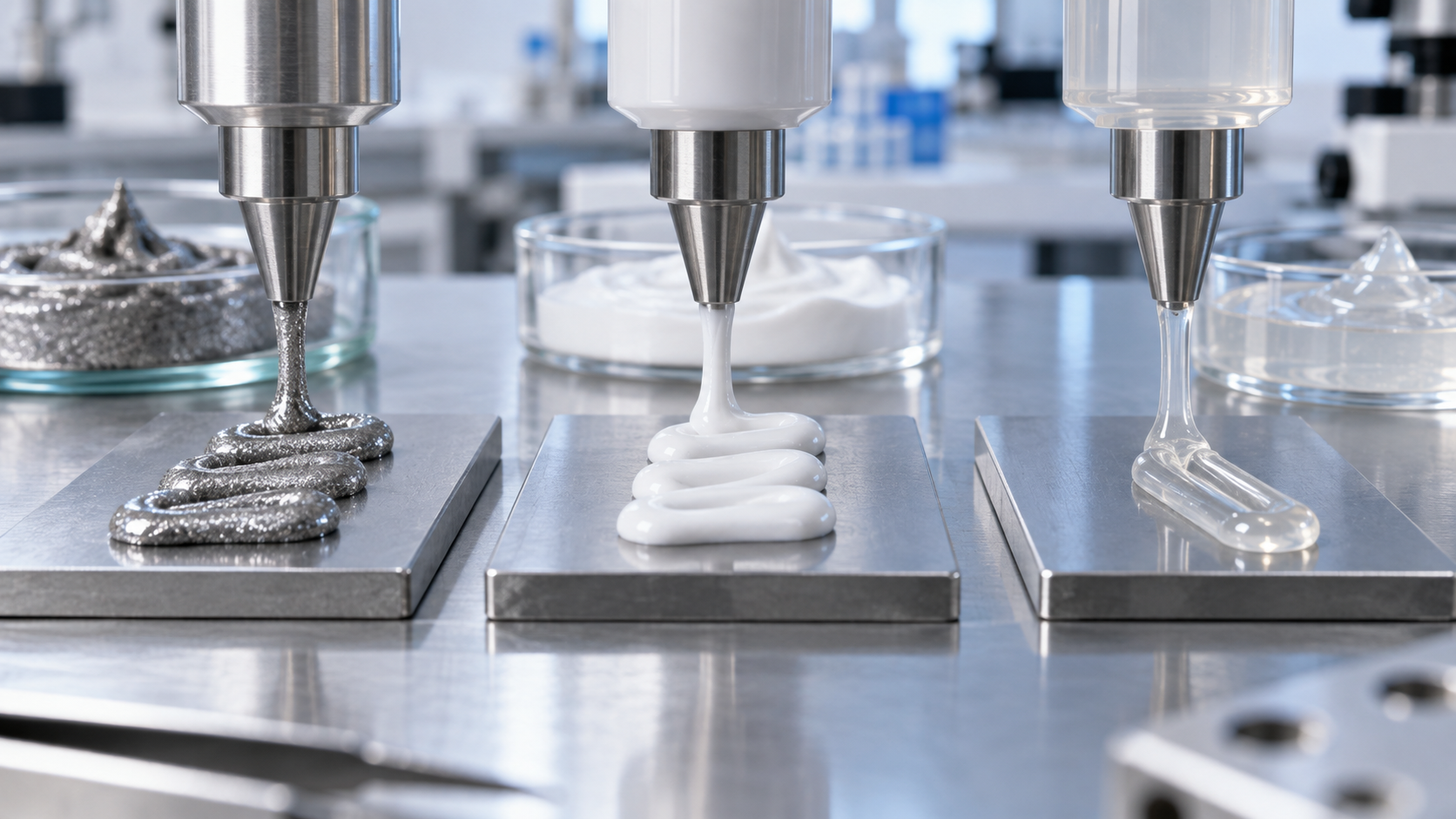
- What paste is, in three lines
- Make-up: particles and the liquid that carries them (the vehicle)
- Viscosity and thixotropy: read numbers together with the test conditions
- A materials engineer's view (1): one print stroke contains three time scales
- Printing and dispensing: stencil, screen, syringe
- Conductive pastes (silver and copper)
- A materials engineer's view (2): conduction is set by a network of particle contacts
- Solder paste: powder and flux
- A materials engineer's view (3): the price of finer powder is surface area and shelf life
- Reflow: drawing the temperature profile
- Insulating and sintering pastes
- Storage, thawing and shelf life
- How pastes are evaluated
- What is still hard, and what we could not confirm
- Glossary / References / Claim-to-source audit
Sourced = a statement in published material (link given)
Our calculation = a figure this article derived, with the assumptions spelled out
Not yet confirmed = a plan or target with no confirmed track record
Structural readings and materials-design interpretations are marked separately as Commentary.
Data-sheet values are the manufacturer's stated values; values for different grades, test conditions and revision dates are not lined up to rank one product above another.
1. What paste is, in three lines
A paste is a creamy material in which “particles” are dispersed in a “vehicle” (a carrier liquid) (this article's framing). In electronics assembly it is used to place particles with a function, such as conduction, joining or insulation, onto a board in a form that can be applied.
- Four kinds: we organise them as conductive pastes using silver or copper, solder pastes using solder-alloy powder, sintering pastes in which fine particles are joined by heat, and insulating pastes that do not conduct (this article's grouping)
- A shared challenge: the paste must flow when it passes through a nozzle or a stencil, hold its shape on the board, and then set by drying, curing, melting or sintering to deliver its function. Viscosity, thixotropy, printability and shelf life are design items common to all kinds
- Scope of this article: kinds, viscosity and thixotropy, printing, reflow, storage and evaluation. Using paste to bond chips is covered in our explainer on die attach
The performance of a paste is not decided by the particle material alone. Even with the same silver or the same solder alloy, the design of the vehicle and the size and shape of the particles change how fine a print can be, how long the paste keeps, and the resistance and reliability once it has set (this article's reading). When you read a number, always check under what conditions it was measured.
For the basics of resin curing see our explainer on epoxy resins; for fillers and interfaces see polymer blends and fillers; for sealing under a chip see underfill; for thermal expansion see the coefficient of thermal expansion.
2. Make-up: particles and the liquid that carries them (the vehicle)
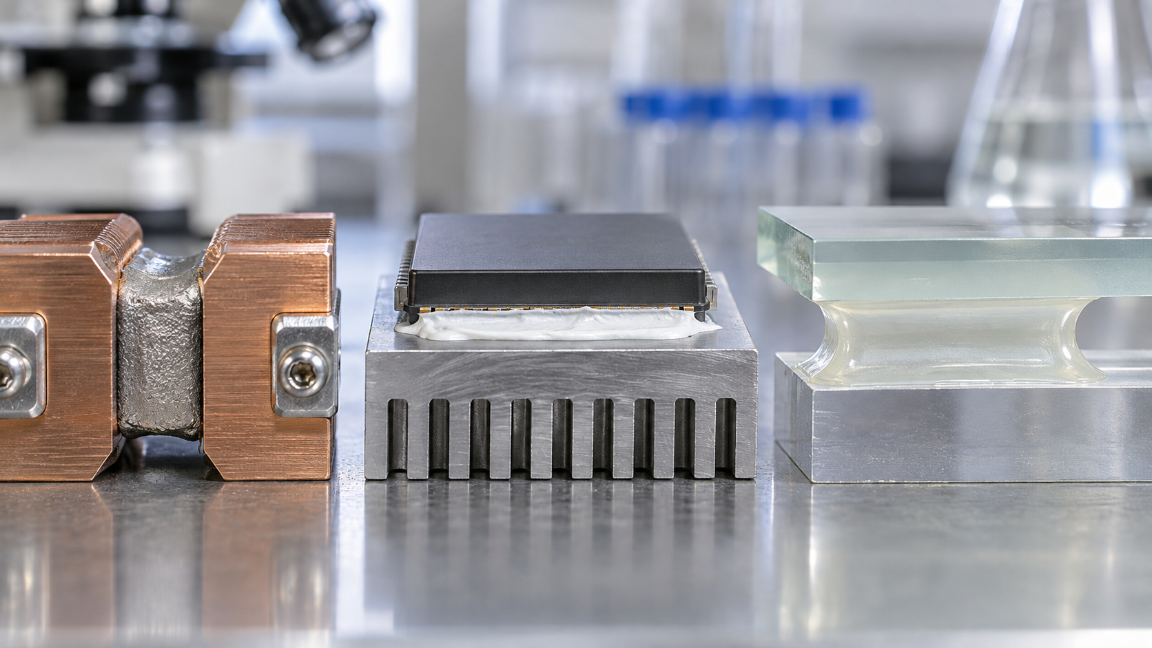
| Kind | Particles (carriers of the function) | Vehicle | How it sets | Published examples used in this article |
|---|---|---|---|---|
| Conductive paste | Silver (flakes), copper | Resin (thermoplastic or thermosetting) and solvent | Drying, or heat curing | Henkel LOCTITE ECI 1010 (drying type) and ABLESTIK 2815A (heat-curing type) [Ref. 9, 10] |
| Solder paste | Spherical solder-alloy powder (e.g. SAC305) | Flux (resin, activator, solvent, thixotropic agent) | Powder melts and coalesces in reflow | Indium10.1; IPC and JIS standards [Ref. 1-5] |
| Sintering paste | Fine particles of silver or copper, or copper plus tin alloy | Organic components (resin and so on) | Particles join each other on heating (sintering) | Resonac sintered copper paste; HT-610S [Ref. 13, 14] |
| Insulating paste | None (resin-based) in some examples | Acrylate resin and similar | UV curing | Henkel LOCTITE EDAG PF 455B [Ref. 11] |
A summary based on each company's published material. The grouping is this article's own, not an established industry classification. Sourced (the make-up as stated in the sources)
For solder paste, a Henkel patent (US9511453B2) explains that a flux generally consists of a resin, a thixotropic agent, an activator and a solventSourced [Ref. 8]. The same patent also says that the activator can interact with the alloy powder during storage, affecting the rheology (flow behaviour) and other properties, and can significantly reduce storage stability [Ref. 8]. This article does not interpret the scope of the patent's claims.
3. Viscosity and thixotropy: read numbers together with the test conditions
A paste has different viscosity when it is still and when it is being moved (our commentary). The property that viscosity falls as shear (deformation like rubbing layers past each other) gets faster is called shear thinning, and the property that viscosity slowly returns after movement stops is called thixotropy. A paste's viscosity number cannot be compared unless you know at what shear rate (or rotation speed) and on what instrument it was measured.
| Product (manufacturer's stated) | Kind | Viscosity | Test condition (as written in the data sheet) | Thixotropic index | Source |
|---|---|---|---|---|---|
| LOCTITE ECI 1010 (April 2025 edition) | Silver conductive ink (drying type) | 6,400 mPa·s | Rheometer, 25 °C, shear rate 1.5 1/s | 1.6 (15 / 1.5 1/s) | [Ref. 9] |
| LOCTITE ABLESTIK 2815A (April 2014 edition) | Silver die-attach paste (heat-curing type) | 8,000 mPa·s | Brookfield CP51, 25 °C, 5 rpm | 5.6 (0.5 / 5 rpm) | [Ref. 10] |
| LOCTITE EDAG PF 455B (November 2025 edition) | UV-curing insulating paste | 14,000 mPa·s | Brookfield #6SP, 25 °C, 20 rpm | Not stated | [Ref. 11] |
| Indium10.1 | Solder paste (SAC305, Type 4.5) | 1,450 poise | The test condition for viscosity could not be confirmed from the data sheet | Not stated | [Ref. 5] |
All Sourced (manufacturers' typical values; each data sheet says it is reference information, not a product specification). Instruments and conditions differ, so no ranking can be drawn from the size of the numbers.
Let us reinterpret a few of the numbers through conversion and estimationOur calculation.
- Poise to mPa·s: 1 poise = 0.1 Pa·s. Indium10.1's 1,450 poise = 145 Pa·s = 145,000 mPa·s (one to two orders of magnitude above the three products above, but the test condition is unknown, so we do not compare)
- Low-speed viscosity from the thixotropic index: if ABLESTIK 2815A's “thixotropic index (0.5 / 5 rpm) 5.6” is taken as the ratio of viscosities at 0.5 rpm and 5 rpm, the viscosity at 0.5 rpm is 5.6 × 8,000 = about 44,800 mPa·s (about 5.6 times the 5 rpm value)
- A rough shear rate near the squeegee: treating shear rate as speed divided by gap, the print speed of 50 to 100 mm/s [Ref. 5] divided by a stencil thickness of 0.127 mm [Ref. 4] gives about 390 to 790 1/s
Assumptions and limits: the definition of the thixotropic index (which viscosity is the numerator) is not given in the data sheet, so we assumed the common usage of “lower speed divided by higher speed”. For ECI 1010's “15 / 1.5 1/s” the order is reversed and the definition could not be confirmed, so we did not convert it. The shear rate near the squeegee is a rough estimate to get the order of magnitude, treating the gap as the stencil thickness; it is not a measured value.
Standards also treat viscosity as an item in its own right. IPC J-STD-005B (requirements for solder pastes, March 2024 edition) specifies test items including viscosity, slump, solder ball, tack and wettingSourced [Ref. 1]. Japan's JIS Z 3284-3:2024 (Solder paste - Part 3: Test methods for printability, viscosity, slump and tackiness) was made by modifying IEC 61189-5-3:2015 and specifies the printability test, viscosity test, slump-in-printing test, slump-in-heating test and tackiness testSourced [Ref. 2]. In its own scope, the IPC standard says it is a material quality-control document and is not intended to relate directly to the material's performance in the assembly process [Ref. 1].
4. A materials engineer's view (1): one print stroke contains three time scales
If we break one stencil-printing stroke into pieces, the paste faces three demands on different time scales (our commentary).
- Slow (seconds to hours): stay put. It must not slump, whether it sits on the stencil or has been printed on the board. This relies on high viscosity at low shear (a yield stress). The IPC J-STD-005 slump test checks it with a “cold slump” at 25 °C and a “hot slump” at 180 °CSourced [Ref. 4].
- An instant (milliseconds to seconds): flow. Pushed by the squeegee, it must enter the aperture. Here viscosity has to fall under high shear.
- Right after (seconds): recover. Just after the stencil is lifted, the deposit must stand in the shape of the aperture. This is where thixotropy (the speed of viscosity recovery) comes in.
The single viscosity figure in a data sheet is only one point out of these three. As the table above shows, the number for the same paste differs several-fold depending on whether the shear rate is 1.5 1/s or hundreds of 1/s. A viscosity number alone cannot tell you that a paste is “easy to print”; that is the basic fact to hold when handling pastes.
5. Printing and dispensing: stencil, screen, syringe
(1) Stencil printing (solder paste)
Solder paste is pushed with a squeegee through holes (apertures) cut in a thin metal plate (the stencil) and deposited on the pads of the boardSourced [Ref. 5].
The Indium Corporation data sheet (Indium10.1) lists the following recommended printing conditionsSourced (manufacturer's stated, reference values) [Ref. 5].
| Item | Value |
|---|---|
| Stencil | Electroformed, or laser-cut and electropolished, stencils give the best printing characteristics |
| Paste bead size | About 20 to 25 mm in diameter |
| Print speed | 50 to 100 mm/s |
| Squeegee pressure | 0.018 to 0.027 kg per mm of blade length |
| Separation speed | 5 to 20 mm/s (or the equipment maker's specification) |
| Underside stencil wipe | Start at once every 5 prints and reduce the frequency until the optimum is found |
| Stencil life | 18 hours (30 to 60% RH, 22 to 28 °C) |
| Aperture design | Reduce aperture area by 10 to 20% for discrete parts. For parts with 20 mil (about 0.5 mm) pitch or finer, a reduction of 5 to 15% is common |
Indium10.1 data sheet [Ref. 5]. Sourced (manufacturer's stated).
(2) Aperture size and powder size
According to the paper by Lentz (FCT Assembly), IPC-7525 (stencil design guidelines) takes an aspect ratio above 1.5 and an area ratio above 0.66 as the guide for good printingSourced [Ref. 4]. The area ratio is “aperture area divided by aperture wall area”, and it gets smaller for smaller apertures and thicker stencils. The paper also says it is common practice to use Type 4 or 5 powders for stencil designs whose area ratios fall below 0.66 [Ref. 4].
Area ratio: for a square aperture of side a and stencil thickness T, the area is a² and the wall area is 4aT, so area ratio = a / 4TOur calculation. For the paper's test patterns (aperture 0.254 mm = 10 mil, stencil 0.127 mm = 5 mil), 0.254 / (4 × 0.127) = 0.50, which agrees with the area ratio the paper gives [Ref. 4]. To exceed an area ratio of 0.66 with the same aperture, T ≤ 0.254 / (4 × 0.66) = about 0.096 mm is needed.
Minimum aperture guide: using IPC-7525's “five-ball rule” (the aperture side should be at least five times the largest particle size), the paper gives the minimum aperture for each powder type as 9 mil for Type 3, 7.5 mil for Type 4, 5 mil for Type 5 and 3 mil for Type 6 [Ref. 4]. Multiplying the upper ends of the main size ranges (45, 38, 25, 15 µm) by five gives 225, 190, 125 and 75 µm (8.9, 7.5, 4.9 and 3.0 mil), which nearly matches the paperOur calculation.
Assumptions and limits: the area-ratio formula assumes a square aperture; round or rectangular apertures change the coefficient. The five-ball rule is only the minimum condition for powder to pass through without clogging and does not guarantee print quality.
The paper says Type 3 is used for parts down to 0402 (imperial), Type 4 for 0201 and fine-pitch BGAs, Type 5 for parts such as 01005, and Types 5 and 6 also for dispensing such as jet printing [Ref. 4]. In the paper's tests (apertures with area ratios of 0.30 to 0.50, stencil thickness 127 µm), transfer efficiency (the share of the aperture's paste that moved to the board) was in the range of about 5 to 60%, generally higher with finer powder, though with exceptions [Ref. 4].
(3) Screen printing (conductive and insulating pastes)
Conductive inks and insulating pastes are printed through a mesh screen. The ECI 1010 data sheet recommends a polyester screen (68 to 90 mesh/cm), an emulsion thickness of 10 to 40 µm and a squeegee hardness of 70 to 80 [Ref. 9]. The PF 455B data sheet says the screen mesh sets the dry film thickness: 25 µm at 61 threads/cm, 18 µm at 77 threads/cm and 10 µm at 120 threads/cm [Ref. 11].
(4) Syringe dispensing (adhesive pastes)
ABLESTIK 2815A is a silver adhesive paste applied by dispenser. Its data sheet recommends a wet bondline of 25 to 50 µm and an amount that produces 25 to 50% filleting around the die, and notes that star or cross dispense patterns give fewer bondline voids than a matrix patternSourced [Ref. 10]. It also says that if the paste is left at room temperature beyond its work life (24 hours at 25 °C), silver and resin may separate [Ref. 10].
6. Conductive pastes (silver and copper)
A conductive paste is a paste in which metal particles (such as silver flakes) are dispersed in a resin binder. It is easiest to read them as two groups, according to how they set (this article's grouping).
| Item (manufacturer's stated) | LOCTITE ECI 1010 (April 2025) | LOCTITE ABLESTIK 2815A (April 2014) |
|---|---|---|
| Role | Conductive ink. Flexible circuits, RFID and other conductive circuits. Screen printing | Die-attach adhesive paste. Applied by dispenser |
| Resin type | Thermoplastic (set by heat “drying”) | Acrylate (set by heat “curing”) |
| How it is set | 15 minutes at 120 °C (forced air or infrared) | 30-minute ramp to 200 °C plus 30 minutes at 200 °C |
| Solids / filler | Solids 62 wt%, density 2.1 g/mL. Silver filler | Silver filler |
| Electrical properties | Sheet resistance 0.0057 Ω/sq (per 25 µm; 15 min at 120 °C). Resistance increase of 14% after a double crease test | Volume resistivity 0.00004 Ω·cm |
| Other properties | Operating temperature up to 100 °C. Substrates: PET, PI, PEN, paper | Thermal conductivity 20 W/(m·K), glass transition 63 °C (TMA), die shear strength 5.8 kgf at 25 °C (2 × 2 mm Si die) |
| Storage | 365 days from manufacture at 2 to 8 °C | 365 days from manufacture at −40 °C. Work life 24 hours at 25 °C |
Henkel data sheets [Ref. 9, 10]. Sourced (manufacturer's typical values). The 2815A data sheet is from 2014 and may not reflect the current product. Because test conditions differ, the two cannot be ranked.
Let us convert ECI 1010's “sheet resistance 0.0057 Ω/sq per 25 µm” to volume resistivityOur calculation. Volume resistivity = sheet resistance × thickness = 0.0057 Ω × 25 µm = 0.0057 × 25×10⁻⁴ cm = 1.4×10⁻⁵ Ω·cm = about 14 µΩ·cm. Put in the same unit, 2815A's volume resistivity of 0.00004 Ω·cm is 40 µΩ·cm.
For reference, the electrical resistivity of a sintered silver paste in a Resonac (formerly Hitachi Chemical) technical report is 2.0×10⁻⁸ Ω·m = 2.0 µΩ·cm (manufacturer's stated) [Ref. 13]. Conductive pastes containing resin therefore sit some several times to 20 times above this.
Assumptions and limits: ECI 1010's value is a conversion of a sheet resistance normalised to 25 µm film thickness; a different actual thickness changes the result. The three values are manufacturers' stated values for different products, set conditions and measurements, so they show only an order of magnitude, not a ranking.
Copper paste: an attempt to make conductors at low temperature
A Hitachi Chemical technical report (December 2015) describes the development of a low-temperature metallisation copper paste that can form wiring on resin film. As background it says that silver is the main conductive paste, but its use is limited to some devices because of the high price of the metal and concern about ion migration in fine wiring, and that replacement by cheaper and more reliable copper is expectedSourced [Ref. 12].
- Conditions and resistance: metallised at 140 °C for 1 hour in a nitrogen atmosphere under reduced pressure, giving a volume resistivity of 17 µΩ·cm and a screen-printed film thickness of 1 to 5 µm after metallisation [Ref. 12].
- Particle size: the copper particles are submicron, about 100 to 200 nm in diameter. The report shows in a figure that a film from small copper particles had a high volume resistivity of about 1000 µΩ·cm, while a film from larger particles had 17 µΩ·cm [Ref. 12].
- The stated reason: making particles smaller lowers their melting point, but the larger surface area makes them oxidise more easily and is thought to hinder metallisation, the report says [Ref. 12].
This report introduces a development product; whether it became a mass-production product, and its market status, could not be confirmed within the sources used hereNot yet confirmed.
7. A materials engineer's view (2): conduction is set by a network of particle contacts
The conductivity of a conductive paste is decided not by the resistance of the metal itself but by whether contacts between particles form a connected network (our commentary). Three observations in the published material support this view.
- Resistance is high when sintering does not advance: in Hitachi Chemical's copper paste, the film of small particles had about 1000 µΩ·cm and the film of larger particles 17 µΩ·cm, a difference of about 60 times (1000 / 17 = about 59)Our calculation. The report attributes this to particles failing to fuse and oxide films getting in the way of contact [Ref. 12].
- Bending reduces contacts: the ECI 1010 data sheet reports a 14% rise in resistance after a double crease test [Ref. 9]. This reads as bending slightly breaking the particle network (our interpretation).
- The binder changes how it sets: ECI 1010 simply “dries” a thermoplastic resin, while 2815A “cures” an acrylate. In a curing type, resin shrinkage presses particles together and strengthens contacts (our commentary; the same idea as in our explainer on ACF bonding).
What the material side can adjust is particle shape (flakes give larger contact areas), the combination of sizes, binder amount and shrinkage, and the temperature and atmosphere of setting. Replacing silver with copper adds a new problem: oxidation. Silver needs attention to ion migration, and Henkel explains that an insulating paste such as PF 455B is used for crossovers with a reduced risk of silver migration [Ref. 11]. The challenges of conductive pastes extend beyond conductivity to how they combine with the surrounding materials.
8. Solder paste: powder and flux
Solder paste is a paste made by mixing spherical solder-alloy powder with flux. IPC J-STD-005B states that solder powders are classified by particle shape and size distribution, that the flux properties of the paste shall be based on J-STD-004, and that the solder alloy properties shall be based on J-STD-006Sourced [Ref. 1].
Powder types (Type 3 to 6)
The classification that Lentz's paper reproduces from Table 3-2 of IPC J-STD-005A is as followsSourced [Ref. 4].
| IPC type | Range holding 80% or more | Up to 10% allowed on the large side | Less than 0.5% allowed above | Up to 10% allowed on the small side |
|---|---|---|---|---|
| Type 3 | 25 to 45 µm | 45 to 60 µm | Above 60 µm | Below 25 µm |
| Type 4 | 20 to 38 µm | 38 to 50 µm | Above 50 µm | Below 20 µm |
| Type 5 | 15 to 25 µm | 25 to 40 µm | Above 40 µm | Below 15 µm |
| Type 6 | 5 to 15 µm | 15 to 25 µm | Above 25 µm | Below 5 µm |
The standard itself is paid, so the table reproduced in the paper is shown (IPC J-STD-005A Table 3-2). J-STD-005B also has test clauses covering Type 7 and 8 powders [Ref. 1].
Alloy, metal content and flux classification
- Alloy: the Indium10.1 data sheet lists SAC305 (96.5Sn/3.0Ag/0.5Cu) and others as standard [Ref. 5]. AIM's alloy data sheet gives the melting temperature of SAC305 as solidus 217 °C and liquidus 220 °C [Ref. 16].
- Metal content (mass %): Indium10.1 is 88.75% for Type 3 and 88.5% for Type 4 / 4.5 (manufacturer's stated) [Ref. 5]. In Lentz's tests the content was lowered as powder got finer: 88.5% for Type 3, 88.3% for Type 4, 88.0% for Type 5 and 87.5% for Type 6 [Ref. 4].
- Flux classification: the Indium10.1 flux is ROL1 (a J-STD-004B classification) [Ref. 5]. In Lentz's paper the no-clean flux is ROL0 and the water-soluble flux is ORH1 [Ref. 4].
Let us convert a metal content of 88.5 wt% into a volume fractionOur calculation. Taking the specific gravity of SAC305 as about 7.38 [Ref. 15] and assuming the flux density is 1.0 to 1.1 g/cm³, metal volume = 88.5 / 7.38 = 12.0 and flux volume = 11.5 / (1.0 to 1.1) = 11.5 to 10.5, so the metal volume fraction is 12.0 / (12.0 + 11.5) = about 51% (about 53% if the flux is 1.1 g/cm³).
Assumptions and limits: the flux density of 1.0 to 1.1 g/cm³ is our assumption, not a published value. Gaps between powder particles and changes from solvent evaporation are ignored. The point is to get a feel for the order of magnitude: metal that is nearly 90% by weight is only about half by volume.
The role of flux, and the effect of finer powder
Lentz's paper explains that flux removes metal oxides and slows further oxidation. With finer powder, the surface area is larger for the same mass, so oxidation and reaction proceed more easilySourced [Ref. 4]. As consequences, the paper shows the following tendencies through tests and explanation [Ref. 4].
- The finer the powder, the more flux and metal react during storage to form salts, activity is used up, and the paste thickens and changes from a smooth, creamy look to a dull, grainy one.
- The drop in transfer efficiency between 8 and 24 hours on the stencil (the paper's “Drop in TE%”) was 8 for Type 3, 10 for Type 4, 18 for Type 5 and 25 for Type 6 in no-clean pastes, and 5, 5, 8 and 6 in water-soluble pastes.
- In the IPC slump test, hot slump (180 °C) was failed by the no-clean Type 6 and the water-soluble Types 5 and 6. In the IPC solder-ball test, all Type 6 pastes failed.
- With water-soluble flux, voiding tended to increase as the powder became finer.
The paper also cautions that these pastes were originally formulated for Type 3 and 4 powders and were not optimised for finer powders [Ref. 4]. So the results do not mean “fine powder is bad”; they show that the flux side must also be redesigned to suit the powder (our commentary).
9. A materials engineer's view (3): the price of finer powder is surface area and shelf life
The surface area per unit mass of a spherical powder is 6 / (density × diameter), inversely proportional to diameterOur calculation. Using a specific gravity of 7.38 for SAC305 [Ref. 15] and the midpoint of each main size range, the surface area per kilogram is as follows.
| Type | Midpoint diameter | Our calculation (sphere model) | Value in Lentz's paper | Ratio to Type 3 |
|---|---|---|---|---|
| Type 3 | 35 µm | 23.2 m² | 22.9 m² | 1.00 |
| Type 4 | 29 µm | 28.0 m² | 27.7 m² | 1.21 |
| Type 5 | 20 µm | 40.7 m² | 40.2 m² | 1.75 |
| Type 6 | 10 µm | 81.3 m² | 80.3 m² | 3.50 |
Example for Type 3: 6 / (7,380 kg/m³ × 35×10⁻⁶ m) = about 23.2 m²/kg. The difference from the paper's values [Ref. 4] is about 1 to 1.3%, so the simple assumptions of spheres and midpoint sizes nearly reproduce them.
Surface area is the “entrance” for oxidation, and also the amount the flux has “to deal with”. If an equal oxide thickness is assumed, the amount of oxide to be removed also scales roughly with surface area (our commentary; the oxide thickness is an assumption, not a published value). The paper explains that this is why finer powders show more random solder balling, graping (small particles that fail to coalesce and remain like a bunch of grapes) and reduced shelf life [Ref. 4].
This means printability (entering fine apertures) and shelf life and reflow behaviour (resisting oxidation) are in a trade-off through the same “particle size”. It has the same structure as the trade-off between “trapping” and “insulation” in our explainer on ACF bonding: improving one worsens the other. That is why the flux side needs stronger activity and better oxidation protection. For this shelf-life problem, Henkel presents a temperature-stable paste that can be stored at room temperature (LOCTITE GC 10) as a feature of its own product [Ref. 7].
10. Reflow: drawing the temperature profile
Printed solder paste is heated in a reflow oven after parts are placed. Solvent evaporates, flux removes oxide films, the powder melts and coalesces, and the joint cools and sets (this article's summary).
The recommended profile for SAC305 given in the Indium10.1 data sheet is as followsSourced (manufacturer's stated, reference values) [Ref. 5].
| Item | Recommended | Acceptable | Comment (as written in the data sheet) |
|---|---|---|---|
| Ramp (average, ambient to peak) | 1.0 to 1.5 °C/s | 0.5 to 2.5 °C/s | To minimise solder balling, beading and hot slump |
| Soak zone (optional) | 20 to 60 s at 140 to 160 °C | 30 to 120 s at 140 to 170 °C | May minimise BGA/CSP voiding. Eliminating or reducing the soak may help reduce HIP and graping |
| Time above liquidus (TAL) | 45 to 60 s | 30 to 100 s | Needed for good wetting and a reliable solder joint |
| Peak temperature | 230 to 260 °C | 230 to 262 °C | — |
| Cooling rate | 2 to 6 °C/s | 0.5 to 6 °C/s | Rapid cooling promotes a fine-grain structure |
| Atmosphere | Air or N2 | N2 preferred for small components | |
Indium10.1 data sheet [Ref. 5]. Sourced (manufacturer's stated). The data sheet says all values are for reference only and may need modification to fit the process. HIP is head-in-pillow (a defect where the solder on the part and the paste fail to coalesce; our note).
In Lentz's tests a different profile was used (ramp 1.7 to 1.8 °C/s, 61 to 67 s above 220 °C, peak 241 to 248 °C, 4.70 minutes from room temperature to peak) [Ref. 4]. Even for the same SAC305, the profile changes with the paste, part and board, and there is no single right answer.
11. Insulating and sintering pastes
Insulating paste: a material that must not conduct is also a paste
A typical use of an insulating paste is to insulate a crossover of wiring printed over a conductive paste. Henkel's LOCTITE EDAG PF 455B (data sheet of November 2025) is a UV-curing, acrylate-based insulating ink used by screen printingSourced [Ref. 11].
| Item (manufacturer's stated) | Value or statement |
|---|---|
| Uncured state | 100% solids, viscosity 14,000 mPa·s (Brookfield #6SP, 25 °C, 20 rpm), density 1.02 g/cm³ |
| Printing | Monofilament polyester screens (61 to 120 threads/cm). Dry film thickness 25 µm at 61 threads/cm, 18 µm at 77 and 10 µm at 120 |
| Making a crossover | A thickness of 25 to 30 µm is printed in two passes (12 to 15 µm each), giving a pore-free film. Each layer is cured with 0.5 J/cm² of UV. Inks printed over it must be dried within 5 minutes |
| After curing | Adhesion 5B, pencil hardness B, breakdown voltage above 2,700 V (AC) at 25 µm |
| Storage | 1 year at 5 to 25 °C (from the qualification date). Optimum 5 to 30 °C. Below 0 °C or above 40 °C can adversely affect properties. If it forms a gel after storage, warm it in a water bath at 65 °C or below and stir |
Henkel data sheet [Ref. 11]. Sourced (manufacturer's typical values).
Two calculations can be made from PF 455B's numbersOur calculation.
- Checking the coverage: with 100% solids and a density of 1.02 g/cm³, 1 kg occupies 1000 / 1.02 = 980 cm³. Spread to a dry thickness of 10 µm (= 10⁻³ cm), it covers 980 / 10⁻³ cm = 9.8×10⁵ cm² = 98 m², which agrees with the data sheet's “theoretical coverage 98 m²/kg”.
- A lower bound on dielectric strength: above 2,700 V at 25 µm means 2,700 / 25 = above 108 V/µm (= 108 kV/mm).
By the same approach, from the conductive ink ECI 1010's “theoretical coverage 10.6 m²/kg (10 µm dry film)” and “solids 62 wt%”, the average density of the dry film is 0.62 kg / (10.6 m² × 10 µm = 106 cm³) = about 5.9 g/cm³. If we assume a silver density of about 10.5 g/cm³ and a resin of 1.2 g/cm³ and split it into two components, silver is about 90% by mass and about half by volume.
Assumptions and limits: the last estimate is a rough two-component calculation. The silver density (a general value) and the resin density are our assumptions, not the formulation stated in the data sheet. Treat “about half by volume” only as a reference for thinking about how much material particles need to form a contact network.
Sintering paste: joining by “connecting grains of metal” instead of solder
For joining chips in power semiconductors and similar uses, joining materials to replace lead-free solder are being sought. A Hitachi Chemical technical report (December 2017) points out that because solder joins by using the melting point of the metal, the joint melts again, which makes secondary assembly difficult, makes bond position hard to control, and rules out use above the joining temperature [Ref. 13]. Two approaches are given as alternatives.
- TLPS (transient liquid phase sintering) paste: Hitachi Chemical's “HT series” disperses copper particles and tin-alloy particles in a thermoplastic (polyimide) resin. At the sintering temperature the tin alloy melts and reacts with the copper particles to form a copper-tin intermetallic compound with a high melting point, so it does not remelt even in secondary assembly (remelting temperature above 400 °C), the report says [Ref. 13].
- Sintered copper paste: Resonac proposes a sintered copper bonding paste with a thermal conductivity of 300 W/(m·K), equal to sintered silver, and with improved reliability. There is a die-bond type (intended for 5 to 13 mm square) and a large-area type for joining to coolers (intended for 30 to 50 mm square; a development product) [Ref. 14].
| Item (manufacturer's stated) | HT-610S | Pb-free solder SAC305 | Sintered silver paste |
|---|---|---|---|
| Application | Die bonding material | Mounting material | Die bonding material |
| Bonding condition | 260 °C, N2 reflow | 260 °C, N2 reflow | 250 °C, hot press |
| Remelting temperature | Above 400 °C | 220 °C | 960 °C |
| Coefficient of thermal expansion | 19 ppm/°C | 19 ppm/°C | 20 ppm/°C |
| Elastic modulus | 3.5 GPa | 31 GPa | 30 GPa |
| Electrical resistivity | 5.0×10⁻⁷ Ω·m | 1.1×10⁻⁷ Ω·m | 2.0×10⁻⁸ Ω·m |
| Thermal conductivity | 43 W/(m·K) | 55 W/(m·K) | 400 W/(m·K) |
| Reliability test (temperature cycling) | 3,000 cycles (−65 to 175 °C) | 2,000 cycles (−40 to 125 °C) | 3,000 cycles (−65 to 175 °C) |
| Self-alignment | None | Yes | None |
Table 1 of Hitachi Chemical Technical Report No. 60 (December 2017) [Ref. 13]. Sourced (manufacturer's stated). The temperature-cycling conditions differ by column (only SAC305 is −40 to 125 °C), so no conclusion about reliability can be drawn. For the details of these materials as bonding materials, see our explainer on die attach.
The Resonac sintered copper paste page says that in a power cycle test (Tj,max = 175 °C) the characteristic life was about 40 times that of high-lead solder and about 5 times that of sintered silver. The page adds that the data shown are “typical values given as examples of measurement or calculation results, not guaranteed values”Sourced (manufacturer's stated) [Ref. 14].
12. Storage, thawing and shelf life
A paste is a material that changes with time. Lentz's paper explains that during storage the flux reacts with the metal to form salts and its activity is used up, that this reaction is faster for finer powder, and that refrigeration slows its progress [Ref. 4]. The Henkel patent likewise says that the activator can be a factor that lowers storage stability [Ref. 8].
| Product (manufacturer's stated) | Storage and shelf life | Handling before use | Source |
|---|---|---|---|
| Indium10.1 (solder paste) | Unopened: 12 months in cold storage (below 10 °C) / 30 days maximum at room temperature (20 to 30 °C) | Take out of refrigeration at least 2 hours before use, check the temperature, then open. Record the opening date and time on the container. Store cartridges tip down | [Ref. 5] |
| Indium6.5R (water-soluble SnPb paste) | Preliminary shelf life of 6 months below 10 °C | Ideal working environment 23 to 28 °C and 25 to 50% RH. Out of refrigeration for 2 hours or more | [Ref. 6] |
| LOCTITE ABLESTIK 2815A (silver adhesive paste) | 365 days from manufacture at −40 °C. Work life 24 hours at 25 °C | Thaw with the syringe upright. Do not open until it reaches 25 °C. Wipe off condensation on the container before opening. Do not refreeze | [Ref. 10] |
| LOCTITE ECI 1010 (silver conductive ink) | 365 days from manufacture at 2 to 8 °C. Below 0 °C or above 30 °C adversely affects properties | Mix thoroughly before use. Do not return removed material to the original container | [Ref. 9] |
| LOCTITE EDAG PF 455B (insulating ink) | 1 year at 5 to 25 °C (from the qualification date). Optimum 5 to 30 °C | Stir slowly to avoid entraining air. If it forms a gel, warm to 65 °C or below and stir | [Ref. 11] |
Each company's data sheet. Sourced (manufacturer's stated; they depend on product and lot, so always check the latest data sheet).
Against these, Henkel positions LOCTITE GC 10 as a “temperature stable” solder paste and says it is formulated to be stable for one year at 26.5 °C and for one month at temperatures up to 40 °C. The company says the abandon time (how long paste can be left on the stencil) is typically 1 to 4 hours, while GC 10 allows up to 24 hours with zero start-up timeSourced (a company claim; a promotional white paper that includes customer testimonials) [Ref. 7]. This article has not confirmed that these figures were verified by a third party.
- Paste is “particles plus vehicle” and can be organised into four kinds: conductive, solder, sintering and insulating. Even though they set differently, viscosity, thixotropy, printability and shelf life are shared design itemsSourced
- A viscosity number must be read together with the shear rate and instrument. The shear rate near the squeegee is, in our estimate, about 390 to 790 1/sOur calculation
- Finer powder prints through smaller apertures (from about 225 µm for Type 3 to about 75 µm for Type 6), but surface area per unit mass rises by up to 3.5 times, which affects shelf life and reflow behaviourSourced
- The metal in solder paste is about 88.5% by weight but only about half by volumeOur calculation
- The resistance of a conductive paste is set by its network of particle contacts. A film of small copper particles that sintered poorly had about 60 times the volume resistivitySourced
- Storage is an operation to slow reactions. The data sheets describe cold or frozen storage and warming to room temperature before useSourced
13. How pastes are evaluated
Evaluation of a paste can be organised as inspection of the material itself (standard tests) and performance in the process (printing, reflow and properties after setting) (this article's grouping).
| Evaluation item | What is examined | Standard or method (examples) | Source |
|---|---|---|---|
| Alloy and flux | Alloy composition; flux characteristics and classification | Based on IPC J-STD-006 (alloy) and J-STD-004 (flux) | [Ref. 1] |
| Powder | Particle size and shape | IPC J-STD-005B (powder size and shape). JIS Z 3284-2 (test methods for solder particle shape, surface condition judgment and particle size distribution) | [Ref. 1, 2] |
| Metal content | Mass % of metal in the paste | IPC J-STD-005B | [Ref. 1] |
| Viscosity | Ease of flow | IPC J-STD-005: T-bar spindle and spiral pump methods. JIS Z 3284-3 | [Ref. 1, 2, 4] |
| Slump | Whether it keeps its shape | IPC J-STD-005: cold (25 °C) and hot (180 °C). JIS Z 3284-3 (slump in printing, slump in heating) | [Ref. 2, 4] |
| Solder ball | Whether unwanted small balls appear in reflow | IPC J-STD-005: frosted glass slide on a hot plate (245 to 250 °C). JIS Z 3284-4 | [Ref. 3, 4] |
| Tack | Force that holds the part | IPC J-STD-005. JIS Z 3284-3 (tackiness test). Lentz's tests also measured after holds of 24 to 72 hours using the JIS method | [Ref. 2, 4] |
| Wetting and spread | Whether molten solder spreads | IPC J-STD-005. JIS Z 3284-4 (test methods for wettability, solderball and spread) | [Ref. 3] |
| Print performance | Transfer efficiency; stencil life | Volume measured with a solder paste inspection system (SPI). Repeated print-and-pause (0, 1, 2, 4, 8, 24 hours) | [Ref. 4] |
| Performance after reflow | Wetting, random solder balling, graping, voids | Dedicated test board. Voids measured on QFN thermal pads | [Ref. 4] |
| Storage stability | Change after storage or heating | Heat ageing in sealed jars at 50 to 55 °C for 72 hours, followed by viscosity, solder ball and tack measurements | [Ref. 4] |
| Conductive pastes | Resistance, bending, bond strength | Sheet resistance, resistance rise after a double crease test, die shear strength (data-sheet items) | [Ref. 9, 10] |
| Insulating pastes | Adhesion, hardness, breakdown voltage | Cross-hatch adhesion 5B, pencil hardness, AC breakdown voltage at 25 µm (data-sheet items) | [Ref. 11] |
All Sourced (titles, scope and contents of standards, and statements in data sheets and papers). The standards themselves are paid, so the test conditions in their text were not checked; only what is written in papers and data sheets is given.
JIS Z 3284 is a series of four parts: Part 1, kinds and quality classification; Part 2, test methods for solder particle shape, surface condition judgment and particle size distribution; Part 3, test methods for printability, viscosity, slump and tackiness (revised in 2024); and Part 4, test methods for wettability, solderball and spreadSourced [Ref. 2]. Part 4 (established in 2014) specifies the wettability, solder-ball and spread tests [Ref. 3].
14. What is still hard, and what we could not confirm
(1) The definition of the thixotropic index, and viscosity at high shear
The definition (numerator and denominator) of the thixotropic indices such as ABLESTIK 2815A's “0.5 / 5 rpm” and ECI 1010's “15 / 1.5 1/s” is not written in the data sheets, so this article assumed the usual usage. Also, no measured viscosity at the high shear of printing could be found in published material, so the figure in chapter 3 draws the curve shape for illustration and the shear rate near the squeegee is only an estimate.
(2) The test condition for Indium10.1's viscosity
For Indium10.1's “1,450 poise”, the instrument, rotation speed and temperature could not be confirmed from the data sheet used here. We therefore make no comparison with other companies' products.
(3) How far the standards were checked
For IPC J-STD-005B and JIS Z 3284, we checked only titles, scope and tables of contents; the detailed limits of the powder classes and the precise conditions of each test are shown only as written in the paper (Lentz) and data sheets. The title and contents of J-STD-004 (flux) are touched on only as cited by J-STD-005B and were not confirmed here.
(4) Flux formulation ratios and sintering-paste details
Flux components are limited to the description in the patent (resin, thixotropic agent, activator, solvent); formulation ratios and specific compounds could not be confirmed in the companies' data sheets. The bonding conditions (pressure, time), particle sizes and organic components of sintering pastes could also not be confirmed in the public sources used, so they are not stated.
(5) Mass-production status of copper paste
Hitachi Chemical's low-temperature metallisation copper paste is a report on a development product from 2015. Its present commercial or mass-production status could not be confirmed within this surveyNot yet confirmed.
(6) The paper's tests are results from pastes made for the study
Lentz's paper compared water-soluble and no-clean SAC305 pastes made for testing (the year of publication is not stated in the PDF we checked; its references run to 2017), so the results do not apply to every commercial product.
(7) What is not covered
Legal regulation of lead-free soldering, electrode pastes for solar cells, thick-film pastes (for ceramic substrates), and market size and share (market-research estimates) are not covered in this article.
15. Glossary
- Paste
- A creamy material with particles dispersed in a liquid. In this article, organised into conductive, solder, sintering and insulating kinds.
- Vehicle
- The liquid part that carries the particles: resin, solvent, flux and so on.
- Flux
- A component that removes oxide films from metal surfaces in soldering and prevents re-oxidation. Made of resin, activator, solvent and thixotropic agent.
- Shear rate
- How fast a material is being rubbed past itself. Unit 1/s. The larger it is, the harder the material is being worked.
- Shear thinning
- The property that viscosity falls as shear rate rises.
- Thixotropy
- The property that viscosity drops when worked and slowly recovers when left still.
- Thixotropic index
- A ratio of viscosities measured at different speeds, used as a measure of thixotropy. The definition follows each product's notation.
- Slump
- The phenomenon of printed paste spreading after it is placed, and the test for it.
- Tack
- The stickiness of the paste; the force that holds a part once placed.
- Solder ball
- Unwanted small solder balls left around the joint after reflow.
- Graping
- A defect in which small solder particles fail to coalesce and remain like a bunch of grapes.
- Transfer efficiency
- The share of the aperture's volume that actually moves to the board.
- Area ratio
- Aperture area divided by aperture wall area. The smaller it is, the harder the paste releases.
- Stencil / squeegee
- A thin metal plate with apertures / the blade that pushes paste into them.
- Reflow
- The step of melting printed solder paste in a heating oven to make the joint.
- Liquidus (TAL)
- The temperature at which an alloy is completely molten. Time above liquidus is TAL.
- No-clean / water-soluble
- A flux that need not be cleaned off / a flux washed off with water.
- Sintering
- Joining particles by heat without fully melting them.
- TLPS
- Transient liquid phase sintering. A metal that is liquid for a time reacts with particles to make a high-melting compound.
- Ion migration
- Metal moving as ions under voltage and bridging electrodes. A particular concern with silver.
- Sheet resistance
- Film resistance expressed per square (Ω/sq). Multiplied by thickness it gives volume resistivity.
16. References
- IPC IPC-J-STD-005B "Requirements for Solder Pastes" (March 2024): PDF with the table of contents and scope — ipc.org
- Japanese Standards Association (JSA) JIS Z 3284-3:2024 "Solder paste - Part 3: Test methods for printability, viscosity, slump and tackiness" (preview of the standard, English) — webdesk.jsa.or.jp
- Japanese Standards Association (JSA) JIS Z 3284-4:2014 "Solder paste - Part 4: Test methods for wettability, solderball and spread" (preview of the standard, in Japanese; the English title is as listed in Ref. 2) — webdesk.jsa.or.jp
- Tony Lentz (FCT Assembly) "Size Matters - The Effects of Solder Powder Size on Solder Paste Performance", SMTA conference paper (the PDF gives no publication year; its references run to 2017) — smtnet.com
- Indium Corporation Indium10.1 Pb-Free Solder Paste, Product Data Sheet, Form No. 98881 R7 (©2022) — indium.com
- Indium Corporation Indium6.5R Water-Soluble SnPb Solder Paste, Product Data Sheet, Form No. 100151 (A4) R2 (©2025) — indium.com
- Henkel Mark Currie, "Temperature Stable Solder Paste Transforming Industry Mindset" (white paper on LOCTITE GC 10; includes company claims) — dm.henkel-dam.com
- Henkel AG & Co. KGaA (applicant) Patent US9511453B2 "Solder paste composition, a solder paste and a soldering flux" (published 6 December 2016) — patents.google.com
- Henkel Technical Data Sheet LOCTITE ECI 1010, April 2025 — datasheets.tdx.henkel.com
- Henkel Technical Data Sheet LOCTITE ABLESTIK 2815A, April 2014 — datasheets.tdx.henkel.com
- Henkel Technical Data Sheet LOCTITE EDAG PF 455B, November 2025 — datasheets.tdx.henkel.com
- Kosuke Urashima (Hitachi Chemical) "Cu Paste for Low Temperature Metallization Process", Hitachi Chemical Technical Report No. 58, pp. 30-31, December 2015 (bilingual PDF hosted by Resonac) — resonac.com
- Masaki Takeuchi and Fumitaka Ueno (Hitachi Chemical) "Transient Liquid Phase Sintering Paste, HT Series", Hitachi Chemical Technical Report No. 60, pp. 33-34, December 2017 (bilingual PDF hosted by Resonac) — resonac.com
- Resonac Sintered copper bonding paste with reliability exceeding sintered silver and a thermal conductivity of 300 W/(m·K) (Japanese-language page; updated 13 December 2023) — resonac.com
- AIM Solder Technical Data Sheet, SAC305 (Sn/Ag3.0/Cu0.5) bar solder (specific gravity about 7.38; melting temperature 217 to 218 °C), as hosted by RS Components — assets.rs-online.com
- AIM Solder Technical Data Sheet, SAC305 Lead-Free Solder Alloy (solidus 217 °C, liquidus 220 °C), as hosted by TestEquity — assets.testequity.com
17. Claim-to-source audit
| Claim in the text | Basis | Label |
|---|---|---|
| The scope of IPC J-STD-005B (March 2024): general requirements for characterising and testing solder pastes; a material quality-control document not intended to relate directly to performance in the assembly process. That powders are classified by shape and size distribution, that flux follows J-STD-004 and alloy follows J-STD-006. The test items for viscosity, slump, solder ball, tack and wetting. That there are clauses for Type 1 to 6 and for Type 7 and 8 powders | Reference 1 https://www.ipc.org/TOC/IPC-J-STD-005B-TOC.pdf | Sourced |
| The title of JIS Z 3284-3:2024, that it is a modified standard based on IEC 61189-5-3:2015, and that it specifies the printability, viscosity, slump-in-printing, slump-in-heating and tackiness tests. The titles of the four parts of the JIS Z 3284 series | Reference 2 https://webdesk.jsa.or.jp/preview/pre_jis_z_03284_003_000_2024_e_ed10_ch.pdf | Sourced |
| The title and establishment of JIS Z 3284-4:2014 (wettability, solder ball and spread tests) | Reference 3 https://webdesk.jsa.or.jp/preview/pre_jis_z_03284_004_000_2014_j_ed10_ch.pdf | Sourced |
| The Type 3 to 6 powder size table (reproduced from IPC J-STD-005A Table 3-2). The surface-area table (22.9, 27.7, 40.2 and 80.3 m² per kg), the five-ball-rule minimum apertures (9, 7.5, 5 and 3 mil), the IPC-7525 guide (aspect ratio above 1.5, area ratio above 0.66), and the uses of each type. The metal contents tested (88.5, 88.3, 88.0 and 87.5%), ROL0 and ORH1 fluxes, transfer efficiency of 5 to 60%, the slump (25 °C and 180 °C) and solder-ball results, the drop in transfer efficiency from 8 to 24 hours, increased voiding with water-soluble flux, the storage and heat-ageing results, that flux removes oxides, and the test methods | Reference 4 https://www.smtnet.com/library/files/upload/Effects-of-solder-powder-size-on-paste.pdf | Sourced |
| Indium10.1 data sheet: viscosity 1,450 poise (SAC305 Type 4.5), flux classification ROL1, metal content (88.75% for Type 3, 88.5% for Type 4 / 4.5), storage (12 months cold, 30 days at room temperature, thaw of 2 hours or more), printing conditions (bead size, speed, pressure, separation speed, underside wipe, 18-hour stencil life), aperture design, and the SAC305 reflow profile (ramp, soak, TAL, peak, cooling, atmosphere) | Reference 5 https://www.indium.com/wp-content/uploads/2025/03/Indium10.1-Pb-Free-Solder-Paste-PDS-98881-R7-1.pdf | Sourced |
| Indium6.5R: a preliminary shelf life of 6 months below 10 °C, a working environment of 23 to 28 °C and 25 to 50% RH, and a thaw of 2 hours or more | Reference 6 https://www.indium.com/wp-content/uploads/2025/01/Indium6.5R-Water-Soluble-SnPb-Solder-Paste-PDS-100151-A4-R2.pdf | Sourced |
| LOCTITE GC 10: stability for one year at 26.5 °C and one month up to 40 °C; abandon time typically 1 to 4 hours versus up to 24 hours; zero start-up time (company claims; a white paper with customer testimonials) | Reference 7 https://dm.henkel-dam.com/is/content/henkel/whitepaper-loctite-gc10-temperature-stable-solder-paste | Sourced |
| That a flux generally consists of resin, thixotropic agent, activator and solvent. That an activator can interact with alloy powder during storage and affect rheology and other properties, reducing storage stability | Reference 8 https://patents.google.com/patent/US9511453B2/en | Sourced |
| LOCTITE ECI 1010 values (solids 62 wt%, density 2.1 g/mL, viscosity 6,400 mPa·s at 1.5 1/s, thixotropic index 1.6, theoretical coverage 10.6 m²/kg, sheet resistance 0.0057 Ω/sq at 25 µm, 14% resistance rise after crease test, drying 15 min at 120 °C, operating temperature up to 100 °C, screen conditions, storage 365 days at 2 to 8 °C) | Reference 9 https://datasheets.tdx.henkel.com/LOCTITE-ECI-1010-EC-en_GL.pdf | Sourced |
| LOCTITE ABLESTIK 2815A values (thixotropic index 5.6, viscosity 8,000 mPa·s at 5 rpm, work life 24 hours, 365 days at −40 °C, cure conditions, thermal conductivity 20 W/(m·K), volume resistivity 0.00004 Ω·cm, glass transition 63 °C, die shear strength, dispense amount and pattern, thaw procedure, silver-resin separation) | Reference 10 https://datasheets.tdx.henkel.com/LOCTITE-ABLESTIK-2815A-en_GL.pdf | Sourced |
| LOCTITE EDAG PF 455B values (acrylate, UV curing, 100% solids, viscosity 14,000 mPa·s, density 1.02 g/cm³, theoretical coverage 98 m²/kg, screens and film thickness, two passes and 0.5 J/cm², breakdown voltage above 2,700 V, adhesion 5B, pencil hardness B, storage 1 year at 5 to 25 °C) and that it is used for crossovers with a reduced risk of silver migration | Reference 11 https://datasheets.tdx.henkel.com/LOCTITE-EDAG-PF-455B-EC-en_GL.pdf | Sourced |
| Low-temperature copper paste: that silver is the main conductive paste and its use is limited by metal price and ion-migration concerns; volume resistivity of 17 µΩ·cm after 1 hour at 140 °C in nitrogen under reduced pressure; film thickness of 1 to 5 µm; particle diameter of 100 to 200 nm; about 1000 µΩ·cm for the small-particle film; the statements on oxidation and surface area | Reference 12 https://www.resonac.com/sites/default/files/2022-12/pdf-rd-report-058-58_tr09.pdf | Sourced |
| The TLPS "HT" series: composition (copper particles, tin-alloy particles, thermoplastic polyimide), remelting temperature above 400 °C, the comparison table for HT-610S, SAC305 and sintered silver paste (bonding condition, thermal expansion, modulus, resistivity, thermal conductivity, temperature cycling, self-alignment), and the report's summary of solder's limits | Reference 13 https://www.resonac.com/sites/default/files/2022-12/pdf-rd-report-060-60_tr09.pdf | Sourced |
| Sintered copper bonding paste: thermal conductivity 300 W/(m·K) versus 30 W/(m·K) for high-lead solder; characteristic life in the power cycle test (Tj,max = 175 °C); the die-bond type (5 to 13 mm square) and large-area type (30 to 50 mm square, development product); that the data are typical values, not guaranteed | Reference 14 https://www.resonac.com/jp/solution/sinteredcopperpaste.html | Sourced |
| The specific gravity of SAC305 (about 7.38) | Reference 15 https://assets.rs-online.com/v1698743570/Datasheets/ec84ed6151a113af47e2746fced2b352.pdf | Sourced |
| The solidus (217 °C) and liquidus (220 °C) of SAC305 | Reference 16 https://assets.testequity.com/te1/Documents/AIM_SAC305_TDS.pdf | Sourced |
| The mass-production status of the low-temperature copper paste (a development-product report; no confirmation of commercialisation) | Reference 12 https://www.resonac.com/sites/default/files/2022-12/pdf-rd-report-058-58_tr09.pdf | Not yet confirmed |
| The conversion 1 poise = 0.1 Pa·s (1,450 poise = 145,000 mPa·s). The estimate of about 44,800 mPa·s at 0.5 rpm from the thixotropic index of 5.6. The shear rate near the squeegee of about 390 to 790 1/s | Our calculation. The thixotropic index was assumed to be lower-speed over higher-speed. The shear rate is a rough estimate of print speed of 50 to 100 mm/s divided by a stencil thickness of 0.127 mm, not a measured value | Our calculation |
| Area ratio = side / (4 × stencil thickness), the 0.50 example, and the stencil thickness of about 0.096 mm needed for an area ratio above 0.66. The five-ball-rule aperture guides (225, 190, 125 and 75 µm) | Our calculation. A square aperture was assumed. The five-ball rule was taken as five times the upper end of the main size range | Our calculation |
| Converting 0.0057 Ω/sq at 25 µm to about 14 µΩ·cm, 2815A at 40 µΩ·cm, and about 60 times (1000 / 17) for the copper-paste films. The average dry-film density of ECI 1010 of about 5.9 g/cm³ and the estimate of silver at about 90% by mass and about half by volume | Our calculation. The last estimate rests on our assumptions of about 10.5 g/cm³ for silver and 1.2 g/cm³ for resin. No ranking is implied because set conditions and measurement methods differ by product | Our calculation |
| Converting a metal content of 88.5 wt% to about 51 to 53 vol% | Our calculation. Based on a specific gravity of 7.38 for SAC305 (Reference 15) and our assumed flux density of 1.0 to 1.1 g/cm³ | Our calculation |
| Surface area per kilogram from the sphere model (23.2, 28.0, 40.7 and 81.3 m²) and the difference of about 1 to 1.3% from the paper's values | Our calculation. 6 / (density × diameter), with a density of 7.38 g/cm³ and midpoint diameters of 35, 29, 20 and 10 µm | Our calculation |
| Drawing the reflow curve (ramp 1.25 °C/s, soak at 150 °C for 40 s, about 48 s above liquidus, peak 245 °C, cooling 3 °C/s, about 309 s in total) | Our calculation and drawing. An example drawn by us inside the ranges of Reference 5; not a record from a real oven | Our calculation |
| Checking PF 455B's coverage (98 m²/kg) and a dielectric strength above 108 V/µm | Our calculation, derived from the data-sheet values of 100% solids, 1.02 g/cm³, 25 µm and 2,700 V | Our calculation |
| The definition of the thixotropic index, the test condition for Indium10.1's viscosity, viscosity at high shear, flux formulation ratios, bonding conditions of sintering pastes, and detailed test conditions in the text of the standards | Not confirmed in the public sources used, so not stated (our note) | Commentary |
| The framing of paste as “particles plus vehicle” and its grouping into conductive, solder, sintering and insulating kinds; the three time scales of printing (stay, flow, recover); that conduction is set by a network of particle contacts; that finer powder is a trade-off between printability and shelf life; and that the flux must be redesigned to suit the powder | Commentary: this article's own organisation and interpretation of the published content; not views stated by the companies or institutions | Commentary |
| That the hero image and Fig. 1 are AI-generated images and that Figs. 2 to 7 are explanatory drawings | Our own note in this article | Commentary |
Last updated: 3 October 2026. Sources are limited to primary material (official pages of standards bodies, manufacturers' official data sheets and technical reports, and papers). Because this article includes structural readings and materials-design interpretations, these are labelled “Commentary” and kept separate from sourced facts. Data-sheet values are the manufacturer's stated values; values for different grades and test conditions are not lined up to rank products. The definition of the thixotropic index, the test condition for Indium10.1's viscosity, viscosity at high shear, flux formulation ratios, bonding conditions of sintering pastes, the mass-production status of copper paste, and the detailed test conditions in the text of the standards could not be confirmed in published primary sources and are therefore not stated. Fig. 1 and the hero image are AI-generated images; Figs. 2 to 7 are vector drawings (Figs. 3 to 6 include our calculations), and none of them shows an actual micrograph or real product.