TECHNOLOGY EXPLAINER
Thermally Conductive Pastes and Gap Fillers
— Reading “W/(m·K)” together with how it was measured
Between a heat-generating part and its heat sink there is an invisible gap, and air conducts heat very poorly. What fills that gap is a paste (grease) or a liquid gap filler: a resin packed with thermally conductive filler. This article covers the make-up of filler and resin, thermal conductivity and interface resistance, the standards and conditions behind the numbers, pump-out and dry-out, and use in automotive and EV batteries, using manufacturers' material, standards and papers.
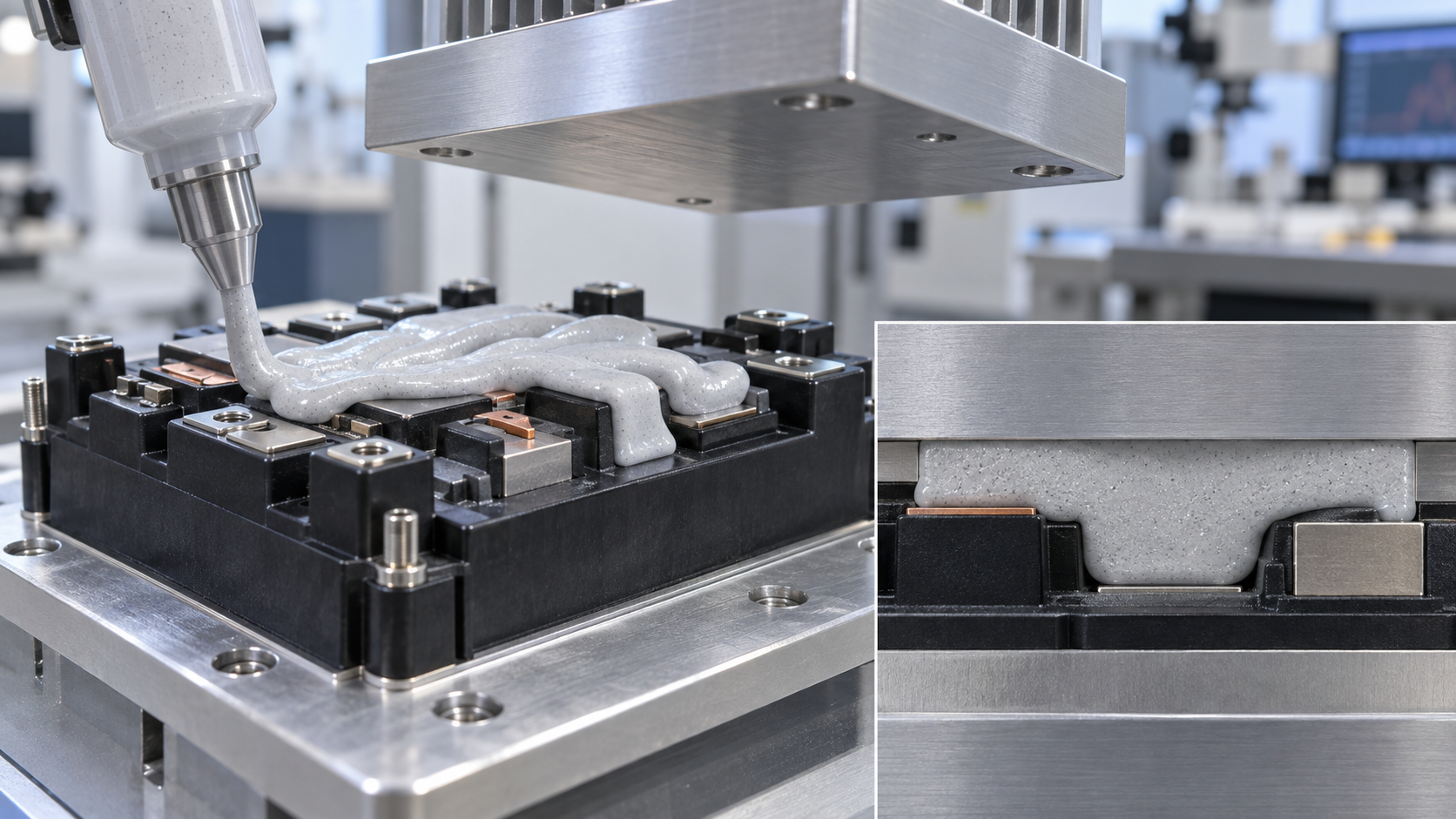
- What thermally conductive pastes and gap fillers are, in three lines
- Make-up: thermally conductive filler and resin
- A materials engineer's view (1): there is a limit to how much filler can be packed
- The heat path: thermal conductivity and interface resistance
- A materials engineer's view (2): thin layers are ruled by the interface, thick layers by the material
- Reading a conductivity number: standards and test conditions
- The weak points of grease and paste: pump-out and dry-out
- Gap fillers: applied as a liquid, then cured
- A materials engineer's view (3): to cure or not to cure is a fork in reliability
- Use in automotive and EV batteries
- Selection axes and how evaluation is done
- What is still hard, and what we could not confirm
- Glossary / References / Claim-to-source audit
Sourced = a statement in published material (link given)
Our calculation = a figure this article derived, with the assumptions spelled out
Not yet confirmed = a plan or target with no confirmed track record
Structural readings and materials-design interpretations are marked separately as Commentary.
Product values such as thermal conductivity are the manufacturer's stated values, given with the test standard, test condition and revision date of the source; products are not ranked against each other.
1. What thermally conductive pastes and gap fillers are, in three lines
Under a microscope, the surfaces of a heat-generating part and of the heat sink that cools it are rough and touch only at points. Air fills the gaps and conducts heat poorly. A material that fills such gaps is called a thermal interface material (TIM). This article covers two kinds of TIM: paste-type (grease) and liquid-applied gap fillers. For the whole family of TIMs see our explainer on thermal interface materials, and for sheet products see our explainer on thermal pads.
- Grease and paste: a material applied in a thin layer (usually 50 µm or less) that conforms to surface roughness and stays fluid rather than setting. Laird's material describes them as having a thermal conductivity of 0.5 to 7 W/(m·K), silicone-based or not, filled with fillers such as alumina, boron nitride (BN) and zinc oxide (ZnO), and applied by dispensing or printingSourced [Ref. 1].
- Gap fillers: materials for larger gaps. Laird's material says gaps of 0.25 to 5 mm, thermal conductivity of 0.5 to 10 W/(m·K), usually silicone-based, filled with BN, ZnO, alumina and the like, supplied on rolls, as sheets, or in cartridges for automated dispensingSourced [Ref. 1]. This article focuses on the form dispensed as a liquid.
- The theme here: a thermal-conductivity number is meaningless unless it comes with the test standard and conditions. Even at the same conductivity, actual heat removal changes with how it is applied, its thickness and its reliability (such as pump-out) (this article's framing).
| Item | Grease and paste | Gap filler (liquid) |
|---|---|---|
| Gap filled | Thin (usually 50 µm or less; assumes flat surfaces and constant pressure) | Thick (0.25 to 5 mm). Fills parts of different heights in one go |
| Conductivity range (Laird's summary) | 0.5 to 7 W/(m·K) | 0.5 to 10 W/(m·K) |
| State | Does not set (stays fluid). Viscosity falls under shear, and it resists sagging | Many products are applied as two components or similar and cure into a soft elastic body (gel) |
| Weak points named | Pump-out, dry-out | Mixing, de-airing, voids, working time, control of cure |
Laird technical material [Ref. 1] and this article's grouping. Sourced (the ranges are Laird's general summary, not the stated values of individual products).
The material with the highest conductivity number is not necessarily the one that cools best. Laird's material itself shows in a chart that the TIM with the lowest thermal resistance is not necessarily the one with the highest thermal conductivity [Ref. 1]. Read a number together with the standard and conditions it was measured under, the thickness at which it will be used, and whether it holds up in use.
2. Make-up: thermally conductive filler and resin
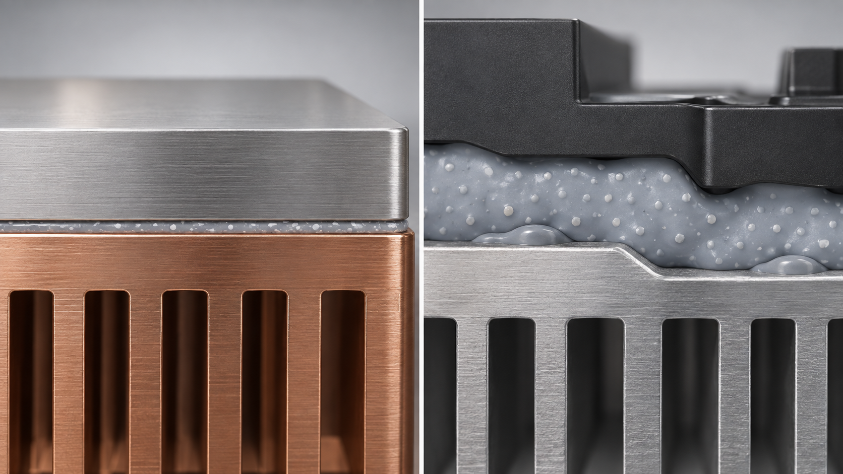
A thermally conductive paste or gap filler is a composite in which thermally conductive inorganic particles (filler) are packed at a high fraction into a resin (the matrix) that conducts heat poorly. Laird's material says filler above 90% by mass is not unusual, that it requires sophisticated packing, and that several fillers, polymers and additives are combinedSourced [Ref. 1].
Kinds of thermally conductive filler
| Filler | Thermal conductivity (literature value) | What the sources say |
|---|---|---|
| Alumina (aluminium oxide, α-Al₂O₃) | 36 W/(m·K) | Widely used commercially as a thermally conductive filler for its balance of conductivity, cost and high electrical resistance [Ref. 15]. Dow's TC-4525 CV is described as using “treated alumina” [Ref. 5] |
| Aluminium nitride (AlN) | 100 to 300 W/(m·K) | Higher conductivity than alumina or BN, but hydrolyses with moisture and releases corrosive ammonia. Resonac developed a filler whose surface treatment cut ammonia release to one ten-thousandth or less (July 2020; the company's own measurement method) [Ref. 9] |
| Hexagonal boron nitride (hBN) | 300 W/(m·K) (high in the in-plane direction of the crystal) | A graphite-like structure, white and electrically insulating. Aspect ratio (plate length to thickness) of 2:1 to 30:1. Heat flow depends on particle orientation (3M) [Ref. 10] |
| Zinc oxide (ZnO) | A number was not confirmed in this article | Listed by Laird, with BN and alumina, as a filler for gap fillers and greases [Ref. 1]. Also listed as a grease filler [Ref. 12] |
| Silver (Ag), copper (Cu) | 427 / 398 W/(m·K) | High conductivity, but they conduct electricity too, so they are hard to use where insulation is needed. Silver and copper are used as grease fillers in some examples [Ref. 11, 12] |
Conductivities are the “typical room-temperature values” in Table 2 of the review by Wang et al. (Nanomaterials 2022) [Ref. 11]; they are literature values for the crystal or bulk material. Real particles vary with purity, surface and orientation, and these are not the conductivity of a composite with resin. Sourced (typical literature values).
Choosing the resin (matrix)
The resin supports the filler and sets how the material applies and how soft it stays in use. Dow's TC-4525 CV is an addition-cure system with a silicone gel matrix cured with a platinum catalyst. The company explains that addition-cure materials give no by-products and cure at a constant rate and without exotherm regardless of section thickness or confinement [Ref. 5]. Henkel's LOCTITE TLB 9300 APSi is a two-component polyurethane thermally conductive adhesive [Ref. 4]. There are also non-silicone gap fillers for silicone-sensitive devices, and the paper discussed in chapters 7 and 9 compares how the two age [Ref. 13]. For silicone and polyurethane chemistry, see our explainers on silicones and on polyurethanes and elastomers.
Dow's TC-4525 CV data sheet gives a cured density of 2.9 g/cm³ and a make-up of “silicone gel matrix plus treated alumina” [Ref. 5]. Let us work back to the volume fraction of aluminaOur calculation.
- Assumption: silicone density 0.97 g/cm³ and alumina density 3.95 g/cm³ (both general values we assumed, not values in the data sheet)
- Volume fraction: φ = (2.9 − 0.97) / (3.95 − 0.97) = about 0.65 (65 vol%)
- Mass fraction: 0.65 × 3.95 / 2.9 = about 0.88 (88 wt%)
Assumptions and limits: the real formulation may contain components other than alumina (additives, fillers of several particle sizes), so the value is a guide. Even so, a formulation that is about 90% particles by mass and about two thirds by volume is of the same order as Laird's statement that more than 90% by mass is not unusual.
3. A materials engineer's view (1): there is a limit to how much filler can be packed
The conductivity of a composite is set by the filler's conductivity, its fraction, particle shape and size, and how well particles connect. The review by Mumtaz et al. (Heliyon 2024) says these have a large effect and that theoretical models do not fully capture particle interactions and interface complexity [Ref. 15]. Even so, two classical models introduced in that review show how much conductivity changes with fill fraction (our commentary).
| Filler volume fraction | Maxwell-Eucken (assumes isolated particles) | Bruggeman (accounts for particle interaction) |
|---|---|---|
| 30 vol% | 0.45 W/(m·K) | 0.57 W/(m·K) |
| 50 vol% | 0.78 W/(m·K) | 1.4 W/(m·K) |
| 60 vol% | 1.1 W/(m·K) | 2.6 W/(m·K) |
| 65 vol% | 1.3 W/(m·K) | 3.5 W/(m·K) |
| 70 vol% | 1.5 W/(m·K) | 4.9 W/(m·K) |
Our calculation. The equations are (6) and (9) of the review [Ref. 15]. Filler conductivity 36 W/(m·K) (alumina, Ref. 11); matrix conductivity 0.2 W/(m·K) (our assumption); interface thermal resistance ignored.
Three things can be read from this calculation.
- At low fill, particles are isolated and the rise is small. At 30 vol%, conductivity is only 2 to 3 times that of the neat resin (assumed 0.2).
- At high fill, where particles start to connect, it climbs steeply. In the model that accounts for particle interaction, going from 50 to 70 vol% takes it from 1.4 to 4.9, about 3.4 times. The review also says the Maxwell-Eucken equation suits “low filler fractions and isolated particles”, while at high fill an equation that accounts for interaction, such as Bruggeman's, is more suitable [Ref. 15].
- The measured value lies between the two equations. Dow's 2.6 W/(m·K) for TC-4525 CV (transient method) [Ref. 5] falls, at our back-calculated fraction (about 65 vol%), between the two models' values (1.3 and 3.5). But this uses an assumed alumina grade and matrix conductivity, and we do not claim agreement.
Assumptions and limits: this calculation idealises particles as simple spheres with no interface thermal resistance between particle and resin. In reality, the difficulty of heat crossing the interface, particle shape and surface treatment decide the result strongly (the review also stresses the design of contacts between fillers and surface treatment).
On the other hand, the more particles are added, the stiffer and stickier the paste gets, until it cannot be applied. So formulation centres on techniques such as combining large and small particles to pack without gaps (particle-size distribution design), surface treatment so particles blend with the resin, and mixing in particles of different shapes, such as platelet BN. Laird's material likewise says filler and matrix “work together”, and are carefully designed for packing and deflection [Ref. 1]. 3M says that with BN, the same conductivity can be reached with far less mass than with alumina, which lowers material density. In its example (a PA66 plastic compound), 70 wt% alumina gives a specific gravity of 2.3 and 40 wt% BN gives 1.4, about 40% lighterSourced (a company claim; a plastics example, not a paste) [Ref. 10].
4. The heat path: thermal conductivity and interface resistance
The thermal resistance across a TIM is the sum of the material itself (thickness / conductivity) and the boundary between the material and the mating surfaces (contact resistance, interface thermal resistance). Laird's material gives Rth = L/k + Rc (L: thickness, k: thermal conductivity, Rc: contact resistance) and shows in a chart that the share of contact resistance in the total changes with thickness [Ref. 1]. The Nanomaterials review gives the same relation (BLT/k_TIM + R_C1 + R_C2) and says the thinner the bond line (BLT) and the higher the conductivity, the lower the thermal resistance [Ref. 12]. The derivation and the unit pitfalls (W/(m·K), cm²·K/W, K/W) are covered in our explainer on thermal interface materials.
Dow's material explains that silicone has a low surface tension and wets most surfaces, which can lower the contact resistance against the substrate [Ref. 5]. DuPont's material says surface roughness creates microscopic air pockets that impede heat transfer, and that a TIM needs the softness and conformability to fill voids [Ref. 2].
Using Laird's example (contact resistance Rc = 0.15 °C·in²/W, thickness 0.75 mm) [Ref. 1], we compute thermal resistance under several conditionsOur calculation. Since 1 °C·in²/W = 6.4516 cm²·K/W, Rc = 0.15 × 6.4516 = about 0.97 cm²·K/W.
| Condition | Material resistance L/k | Contact resistance Rc | Total | Contact share |
|---|---|---|---|---|
| Gap filler, thickness 3 mm, k = 3 | 10.0 cm²·K/W | 0.97 | 11.0 | about 9% |
| Gap filler, thickness 0.75 mm, k = 3 | 2.5 | 0.97 | 3.5 | about 28% |
| Gap filler, thickness 0.75 mm, k = 10 | 0.75 | 0.97 | 1.7 | about 56% |
| Grease or paste, thickness 50 µm, k = 3 | 0.17 | 0.97 | 1.1 | about 85% |
Assumptions and limits: Rc was taken as the same 0.97 cm²·K/W in every case, but real contact resistance changes greatly with surface roughness, pressure and wetting. Thicknesses and conductivities are our examples, not values of real products.
5. A materials engineer's view (2): thin layers are ruled by the interface, thick layers by the material
The calculation above shows that what is asked of the material changes with gap thickness (our commentary).
- Thick gaps (gap fillers): the material's own resistance dominates. At 3 mm, contact resistance is only about 9% of the total. Here raising conductivity (filler type and amount) tells directly. A thick layer also makes filler weight (density) a design constraint.
- Thin gaps (grease, paste): contact resistance dominates. At 50 µm, the material's resistance is about 15% of the total and the rest is interface. Raising conductivity from 3 to 10 lowers the total only about 10%, from 1.13 to 1.02 (from the calculation above). Here wetting of the surface, a viscosity and thixotropy that allow thin application, and keeping that thinness over a long time decide the result.
- In between (0.75 mm): raising conductivity 3.3 times from 3 to 10 cuts the total from 3.5 to 1.7, about half. The contact share rises from 28% to 56%, so the benefit is smaller than the rise in conductivity.
Laird's material, too, states in a chart that the TIM with the lowest thermal resistance is not necessarily the one with the highest thermal conductivity [Ref. 1]. From this one can say that development of pastes (thin layers) centres on the interface and reliability, while development of gap fillers (thick layers) centres on conductivity, filling and density (our commentary).
6. Reading a conductivity number: standards and test conditions
A data-sheet value of “3 W/(m·K)” means different things depending on the method and conditions it was measured under. Here we look at two commonly cited standards and at how real data sheets are written.
(1) ASTM D5470: heat flow through the thickness, at steady state
The title of ASTM D5470-17 (reapproved 2024 edition, status Active) is “Standard Test Method for Thermal Transmission Properties of Thermally Conductive Electrical Insulation Materials”Sourced [Ref. 7]. The scope and significance statements published on the ASTM page can be summarised as follows.
- What it measures: the steady-state thermal impedance, from which an “apparent thermal conductivity” is calculated. “Thermal conductivity” strictly applies to homogeneous materials, and thermally conductive insulating materials are usually heterogeneous, hence “apparent”.
- Material types: Type I is “viscous liquids” such as greases, pastes and phase change materials; Type II is viscoelastic solids such as gels and soft or hard rubbers; Type III is elastic solids such as ceramics and metals.
- Treatment of interface resistance: an apparent conductivity can be calculated from thermal impedance and thickness only when interfacial resistance is negligible against the specimen's (nominally under 1%). If thermal impedance is measured at several thicknesses and plotted against thickness, the inverse of the slope is the apparent thermal conductivity and the intercept at zero thickness is the sum of the contact resistances of the two surfaces.
- Limit: the method imposes an idealised heat flow, and the page cautions that the measured thermal impedances cannot be applied directly to most practical applications.
(2) ISO 22007-2: the hot disc (transient plane source) method
The title of ISO 22007-2:2022 (third edition, June 2022) is “Plastics — Determination of thermal conductivity and thermal diffusivity — Part 2: Transient plane heat source (hot disc) method”Sourced [Ref. 8]. The abstract on the ISO page says the method determines the thermal conductivity and thermal diffusivity of plastics, gives guidance for testing homogeneous and isotropic materials (and anisotropic materials with a uniaxial structure), and suits thermal conductivity in roughly the range 0.010 to 500 W/(m·K). It also notes that to determine the through-thickness thermal resistance or apparent thermal conductivity of an inhomogeneous product, ISO 8301, ISO 8302 and ISO 472 should be consulted [Ref. 8].
As test-method challenges, Laird's material lists that ASTM D5470 is for thick materials, cannot measure anisotropy, and is difficult for thin, high-performance materials such as grease and phase change materials; that anisotropy by the hot disc method (ISO 22007-2) needs the specific heat; and that laser flash needs expensive equipment and complicated sample preparationSourced [Ref. 1].
(3) In real data sheets
The table below sorts the gap-filler material we could confirm by the conductivity figure and how the method is stated.
| Product (maker) | Stated conductivity | Stated test method | Date or edition of the source | Source |
|---|---|---|---|---|
| LOCTITE TLB 9300 APSi (Henkel) | 3.0 W/(m·K) | ASTM D5470 | Product information sheet (no edition date given) | [Ref. 4] |
| DOWSIL TC-4525 CV (Dow) | Product page: 2.5 W/(m·K) Data sheet features: > 2.5 W/(m·K) Data sheet typical properties: 2.6 W/(m·K) | Typical properties say “by Transient method” | Product page (checked October 2026) / data sheet Form No. 11-3589-01 A (© 2017) | [Ref. 5, 6] |
| GAP FILLER TGF 1000 / 1500 / 3600 (BERGQUIST, Henkel) | 1.0 / 1.8 / 3.6 W/(m·K) | No test method stated in the catalogue | Catalogue as of January 2019 | [Ref. 3] |
All Sourced (manufacturer's stated values). Methods, conditions and editions differ, so the size of a number cannot rank products.
For Dow's TC-4525 CV, the product page says 2.5, the data sheet's feature list says > 2.5, and the typical-properties table says 2.6 (transient method): three figures for one product. None is necessarily wrong; it reads as a promised floor value and a typical value being mixed (our interpretation; the company cautions that typical properties are not for use in preparing specifications) [Ref. 5]. We show the 2.6 versus 2.5 gap (about 4%) only as an example of the spread that method and wording can cause, and do not judge which is “right”.
Note that a 3.0 measured by ASTM D5470 and a 2.6 measured by a transient method cannot be compared on the same footing. D5470 measures a specimen clamped between two plates with heat flowing through the thickness, and it involves how interface resistance is handled. A transient method (such as hot disc) measures from how heat spreads inside the specimen, so it excludes interface resistance and presumes a homogeneous, isotropic material. The same material can therefore give different numbers, and neither equals the thermal resistance once assembled into a product (our commentary).
7. The weak points of grease and paste: pump-out and dry-out
Because grease and paste do not set and stay fluid, they apply thin and conform to surfaces, but they tend to break down with continued use.
- Pump-out: the review by Xing et al. (Nanomaterials 2022) says that under thermomechanical stress, thermal grease tends to be pumped out of the gap because of its high fluiditySourced [Ref. 12].
- Separation (dry-out): the same review says that at high temperature, the filled particles and the matrix separate and the ability to conduct heat is lost [Ref. 12].
- Laird's summary: it lists among the desirable properties of grease and phase change materials resistance to pump-out, low outgassing and low bleeding, and long-term reliability [Ref. 1].
- A metal example: Indium Corporation says gallium-based liquid metal is prone to pump-out and that its more viscous “liquid metal paste” spreads more predictably. For its metal TIM “Heat-Spring” it lists as a feature “no pump-out or bake-out, as with thermal greases” (a company claim) [Ref. 14].
A material that cures into a soft elastic body after application, like a gap filler, sits on the side that resists pump-out. Laird lists, among gap-filler features, an option of “cured in place for improved reliability” [Ref. 1]. But this does not mean that curing prevents pump-out. The paper below points out that even a cured gap filler raises a pump-out concern if its thermal expansion is large.
How gap fillers change with heat: silicone-based and silicone-free
Chowdhury et al. (Materials 2021) heat-aged commercial silicone-based and silicone-free gap fillers at 125 °C for 2000 hours (the paper cites the high-temperature storage standard JESD22-A103E, Condition A) and compared changes in mechanical, thermal and dielectric propertiesSourced [Ref. 13].
- Silicone-free: it became hard on heat ageing. The paper says that prolonged heat exposure that hardens it could crack adjacent surfaces and voids could form, affecting thermal performance [Ref. 13].
- Silicone-based: its dynamic modulus rose after ageing but it stayed viscoelastic, and its mechanical and thermal properties at high temperature were judged better than the silicone-free one's [Ref. 13].
- However: because the silicone-based one has higher thermal expansion, pump-out problems might arise, which the paper says needs to be considered in package design [Ref. 13].
- Electrical properties: in dielectric behaviour the silicone-free one conducts less, making it suited to uses where electrical insulation is paramount or to silicone-sensitive devices [Ref. 13].
DuPont's material also says certain epoxies and the like harden and delaminate at 150 °C and can fail thermally, so most TIM1 materials are silicone-based, with filler surface treatments designed to keep them from embrittling and changing their gel-like character over long periods at extreme temperatures [Ref. 2].
8. Gap fillers: applied as a liquid, then cured
Henkel describes its BERGQUIST GAP FILLER (liquid) as a two-component thermally conductive gap-filling material that can be applied by dispenser, giving high freedom of shape, and that puts no load or stress on parts or boards during assembly. After curing at room temperature or with heat it becomes a low-modulus thermally conductive polymer that provides a thermal interface without air gapsSourced [Ref. 3].
| Product (manufacturer's stated) | Conductivity | Density | Hardness | Cure | What the source says | Source |
|---|---|---|---|---|---|---|
| GAP FILLER TGF 1000 (Henkel, as of January 2019) | 1.0 W/(m·K) | 1.6 g/cm³ | Shore 00: 30 | 1 to 2 hours at room temperature, about 5 minutes at 100 °C | Two-component silicone type. Becomes a tack-free solid resin. Dielectric strength 500 V/mil | [Ref. 3] |
| GAP FILLER TGF 1500 (same) | 1.8 W/(m·K) | 2.7 g/cm³ | Shore 00: 50 | About 5 hours at room temperature | High viscosity with little sag after application. Dielectric strength 400 V/mil | [Ref. 3] |
| GAP FILLER TGF 3600 (same) | 3.6 W/(m·K) | 3.0 g/cm³ | Shore 00: 35 | — | Highest conductivity in the series. Relatively low viscosity, so less load on parts at assembly. Dielectric strength 275 V/mil | [Ref. 3] |
| LOCTITE TLB 9300 APSi (Henkel) | 3.0 W/(m·K) (ASTM D5470) | 2.65 g/cm³ (ASTM D792) | — | Room-temperature cure | Two-component polyurethane thermally conductive adhesive. Viscosity 160 Pa·s (2.4 1/s, DIN 53019). Lap shear strength 2.6 MPa (Al-Al), breakdown voltage 16 kV/mm. Self-levelling | [Ref. 4] |
| DOWSIL TC-4525 CV (Dow, data sheet © 2017) | 2.6 W/(m·K) (transient method) | 2.9 g/cm³ (cured) | Shore 00: 40 | 120 min at 25 °C, 10 min at 80 °C. Working time 40 min at 25 °C | Two-part, 1:1. Mixed viscosity 217 Pa·s, thixotropic index 4.0 (steady shear 1 1/s / 10 1/s). Dielectric strength 12 kV/mm. Holds vertical position. Controlled silicone volatility (< 100 ppm, product page) | [Ref. 5, 6] |
Each company's material. Sourced (manufacturer's stated). Methods and editions differ, so no ranking is possible. The catalogue does not state the test method for the TGF conductivities. Dielectric strength is given in V/mil in one source and kV/mm in others, so we converted (below).
Since 1 mil = 0.0254 mm, 1 V/mil = 1 / 0.0254 V/mm = about 39.4 V/mmOur calculation. TGF 1000's 500 V/mil = about 19.7 kV/mm, TGF 1500's 400 V/mil = about 15.7 kV/mm, and TGF 3600's 275 V/mil = about 10.8 kV/mm. In the same unit they can be read alongside TLB 9300 APSi's 16 kV/mm and TC-4525 CV's 12 kV/mm, but the test conditions (specimen thickness, voltage ramp) could not be confirmed in each source, so we do not rank them.
Applying, mixing and curing: what matters in use
Dow's TC-4525 CV data sheet says the following about use [Ref. 5].
- Mixing: the two parts are mixed in the right ratio by weight or volume. Light-coloured streaks or marbling indicate inadequate mixing.
- De-airing: automated airless dispense equipment can reduce the need to de-air. If de-airing is needed, a vacuum of more than 8 inHg (about 27 kPa) for 10 minutes or until bubbling subsides is given as an example.
- Filler settling: the formulation is designed to minimise settling, but after several weeks filler may rarely settle to the bottom; in that case the container contents should be thoroughly mixed before use.
- Working time and cure: cure begins on mixing, with viscosity rising and then gelation. Pot life is defined as “the time for viscosity to double”; working time is 40 minutes at 25 °C, and cure takes 120 minutes (25 °C) or 10 minutes (80 °C). No post-cure is needed and the material can go into service at once at operating temperatures of −45 to 150 °C.
- Storage: keep moisture away, keep containers tightly closed, and minimise head space. Shelf life follows the “Use By” date on the label.
Henkel's material positions TGF 1500 as high viscosity with little sag and TGF 3600 as relatively low viscosity with less load on parts at assembly [Ref. 3]. Even among “gap fillers”, the design of viscosity and thixotropy marks the line between ease of application and load on parts (the pressing force). For the basics of paste viscosity, thixotropy and printability, see our explainer on pastes for electronics.
9. A materials engineer's view (3): to cure or not to cure is a fork in reliability
Grease (does not set) and gap filler (sets) start from the same “paste-like thermal interface material” but differ in where reliability is weak (our commentary).
- Does not set: applies thin, with good interface wetting. The weak points are pump-out and separation, with the high fluidity itself the cause [Ref. 12].
- Sets: keeps its shape and resists pump-out. The weak points are modulus after cure and thermal expansion. Silicone-free types tend to harden on high-temperature ageing, which can lead to cracks and voids [Ref. 13]. Silicone-based types stay soft but expand more [Ref. 13].
- Keeping it soft: DuPont says its TIM1 materials are designed to keep a gel-like consistency after cure with a low modulus, so warpage-induced stress is not passed to the chip [Ref. 2]. Dow's TC-4525 CV also lists as features that it is soft and compressible once cured, with low compression stress [Ref. 5].
There are three points a materials engineer should watch.
- Resin chemistry sets the modulus and the heat resistance. Addition-cure silicone gives no by-products and cures uniformly even in deep sections [Ref. 5]. But volatile silicone components can affect contacts and the like, so Dow lists “controlled silicone volatility (< 100 ppm)” as a feature [Ref. 6].
- Filler surface treatment must reconcile “blending with the resin” and “not embrittling”. DuPont says surface treatment of the filler is needed to avoid embrittlement and changes in gel character over long periods at high temperature [Ref. 2].
- Expansion mismatch creates stress in use. That a CTE difference causes displacement and delamination is the same idea as in our explainer on the coefficient of thermal expansion.
10. Use in automotive and EV batteries
Around automotive electronics and batteries, demands pile up: fill parts of different heights in one go, apply automatically, withstand vibration and temperature change, and be light. Liquid gap fillers are used for these.
- Around batteries (Henkel): LOCTITE TLB 9300 APSi lists thermal management and structural bonding in EV batteries as an application: between cells and modules and between cells and cooling systems. It is described as low density, suited to lightweight optimisation, room-temperature curing and solvent-freeSourced [Ref. 4]. It is supplied in 400 mL cartridges, 20 L pails and 200 L drums.
- Battery packs and heat sinks (DuPont): DuPont lists, in its TIM2 portfolio (the thermal path from the outside of the package to the heat sink), a formulated TIM2 for automotive applications between battery packs and heat sinks. It describes high-power electronics for EV battery charging and discharging as generating considerable heat, with harsh temperature extremes in vehicle operating environments adding to the challenge [Ref. 2].
- Automotive control units (Dow): TC-4525 CV is a 2.5 W/(m·K)-class gap filler for automotive components such as engine and transmission control units, moving heat from parts on a printed circuit board to a heat sink. It is designed for automated meter-mix dispensing, and lists long-term performance stability during temperature cycling as a feature [Ref. 5].
As a hypothetical example, let us calculate gap filler between the underside of a battery module and a cooling plateOur calculation.
- Assumptions: contact area 0.3 m², mean thickness 1.5 mm, heat from the module 300 W, thermal conductivity 3.0 W/(m·K), density 2.65 g/cm³ (borrowing Henkel's stated values for TLB 9300 APSi [Ref. 4]), contact resistance 0.97 cm²·K/W as in chapter 4
- Volume and mass of material: 0.3 m² × 1.5 mm = 4.5×10⁻⁴ m³ = 450 cm³. 450 × 2.65 = about 1.2 kg per module
- Temperature drop across the material: heat flux q = 300 W / 0.3 m² = 1,000 W/m². ΔT = q × L / k = 1,000 × 1.5×10⁻³ / 3.0 = about 0.5 K
- Temperature drop across contact resistance: 0.97 cm²·K/W = 9.7×10⁻⁵ m²·K/W. ΔT = 1,000 × 9.7×10⁻⁵ = about 0.1 K. Together about 0.6 K
Assumptions and limits: area, thickness and heat are values we assumed, not those of any real battery module. Voids and thickness variation are not considered.
What this example shows is that in cooling large areas at low heat flux, the temperature drop across the material itself is surprisingly small (our commentary). What matters instead is more than the conductivity figure: filling the gap evenly and without voids (application and de-airing), the 1.2 kg of weight (density), and holding up over the long term against vibration, temperature change and electrical insulation. Henkel's listing of “low density”, “structural bonding” and “breakdown voltage” as features of TLB 9300 APSi [Ref. 4] fits this view.
11. Selection axes and how evaluation is done
The following nine axes organise the choice (this article's grouping).
| Axis | What to look at | What the sources say |
|---|---|---|
| 1. Thermal resistance | Conductivity × thickness plus interface. The method and conditions behind “3 W/(m·K)” | ASTM D5470 can separate apparent conductivity from interface resistance. The TIM with the lowest thermal resistance is not necessarily the one with the highest conductivity [Ref. 1, 7] |
| 2. Gap size | Thickness, tolerance, warpage | Laird: gap fillers 0.25 to 5 mm, grease 50 µm or less [Ref. 1] |
| 3. Viscosity, thixotropy, sag | Ease of application, holding on vertical surfaces, load on parts | TGF 1500 has high viscosity with little sag; TGF 3600 has low viscosity and less load on parts [Ref. 3]. TC-4525 CV holds its position on vertical surfaces [Ref. 5] |
| 4. Cure | Working time, cure conditions, post-treatment | TC-4525 CV: 40 min working time, 120 min at 25 °C / 10 min at 80 °C, no post-cure [Ref. 5] |
| 5. Reliability | Temperature cycling, high-temperature ageing, pump-out, dry-out | Cured types resist being squeezed out. Silicone-free types tend to harden at high temperature; silicone-based types expand more [Ref. 12, 13] |
| 6. Electrical insulation | Dielectric strength, volume resistivity | TGF: 275 to 500 V/mil; TLB 9300 APSi: 16 kV/mm; TC-4525 CV: 12 kV/mm (test conditions not confirmed in each source) [Ref. 3-5] |
| 7. Density (weight) | Affects weight over large areas | TLB 9300 APSi lists low density as a feature; TGF is 1.6 to 3.0 g/cm³ [Ref. 3, 4] |
| 8. Chemistry | Silicone or not, volatiles | Silicone volatiles controlled (Dow). Silicone-free types for silicone-sensitive devices [Ref. 6, 13] |
| 9. Adhesion and rework | Whether structural bonding is needed, ease of rework | TLB 9300 APSi has high adhesion, with lap shear strength 2.6 MPa (Al-Al). Laird lists “easy to rework” as a gap-filler feature [Ref. 1, 4] |
All Sourced (a summary of what each source states). The grouping into axes is this article's own.
On evaluation, Laird's material says that measuring thermal resistance needs to be combined with a thermal test vehicle (TTV) and real-application tests [Ref. 1]. Standard tests (ASTM D5470, ISO 22007-2) are baselines for comparing materials, not guarantees of the temperature of an actual device; that is the thrust of both standards' pages [Ref. 7, 8].
- Paste (grease) fills thin gaps and gap fillers fill thick ones. Laird summarises gap fillers as 0.25 to 5 mm and grease as 50 µm or lessSourced
- The formulation packs roughly 90% particles by mass into resin. Back-calculating from density, TC-4525 CV reads as about 65% alumina by volumeOur calculation
- Thin layers are ruled by the interface; thick layers by the material. Contact was about 85% at 50 µm and about 9% at 3 mmOur calculation
- A conductivity number must be read with its method. TLB 9300 APSi is 3.0 by ASTM D5470, TC-4525 CV is 2.6 by a transient method, and TGF states no methodSourced
- Grease is weak on pump-out and separation. Cured gap fillers avoid them more easily, but have issues of thermal expansion and, for silicone-free types, hardeningSourced
- In a battery cooling plate the temperature drop across the material is small (about 0.6 K in our example); even filling, weight and long-term reliability matterOur calculation
12. What is still hard, and what we could not confirm
(1) Many sources do not state the conductivity test method
The conductivities of Henkel's GAP FILLER TGF series have no test method in the catalogue [Ref. 3]. Dow's figures also differ among the product page, the data sheet's feature list and the typical-properties table [Ref. 5, 6]. This article does not line up conductivities from different sources to rank products.
(2) The conductivity of zinc oxide (ZnO) could not be confirmed
ZnO is listed by Laird as a filler [Ref. 1], but we found no numerical conductivity in the sources checked. The filler values in the table are literature values for crystals from a review, not values for composites.
(3) A standard pump-out test and quantitative data could not be confirmed
The review by Xing et al. cites a paper on accelerated pump-out testing (Wunderle et al., 2019) [Ref. 12], but we have not checked that paper. The number of a pump-out test standard and quantitative comparisons between materials could not be confirmed within this survey. The statement in the paper by Chowdhury et al. that pump-out problems might arise with silicone-based types is also a concern inferred from the size of the thermal expansion, not a result confirmed by experiment [Ref. 13].
(4) Some sources are old editions
Henkel's BERGQUIST catalogue is as of January 2019, and Dow's TC-4525 CV data sheet is a 2017 edition (we used a copy posted by a distributor; the PDF on Dow's own site could not be retrieved). That may also explain why the numbers differ from Dow's product page. Check the latest specifications with each company.
(5) Mass-production status of the aluminium nitride filler
Resonac's July 2020 news release said it planned to start mass production from 2023. We could not confirm the later production status within this survey, so we treat it as Not yet confirmed [Ref. 9].
(6) 3M's example is a plastic composite, not a paste
The weight-saving figures for BN (specific gravity 2.3 versus 1.4) are for a PA66 plastic and are not values for grease or gap filler [Ref. 10]. We treat them as a company claim.
(7) What is not covered
Thermal-runaway protection and flame retardancy of battery packs (such as UL 94), regulations by country, the details of adhesive strength of thermally conductive adhesives, individual silicone-free products, and market size and share (market-research estimates) are not covered in this article.
13. Glossary
- TIM
- Thermal Interface Material. A material that fills the gap between a heat-generating part and a heat-dissipating part.
- TIM1 / TIM2
- Between the chip and the lid (TIM1) / between the outside of the package and the heat sink (TIM2).
- Thermal grease
- A paste-like TIM that does not set. Used in thin layers.
- Gap filler
- A soft TIM for large gaps. Some are applied as a liquid and then cured.
- Filler / matrix
- The particles that carry heat / the resin that holds them.
- Thermal conductivity
- How readily a material conducts heat. Unit W/(m·K). The larger, the better it conducts.
- Apparent thermal conductivity
- For a heterogeneous material, the value calculated from thermal impedance and thickness (ASTM D5470 term).
- Thermal impedance / thermal resistance
- How hard it is for heat to pass; includes thickness and interface resistance.
- Contact resistance (interface thermal resistance)
- Difficulty of heat transfer at the boundary between material and mating surface.
- BLT
- Bond line thickness. The thickness of the TIM layer as actually used.
- Steady-state / transient method
- Measuring after heat flow stabilises / measuring from changes over time (such as hot disc).
- Pump-out
- Grease being squeezed out of the gap by thermal stress.
- Dry-out
- Resin and particles separating so that particles dry and cannot conduct heat (this article's term).
- Bleed
- Oil or similar seeping out of a material.
- Thixotropic index
- A ratio of viscosities at different shear. Dow states its definition as “1 1/s over 10 1/s”.
- Addition cure
- Cure that proceeds without by-products, with a platinum catalyst for example. Common for silicones.
- Working time (pot life)
- Time usable after mixing. Dow defines it as the time for viscosity to double.
- Shore 00
- A hardness scale for very soft materials.
- Aspect ratio
- Ratio of a particle's length to thickness. Large for platelet BN.
- Dielectric strength
- The electric field a material withstands without conducting. Given in kV/mm or V/mil.
14. References
- Laird (J. Strader et al.) "Thermal Interface Materials (TIMs) and Challenges Faced by TIM Suppliers", Thermal & Fluids Analysis Workshop (TFAWS) 2014 (presentation PDF hosted by NASA) — s3vi.ndc.nasa.gov
- DuPont (Claire K. Wemp) "Advanced Polymer Formulations for Thermal Management of Electronic Devices" (technical article PDF) — dupont.com
- Henkel Japan "Thermal Solutions" BERGQUIST thermal interface materials catalogue (in Japanese; as of January 2019; PDF) — dm.henkel-dam.com
- Henkel LOCTITE TLB 9300 APSi Product Information Sheet (no edition date given) — dm.henkel-dam.com
- Dow Technical Data Sheet "DOWSIL™ TC-4525 CV Thermally Conductive Gap Filler", Form No. 11-3589-01 A (© 2017); copy posted by the distributor Gal Lindberg — galindberg.se
- Dow "DOWSIL™ TC-4525 CV Thermally Conductive Gap Filler", product page (checked October 2026) — dow.com
- ASTM International ASTM D5470-17(2024) "Standard Test Method for Thermal Transmission Properties of Thermally Conductive Electrical Insulation Materials" (store page; scope and significance statements checked) — store.astm.org
- ISO ISO 22007-2:2022 "Plastics - Determination of thermal conductivity and thermal diffusivity - Part 2: Transient plane heat source (hot disc) method" (abstract on the ISO page checked) — iso.org
- Resonac (Showa Denko) "Development of a moisture-resistant, high-thermal-conductivity aluminium nitride filler", news release, 14 July 2020 (in Japanese) — resonac.com
- 3M "3M™ Boron Nitride Cooling Fillers" brochure (in Japanese; PDF) — multimedia.3m.com
- Wang J. et al. "Development and Perspectives of Thermal Conductive Polymer Composites", Nanomaterials 2022, 12(20), 3574 (DOI 10.3390/nano12203574); open access (PMC) — pmc.ncbi.nlm.nih.gov
- Xing W. et al. "Recent Advances in Thermal Interface Materials for Thermal Management of High-Power Electronics", Nanomaterials 2022, 12(19), 3365 (DOI 10.3390/nano12193365); open access (PMC) — pmc.ncbi.nlm.nih.gov
- Chowdhury A. S. M. R. et al. "A Comparative Study of Thermal Aging Effect on the Properties of Silicone-Based and Silicone-Free Thermal Gap Filler Materials", Materials 2021, 14(13), 3565 (DOI 10.3390/ma14133565); open access (PMC) — pmc.ncbi.nlm.nih.gov
- Indium Corporation "Thermal Interface Materials" brochure (Form 99342 (A4) R4, PDF) — indium.com
- Mumtaz N. et al. "Fillers and methods to improve the effective (out-plane) thermal conductivity of polymeric thermal interface materials - A review", Heliyon 2024, 10(3), e25381 (DOI 10.1016/j.heliyon.2024.e25381); open access (PMC) — pmc.ncbi.nlm.nih.gov
15. Claim-to-source audit
| Claim in the text | Basis | Label |
|---|---|---|
| Laird's summary: gap fillers (gaps of 0.25 to 5 mm, conductivity 0.5 to 10 W/(m·K), usually silicone-based with BN, ZnO and alumina, supplied on rolls, as sheets or in cartridges). Grease and PCM (thin layer, usually 50 µm or less, 0.5 to 7 W/(m·K), silicone or non-silicone, BN, ZnO and alumina, dispensable or printable, shear thinning and non-slumping). That filler above 90% by mass is not unusual. Rth = L/k + Rc and the example with Rc = 0.15 °C·in²/W and 0.75 mm. That the TIM with the lowest thermal resistance is not necessarily the one with the highest conductivity. Desirable properties (pump-out resistance, low outgassing and bleeding, easy rework, a cured-in-place option). Test-method challenges (ASTM D5470 for thick materials and no anisotropy, difficulty with thin high-performance materials, hot disc and laser flash). The need for TTV and real-application tests | Reference 1 https://s3vi.ndc.nasa.gov/ssri-kb/static/resources/TFAWS-2014-PT-06.pdf | Sourced |
| Definitions of TIM1 and TIM2 and their temperature cycling (TIM1 from -40 to 150 °C, TIM2 up to about 120 °C); that the TIM2 portfolio includes an automotive material between battery packs and heat sinks; that EV battery charging and ADAS electronics generate considerable heat; that surface roughness creates microscopic air pockets; that most TIM1 materials are silicone-based and some epoxies can harden and delaminate at 150 °C; filler surface treatment; a gel-like, low-modulus design after cure | Reference 2 https://www.dupont.com/content/dam/dupont/amer/us/en/articles/corporate/Advanced%20Polymer%20Formulations%20for%20Thermal%20Management%20of%20Electronic%20Devices_r1_66.pdf | Sourced |
| Henkel's description of BERGQUIST GAP FILLER (two components, dispenser application, no stress, becomes a low-modulus thermally conductive polymer) and the specifications of TGF 1000, 1500 and 3600 (conductivity 1.0, 1.8 and 3.6 W/(m·K); density 1.6, 2.7 and 3.0 g/cm³; dielectric strength 500, 400 and 275 V/mil; Shore 00 of 30, 50 and 35; cure conditions; viscosity characteristics). That the January 2019 catalogue states no conductivity test method | Reference 3 https://dm.henkel-dam.com/is/content/henkel/brochure-bergquist-thermal-interface-materials-jp | Sourced |
| LOCTITE TLB 9300 APSi specifications (two-component polyurethane; conductivity 3.0 W/(m·K) [ASTM D5470]; density 2.65 g/cc [ASTM D792]; lap shear strength 2.6 MPa; breakdown voltage 16 kV/mm; viscosity 160 Pa·s [2.4 1/s, DIN 53019]) and applications (EV battery thermal management and structural bonding, low density, room-temperature cure, solvent-free, 400 mL cartridges, 20 L pails, 200 L drums) | Reference 4 https://dm.henkel-dam.com/is/content/henkel/product-information-sheet-loctite-tlb-9300-apsi | Sourced |
| DOWSIL TC-4525 CV data sheet (silicone gel matrix, treated alumina, platinum cure, conductivity 2.6 W/(m·K) [transient method] and "> 2.5" in the feature list, mix ratio 1:1, mixed viscosity 217 Pa·s, thixotropic index 4.0 [1 1/s / 10 1/s], density 2.9 g/cm³, working time 40 min at 25 °C, cure 120 min at 25 °C and 10 min at 80 °C, Shore 00 of 40, dielectric strength 12 kV/mm, operating range -45 to 150 °C, no post-cure, addition cure with no by-products and no exotherm, statements on mixing, de-airing, filler settling, the definition of pot life and storage, that silicone's low surface tension wets surfaces, and the caution that the values are not for specifications) | Reference 5 https://www.galindberg.se/storage/10D611EBC37BF0BE25BF1B60D1D859C20E37C6148712A9739FC46F18E6D27F64/3341282af7b547e289cb4ea7ce11ac73/pdf/media/3c8c8f8790414500b1d8fe8acb60f3ae/DOWSIL%E2%84%A2%20TC-4525%20CV%20Thermally%20Conductive%20Gap%20Filler.pdf | Sourced |
| DOWSIL TC-4525 CV product page (2.5 W/mK, two parts, cure 2 hours at 25 °C and 10 minutes at 80 °C, 40 Shore 00, silicone volatility under 100 ppm, low compression stress, thixotropic) | Reference 6 https://www.dow.com/en-us/pdp.dowsil-tc-4525-cv-thermally-conductive-gap-filler.04124945z.html | Sourced |
| The title of ASTM D5470-17(2024) and its scope and significance (steady-state thermal impedance, apparent thermal conductivity, the Type I to III classification, interface resistance under 1%, slope and intercept from a thickness series, and that results cannot be applied directly to most practical uses) | Reference 7 https://store.astm.org/d5470-17r24.html | Sourced |
| ISO 22007-2:2022 (third edition, June 2022): title and abstract (thermal conductivity and diffusivity of plastics, guidance for homogeneous and isotropic materials, about 0.010 to 500 W/(m·K), and the pointer to ISO 8301, 8302 and 472 for through-thickness thermal resistance of inhomogeneous products) | Reference 8 https://www.iso.org/standard/81836.html | Sourced |
| Aluminium nitride filler: higher conductivity than alumina or BN, the problem of hydrolysis releasing ammonia, ammonia release cut to one ten-thousandth or less by surface treatment (the company's own measurement method, not guaranteed), announced 14 July 2020, and the plan to start mass production from 2023 | Reference 9 https://www.resonac.com/jp/news/2020/07/14/266.html | Sourced |
| 3M BN cooling fillers: the structure of hBN, aspect ratio of 2:1 to 30:1, white and electrically insulating, orientation, 3.5 to 4 W/(m·K) with spherical alumina versus up to 15 W/(m·K) with BN (laser flash), and the PA66 comparison of 70 wt% alumina (specific gravity 2.3) and 40 wt% BN (1.4), about 40% lighter | Reference 10 https://multimedia.3m.com/mws/media/1983283O/3m-boron-nitride-cooling-fillers-brochure-jp-chm-bn-05-a.pdf | Sourced |
| Literature values of conductivity for fillers (silver 427, copper 398, α-alumina 36, hBN 300, AlN 100 to 300, SiC 120, BeO 230 to 330 W/(m·K)) and that metallic fillers also conduct electricity | Reference 11 https://pmc.ncbi.nlm.nih.gov/articles/PMC9611299/ | Sourced |
| The make-up of grease, pump-out under thermal stress, separation of particles and matrix at high temperature, grease fillers (Al₂O₃, ZnO, SiC, Ag, Cu), and the relation R_TIM = BLT/k + R_C1 + R_C2. The citation of Wunderle et al. on accelerated pump-out testing | Reference 12 https://pmc.ncbi.nlm.nih.gov/articles/PMC9565324/ | Sourced |
| Heat ageing of silicone-based and silicone-free gap fillers at 125 °C for 2000 hours (JESD22-A103E Condition A): the silicone-free one hardens, with a risk of cracks and voids; the silicone-based one stays viscoelastic but expands more, with a pump-out concern; differences in dielectric properties | Reference 13 https://pmc.ncbi.nlm.nih.gov/articles/PMC8269627/ | Sourced |
| Indium Corporation: that gallium-based liquid metal is prone to pump-out, the character of liquid metal paste, and the claim that Heat-Spring has no pump-out or bake-out as with thermal greases (company claim) | Reference 14 https://www.indium.com/wp-content/uploads/2025/08/TIMs-Brochure-99342-A4-R4.pdf | Sourced |
| The review by Mumtaz et al.: that fill fraction, shape and interfaces affect conductivity, the Maxwell-Eucken (equation 6) and Bruggeman (equation 9) models, that alumina is widely used commercially, and that theoretical models do not fully capture the complexity | Reference 15 https://pmc.ncbi.nlm.nih.gov/articles/PMC10862693/ | Sourced |
| Resonac's plan to start mass production of the aluminium nitride filler from 2023 (a plan as of 2020; no confirmation of later status) | Reference 9 https://www.resonac.com/jp/news/2020/07/14/266.html | Not yet confirmed |
| Converting 0.15 °C·in²/W to about 0.97 cm²·K/W and the breakdown of thermal resistance under four conditions (3 mm, k = 3: total about 11.0, contact about 9%; 0.75 mm, k = 3: about 3.5, 28%; 0.75 mm, k = 10: about 1.7, 56%; 50 µm, k = 3: about 1.1, 85%) | Our calculation. Contact resistance was assumed equal in every case. Thicknesses and conductivities are our examples, not values of real products | Our calculation |
| The volume fraction of alumina (about 65 vol%) and mass fraction (about 88 wt%) from the density of 2.9 g/cm³ of TC-4525 CV | Our calculation, based on our assumptions of 0.97 g/cm³ for silicone and 3.95 g/cm³ for alumina. The real formulation could not be confirmed | Our calculation |
| Conductivities from the Maxwell-Eucken and Bruggeman equations (0.45 to 1.5 and 0.57 to 4.9 W/(m·K) at 30 to 70 vol%) and the rise by about 3.4 times from 50 to 70 vol% | Our calculation. Filler 36 W/(m·K) (Reference 11), matrix 0.2 W/(m·K) (our assumption), interface thermal resistance ignored | Our calculation |
| Converting dielectric strength from V/mil to kV/mm (500 to about 19.7, 400 to about 15.7, 275 to about 10.8) | Our calculation (1 mil = 0.0254 mm). Test conditions could not be confirmed in each source | Our calculation |
| The battery cooling-plate example (0.3 m², 1.5 mm, 300 W, k = 3.0, density 2.65 g/cm³, giving about 1.2 kg, about 0.5 K across the material, about 0.1 K across contact, about 0.6 K in total) | Our calculation. Area, thickness and heat are our hypothetical values, not those of a real battery module. Voids and thickness variation are not considered | Our calculation |
| The conductivity of ZnO, a pump-out test standard and quantitative comparison data, the test method behind the TGF conductivities, the latest edition of Dow's data sheet, and the mass-production status of the aluminium nitride filler | Not confirmed in the public sources used, so not stated (our note) | Commentary |
| The framing that thin layers are ruled by the interface and thick layers by the material; that to cure or not to cure is a fork in reliability; the reading of Dow's three numbers as a promised floor value mixed with a typical value; the reading that in a battery cooling plate the temperature drop across the material is small; the nine selection axes | Commentary: this article's own organisation and interpretation of the published content; not views stated by the companies or institutions | Commentary |
| That the hero image and Fig. 1 are AI-generated images and that Figs. 2 to 6 are explanatory drawings | Our own note in this article | Commentary |
Last updated: 3 October 2026. Sources are limited to primary material (manufacturers' official data sheets, catalogues and product pages, standards bodies' pages, and peer-reviewed reviews and papers). Because this article includes structural readings and materials-design interpretations, these are labelled “Commentary” and kept separate from sourced facts. Product values are the manufacturer's stated values; values from different methods, conditions and editions are not lined up to rank products. The conductivity of ZnO, a pump-out test standard and quantitative data, the latest editions of the sources, and the mass-production status of the aluminium nitride filler could not be confirmed in published primary sources and are therefore not stated. The hero image and Fig. 1 are AI-generated images; Figs. 2 to 6 are vector drawings (Fig. 3 includes our calculation), and none of them shows an actual cross-section photograph or real product.