TECHNOLOGY EXPLAINER
Carbon Nanotubes
— not one material, but many, set by how they are rolled, grown and sorted
A carbon nanotube (CNT) is a sheet of graphene rolled into a tube. Whether it has one wall or several, and how it is rolled (its chirality), decides whether it behaves as a metal or a semiconductor. This article covers structure, production routes (arc, laser, CVD, super-growth and floating catalyst), separation and dispersion, how far applications in batteries, composites, wiring and transistors have progressed, and what public bodies have concluded about safety, drawing on papers, manufacturers’ official pages and documents from IARC and NIOSH.
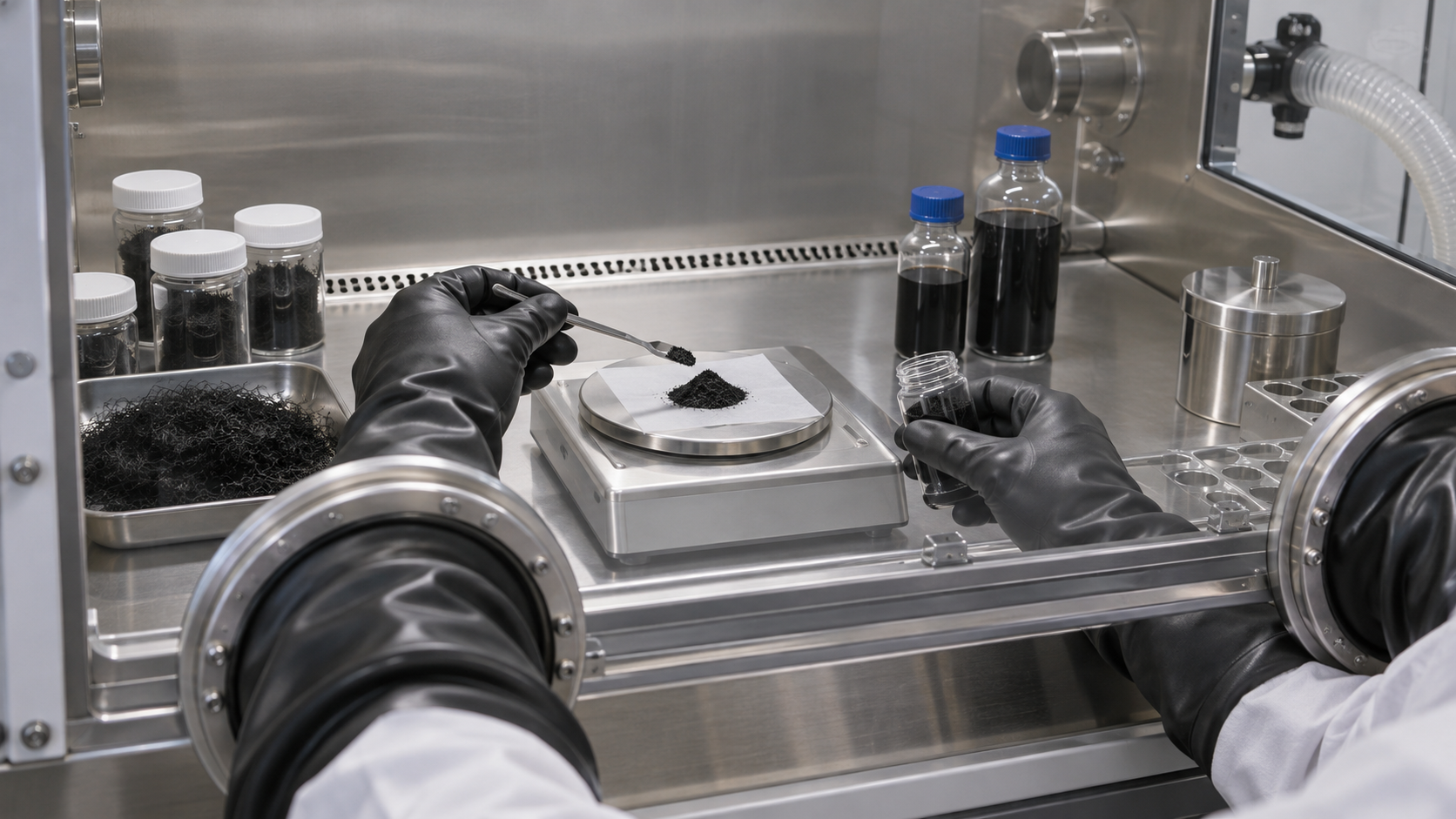
- What a carbon nanotube is (the short version)
- Structure — single and multi-walled, and metallic or semiconducting by rolling
- Our calculation: getting the diameter from the rolling
- Production — arc, laser, CVD, super-growth, floating catalyst
- Our calculation: setting stated values against geometry
- A materials engineer's view (1): read stated values by edition, date and method
- Separation and dispersion — sorting mixed tubes and loosening bundles
- Applications — batteries, composites, wiring and transistors by stage
- Safety — reading the public bodies' assessments as written
- A materials engineer's view (2): judge by form, dose and handling, not by "nano"
- What could not be confirmed / how this fits with other articles in the series
- How to read evaluations and standards
- Glossary
- Primary sources
- Claim-to-source audit
Sourced = a statement in a paper, standard, public document or product page (link given)
Our calculation = a figure this article derived, with the assumptions spelled out
Not yet confirmed = a plan or outlook with no confirmed record
Materials-design interpretations are marked separately as Commentary.
Manufacturers’ values are marked “manufacturer’s stated value”, with the method and date where known.
The safety sections report public bodies’ assessments as worded and are not advice on any particular product or handling.
Sensor uses (electrodes, FETs, functionalisation) were covered in our biosensor explainer on graphene and carbon nanotubes; this article is about the material itself.
1. What a carbon nanotube is (the short version)
A CNT is a sheet of graphene rolled seamlessly into a tube. In 1991 Iijima reported needle-like structures from arc-discharge carbon, made of coaxial tubes nested from two up to about 50 layers Sourced [Ref. 1]. In 1993 Iijima and Ichihashi reported single-shell tubes about 1 nm in diameter, and Bethune and co-workers reported tubes with walls one atomic layer thick and a diameter of about 1.2 nm from an arc with cobalt added Sourced [Ref. 2, 3].
- The rolling sets the electronic character: tight-binding calculations predicted that, depending on diameter and the degree of helical arrangement of the carbon hexagons, tubes range from metallic through narrow- and moderate-gap semiconducting Sourced [Ref. 9]. Another calculation put roughly one third as metals and two thirds as semiconductors Sourced [Ref. 10].
- The route sets the form: arc, laser, CVD, super-growth and floating catalyst differ in single or multi-wall, diameter, length, leftover metal catalyst, and whether you get a forest or a fibre (Chapter 4).
- Talk about safety by form: in IARC Monographs Volume 111 (2017), the International Agency for Research on Cancer rated MWCNT-7 as “possibly carcinogenic to humans (Group 2B)” and other multi-walled and single-walled CNTs as “not classifiable (Group 3)” Sourced [Ref. 24]. “Nano is dangerous” and “nano is safe” are both unsupported generalisations (Chapter 9).
The name “CNT” covers many different materials, differing in diameter, wall count, length, rolling, purity and how they clump. On a specification, look past the name to single or multi-wall, the distributions of diameter and length, the amount of metal catalyst and amorphous carbon, and a picture of the dispersed state. Even for one product from one maker, stated values change by edition and date (Chapter 6) (Commentary).
2. Structure — single and multi-walled, and metallic or semiconducting by rolling
A single-walled CNT (SWCNT) is one tube; a multi-walled CNT (MWCNT) is several nested tubes. The electronic behaviour of an SWCNT depends on how the sheet is rolled (its chirality, a pair of integers (n, m)). In 1992 Hamada and co-workers predicted that carbon microtubules would vary greatly, from metallic to semiconducting, with diameter and the degree of helical arrangement of the hexagons Sourced [Ref. 9]. Saito and co-workers calculated in the same year that about one third of single-layer tubes would be one-dimensional metals and the other two thirds one-dimensional semiconductors Sourced [Ref. 10].
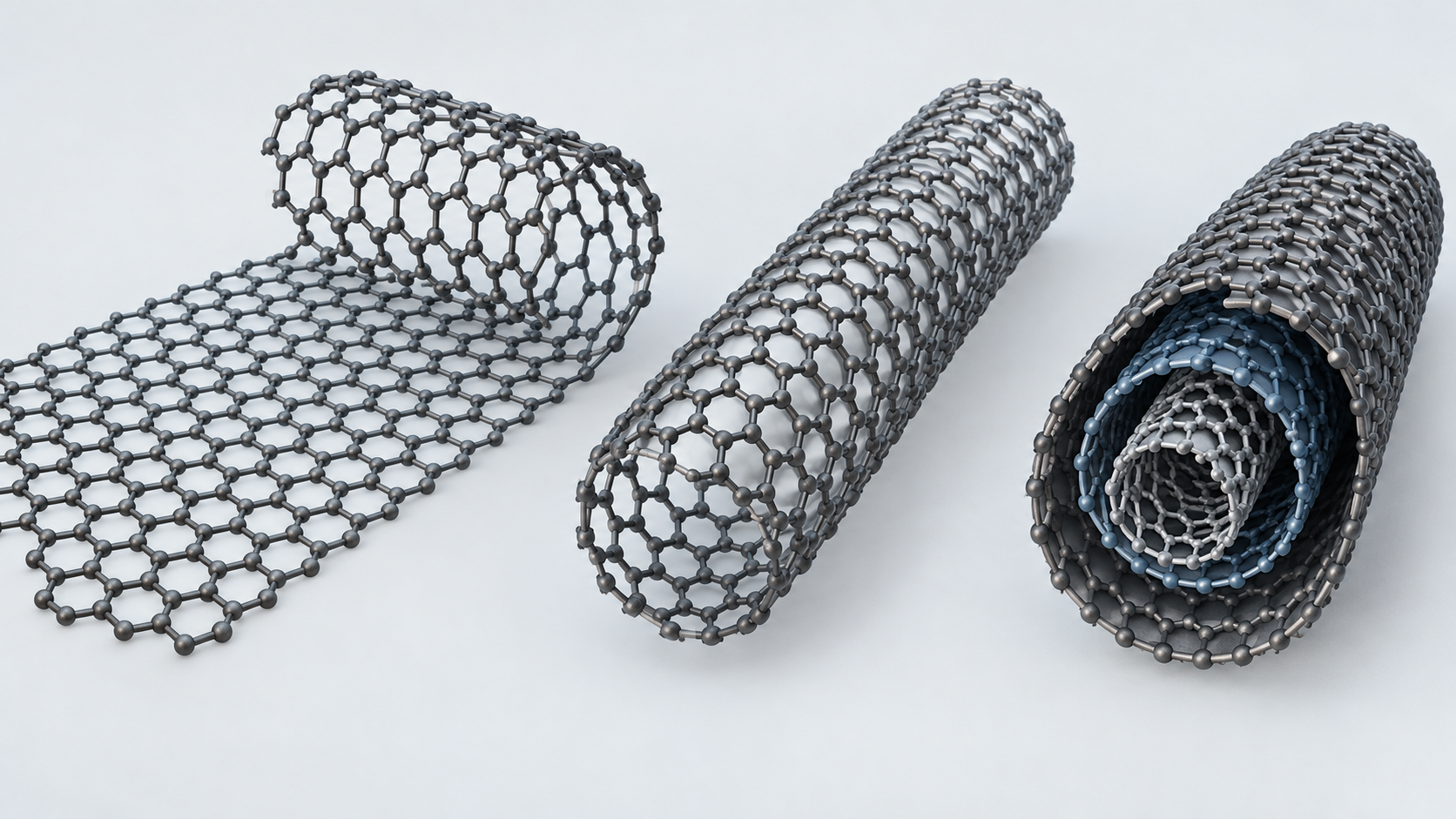
Shapes, colors and dimensions are illustrative. Consult the original schematic below for exact values and label correspondence.
View the original SVG schematic and exact annotations
Reading guide and original schematic labels: CNT structure and the electronic character set by rolling (concept) / Atom counts, diameters and lengths are not to scale / 1 Roll the sheet / 2 Single and multi-wall / 3 Rolling sets the character / Rolling direction (n, m) / Seamless tube / One tube = single-wall / SWCNT / cross-section (one) / MWCNT / cross-section (nested) / Iijima 1991: 2 to about 50 layers / Metal ~1/3 / Semiconductor ~2/3 / Estimate for single-layer tubes (Saito 1992) / Band gap also varies with diameter / (Hamada 1992) / As-grown tubes tend to be a mixture / Electronics needs sorting (Chapter 7) / * The sheet and tube on the left are illustrative; the hexagonal lattice and the (n, m) assignment are not drawn. / * The one-third and two-thirds figures are calculated estimates [Ref. 10], not the proportions in real products. / * Layer counts follow Iijima (1991) [Ref. 1]. Numbers of circles are schematic.
Mechanical numbers also depend on what was measured
As with graphene, figures for CNT strength change meaning with sample and method. In 1996 Treacy and co-workers estimated, from the amplitude of the thermal vibrations of isolated tubes in a transmission electron microscope, that Young’s moduli are in the terapascal range Sourced [Ref. 11]. In 2000 Yu and co-workers pulled 19 individual MWCNTs on a “nanostressing stage” inside a scanning electron microscope and reported a tensile strength of the outermost layer of 11 to 63 GPa and a Young’s modulus of the outermost layer of 270 to 950 GPa (the tubes failed by the outer layer sliding out, “sword-in-sheath”) Sourced [Ref. 12]. Even for one “CNT strength”, there is a spread depending on how it was measured (thermal vibration or tension) and on what sample (an isolated tube or the outer shell of a multi-walled one).
3. Our calculation: getting the diameter from the rolling
Let us check whether the formula for diameter from (n, m) agrees with a measured value in a paper Our calculation.
- Assumptions: graphene lattice constant a = √3 × 0.142 nm = 0.246 nm (the 0.142 nm carbon–carbon bond length is our assumption). Diameter d = a√(n² + nm + m²) ÷ π (a standard geometric relation; we have not confirmed it in a primary source).
- (10, 10): √(100 + 100 + 100) = √300 = 17.32. d = 0.246 × 17.32 ÷ 3.1416 = about 1.36 nm
- Thess and co-workers obtained, from X-ray scattering, a diameter of 13.8 ± 0.2 Å (1.38 ± 0.02 nm) for the single-wall tubes made by laser vaporisation, and say the energetics “strongly favor the metallic (10,10) tube” Sourced [Ref. 5]
- (6, 5) as a further example: √(36 + 30 + 25) = √91 = 9.54. d = 0.246 × 9.54 ÷ 3.1416 = about 0.75 nm
Assumptions and limits: the diameter formula is a standard geometric relation, but we have not checked a primary source for the formula itself. That the calculated 1.36 nm and the measured 1.38 nm agree only confirms that the formula and bond length are reasonable; it says nothing about the (n, m) distribution of any given sample.
4. Production — arc, laser, CVD, super-growth, floating catalyst
CNT routes differ in where the carbon comes from and where the catalyst sits. The older routes (arc and laser) established that single-wall tubes exist; today’s industrial production is centred on CVD-type routes (this article’s own grouping).
| Route | Reported values and statements (with conditions) | Issues on the materials side (source or commentary) |
|---|---|---|
| Arc discharge | Iijima (1991): arc-discharge evaporation grew nested tubes on the cathode, from 2 up to about 50 layers Sourced [Ref. 1]. Iijima and Ichihashi (1993): single-shell tubes about 1 nm in diameter grew in the gas phase (multi-shell tubes formed on the cathode) Sourced [Ref. 2]. Bethune et al. (1993): co-vaporising carbon and cobalt gave tubes with walls one atomic layer thick and a diameter of about 1.2 nm Sourced [Ref. 3]. Journet et al. (1997): the cheaper and easier arc technique could yield large quantities of single-wall tubes with characteristics similar to those from laser ablation (for which yields of 70 to 90% are cited) Sourced [Ref. 4] | Single- and multi-wall tubes can coexist. Metal catalyst (Co and so on) remains (Commentary) |
| Laser vaporisation | Thess et al. (1996): laser vaporisation of a carbon-nickel-cobalt mixture at 1200 °C gave yields above 70%. The diameter is nearly uniform and the tubes self-organise into “ropes” of 100 to 500 tubes on a triangular lattice. Diameter about 13.8 Å; single-rope resistivity below 10-4 Ω·cm at 300 K Sourced [Ref. 5] | Laboratory-scale apparatus. Tubes come in bundles, so a loosening step is needed (Commentary) |
| CVD: super-growth | Hata et al. (2004): water enhanced catalyst activity and lifetime, giving a dense, vertically aligned “forest” up to 2.5 mm high, easily separated from the catalyst, with carbon purity above 99.98% Sourced [Ref. 6] | The forest height is not the tube length; processing shortens tubes (Commentary). How it was industrialised: Chapter 6 |
| CVD: floating catalyst, direct spinning | Li et al. (2004): fibres and ribbons were spun directly from the CVD reaction zone of a furnace using a liquid carbon source and iron nanocatalyst, withdrawn continuously with a rotating spindle Sourced [Ref. 7] | Fibre performance depends on tube alignment, bundling and length (Commentary) |
| Bulk growth then wet spinning | Behabtu et al. (2013): bulk-grown CNTs were wet-spun, as in industrial fibre production, into fibres reported to combine the specific strength, stiffness and thermal conductivity of carbon fibres with the specific electrical conductivity of metals Sourced [Ref. 8] | A research report. Guaranteed values for production goods not confirmed |
As stated in each paper’s abstract. Conditions (catalyst, temperature, feedstock, method) differ, so the table does not rank the routes.
5. Our calculation: setting stated values against geometry
Using the manufacturer’s stated values for Zeon’s super-growth CNT, ZEONANO SG101, let us compare them with what geometry allows. On its English page Zeon gives a specific surface area above 1,100 m²/g, a forest length of 300 to 500 µm, an average diameter of 3 to 5 nm, a carbon purity of at least 99% and metal impurities below 500 ppm Sourced [Ref. 26] (the page states no measurement methods).
- A guide to specific surface area: the outer surface of a closed single-wall tube equals one side of graphene, about 1,314 m²/g (from our graphene explainer’s calculation: 0.142 nm bond length, 1.994 × 10⁻²³ g per carbon atom, 0.0262 nm² per atom). The stated “above 1,100 m²/g” is at least about 84% of that. The “800 or more” in METI’s June 2022 sheet would be at least about 61%.
- Forest length ÷ diameter: 300 µm ÷ 5 nm = 6 × 10⁴; 500 µm ÷ 3 nm = about 1.7 × 10⁵
Assumptions and limits: the surface-area guide idealises closed tubes, no bundling and only the outer face being measured (real values change with bundles, open ends and inner surfaces). BET values depend on adsorption conditions (the relative-pressure range), which the manufacturer does not give. The forest length is the height of the grown bundle, not the length of tubes after dispersion or compounding (processing shortens them; Commentary). So 6 × 10⁴ to 1.7 × 10⁵ is a ratio of as-grown dimensions, not “the aspect ratio of the material”.
6. A materials engineer’s view (1): read stated values by edition, date and method
For ZEONANO SG101 the specific surface area is “more than 1,100 m²/g” on Zeon’s English page as checked in October 2026, but “800 or more” (BET method) in the nanomaterial information sheet that METI publishes (Zeon Corporation of Japan, as of June 2022) Sourced [Ref. 26, 27]. The same sheet gives a carbon content of 99% or more (TGA), a powder form with fibrous primary particles, and a product particle size of aggregates of a few micrometres to a few millimetres Sourced [Ref. 27]. This is not a question of which is “right”. Stated values vary with whether they are a specification (a guaranteed floor), a typical value, and the date or edition of the specification (the following is Commentary).
- Floor or typical: “min”, “more than” and “or more” are the language of guaranteed values and differ from typical values. For an acceptance specification, check which you are given.
- Method: specific surface area is by BET (the value moves with the adsorbate and the relative-pressure range); carbon purity is by TGA (which looks at what burns away and what is left, namely metal oxide). A TGA carbon content of 99% or more is not “99% SWCNT”; it can include other carbon such as amorphous carbon (Commentary).
- A maker’s “G/D ratio”: OCSiAl says of its TUBALL that “G/D > 90” and impurities are “< 1%” Sourced (manufacturer’s stated value; the page gives no conditions such as excitation wavelength) [Ref. 28]. The Raman G/D ratio changes with excitation wavelength (see the Raman chapter of our graphene explainer), so ask for conditions to be stated.
- Sense of scale: METI’s sheet gives the member companies’ total production in fiscal 2021 as “172 t to 222 t” (as surveyed by NBCI) Sourced [Ref. 27], in tonnes. In an April 2026 news item OCSiAl says it will add synthesis units and aims at a total capacity of 1,000 tonnes Not yet confirmed (a company plan) [Ref. 29].
7. Separation and dispersion — sorting mixed tubes and loosening bundles
As-grown SWCNTs are a mixture of diameters, chiralities and metallic character, and they come in bundles. For electronic and optical uses they have to be sorted into metallic and semiconducting tubes, and ideally into a single (n, m).
Arnold et al. used density-gradient ultracentrifugation to separate SWCNTs with more than 97% of tubes within a 0.02 nm diameter range, and obtained large amounts of nearly a single electronic type (the same paper as in the biosensor explainer) Sourced [Ref. 13]. In 2003 Zheng et al. dispersed SWCNTs in water with single-stranded DNA and sonication and showed that ion-exchange chromatography could split them into fractions of different electronic structure Sourced [Ref. 14]. In 2009 Tu et al. reported that DNA sequences made of repeats of one purine followed by one or more pyrimidines could purify specific structures from a mixture Sourced [Ref. 15]. In 2011 Liu et al. separated 13 different (n, m) species on a large scale with one surfactant and vertically connected gel columns, the metallic SWCNTs being collected last as unbound tubes Sourced [Ref. 16]. In 2007 Nish et al. reported that particular aromatic polymers disperse certain SWCNT species selectively, giving suspensions with up to about 60% relative concentration of a single species and fluorescence quantum yields of up to 1.5% Sourced [Ref. 17].
Industrially, the form used as a battery conductive additive is a dispersion of SWCNTs in a solvent such as NMP. In April 2026 OCSiAl announced NMP-based ultrafine dispersions, dispersions for Li-CMC binders and dispersions for solid-state batteries Sourced (the maker’s announcement; the news item gives no specific content or performance values) [Ref. 29]. The quality of dispersion (how far bundles are loosened, and whether tubes are broken or shortened) bears directly on how easily a conductive network forms, but we could not confirm a primary source with numbers on this point within the scope of this article.
8. Applications — batteries, composites, wiring and transistors by stage
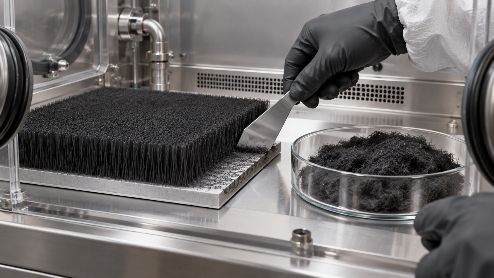
For each application, what has been reported is separated from the stage we could confirm. Being sold as a product and being adopted in an end product are different things. We could not confirm official material for the latter (Chapter 11).
| Application | Report or statement (with conditions) | Stage |
|---|---|---|
| Conductive additive in batteries | A review notes that using CNTs as a conductive additive at a lower weight loading than conventional carbon black or graphite can establish an electrical percolation network more effectively Sourced [Ref. 18]. Zeon explains that SG101’s long tubes give a low percolation threshold and binder-free self-supporting films, and that little residual metal catalyst means no reaction with electrolyte Sourced (the maker’s explanation) [Ref. 26]. OCSiAl says its TUBALL is effective even at an ultra-low 0.01%, and is used at 0.03 to 0.1% depending on the application Sourced (manufacturer’s stated value; no measurement conditions given) [Ref. 28] | Makers list dispersions and powder as products. Official material on adoption in a particular cell or vehicle not confirmed |
| Composites and fibres | CNT and graphene composites have been studied for about two decades, but issues remain from load transfer, interface, dispersion and viscosity Sourced [Ref. 19]. Fibres wet-spun from bulk-grown CNTs are reported to combine the specific strength, stiffness and thermal conductivity of carbon fibre with the specific electrical conductivity of metals Sourced [Ref. 8] | Research reports. Guaranteed values for production goods not confirmed |
| Wiring and conductors | A CNT–copper composite had a conductivity of 2.3 to 4.7 × 10⁵ S/cm (copper: 5.8 × 10⁵ S/cm) and an ampacity of 6 × 10⁸ A/cm², about 100 times that of copper Sourced [Ref. 20] | Research report (calculation below) |
| Transistors | A computer built entirely from carbon-nanotube field-effect transistors (178 transistors, each with 10 to 200 CNTs, running a simple operating system with multitasking) Sourced [Ref. 21]. A 16-bit RISC-V microprocessor with more than 14,000 complementary CNFETs. The authors say that the inability to perfectly control nanoscale defects and variability had precluded very-large-scale integration, and propose a manufacturing methodology to overcome it Sourced [Ref. 22] | Demonstration (research). Volume production not confirmed Not yet confirmed |
Our calculation
- 2.3 × 10⁵ ÷ 5.8 × 105 = about 40%; 4.7 × 10⁵ ÷ 5.8 × 105 = about 81%
- The ampacity of 6 × 10⁸ A/cm² is “about 100 times” that of copper; working back from the paper’s wording gives copper at about 6 × 10⁶ A/cm²
Assumptions and limits: the conductivity and ampacity are from the paper’s abstract. The copper figure is our back-calculation from “100 times” and not a copper measurement given in the paper. The samples are laboratory reports on tiny conductors, not the performance of bulk wire. Conductivity per volume and per mass are different measures (we have not confirmed a per-mass value).
9. Safety — reading the public bodies’ assessments as written
The safety of CNTs can be called neither “dangerous because nano” nor “safe”. Results differ with form (length, diameter, rigidity), wall count, residual metal catalyst, state of agglomeration and route of exposure, so public bodies assess by type.
- IARC (Volume 111, 2017): evidence of carcinogenicity in humans is inadequate. In animals the evidence is sufficient for MWCNT-7, limited for two types of multi-walled tube with dimensions similar to MWCNT-7, and inadequate for other multi-walled tubes and for single-walled tubes. The overall evaluation is that MWCNT-7 is “possibly carcinogenic to humans (Group 2B)”, while other multi-walled and single-walled CNTs are “not classifiable as to their carcinogenicity to humans (Group 3)” Sourced [Ref. 24]. On mechanisms, IARC notes lung inflammation, granuloma formation and fibrosis in rats and mice exposed to single-walled, double-walled or multi-walled CNTs, and pleural inflammation or proliferation with three types of multi-walled CNT (MWCNT-7, MWCNT-N and Helix), and says that because of the heterogeneity of CNTs and the limited long-term studies, significant data gaps remain Sourced [Ref. 24].
- An MWCNT-7 inhalation study: Kasai et al. exposed male and female F344 rats to a fibrous straight type of MWCNT (MWNT-7) by whole-body inhalation for 104 weeks at 0, 0.02, 0.2 and 2 mg/m³. Lung carcinomas, mainly bronchiolo-alveolar carcinoma, increased significantly in males at 0.2 and 2 mg/m³ and in females at 2 mg/m³, and no pleural mesothelioma was observed Sourced [Ref. 23].
- NIOSH (U.S. National Institute for Occupational Safety and Health, April 2013): from a quantitative risk assessment on animal dose-response data, NIOSH proposes a recommended exposure limit (REL) of 1 µg/m³ of respirable elemental carbon as an 8-hour time-weighted average. It says that it is not known whether similar effects occur in humans, but that the animal results indicate the need to minimise worker exposure Sourced [Ref. 25] (a REL is a recommendation, not a legal exposure limit; Commentary).
- A company’s statement: in the METI sheet, Zeon of Japan states, for its SG-CNT, that an intraperitoneal study in rats found no carcinogenicity in mesothelial cells, a 13-week inhalation study found no histopathological change in lung or other organs, and a gene-mutation test with mouse lymphoma cells found no genotoxicity, with details in its safety data sheet Sourced (the company’s statement; we have not seen the test data itself) [Ref. 27].
We could not confirm the treatment of CNTs under Japanese occupational safety law and similar rules in public documents, so we do not state it here. Regulations such as the EU REACH nanoform provisions are covered in our explainer on the definition and regulation of nanomaterials.
10. A materials engineer’s view (2): judge by form, dose and handling, not by “nano”
- Look by type: IARC put only MWCNT-7 in 2B and the rest in 3, so “CNT” cannot be treated as one thing. Confirm from the distributions of diameter and length whether what you buy is a long, straight multi-wall like MWCNT-7, a short, curved multi-wall or a single-wall (Commentary).
- Do not read “Group 3” as safe: it means the evidence is inadequate, the flip side of few long-term studies (IARC itself says significant data gaps remain).
- Handling powders: NIOSH says that airborne CNTs behave as classical aerosols, so standard exposure controls such as source enclosure and local exhaust ventilation appear feasible Sourced [Ref. 25]. Weighing and mixing powder are where exposure on the materials side mainly arises (Commentary). Zeon’s entry in the METI sheet likewise lists work in a clean room, exhaust through HEPA filters, protective equipment and storage in sealed containers Sourced [Ref. 27].
- Once in dispersion: airborne dust is less likely, but drying, grinding and machining can bring dust back (Commentary). Specific safety measures follow the safety data sheet and the competent authority’s guidance; this article gives no advice.
11. What could not be confirmed / how this fits with other articles in the series
(1) What we could not confirm within the scope of this article
- Official material on a particular volume-production cell or vehicle that uses CNTs as a conductive additive, and the detailed measurement conditions (BET, G/D ratio) behind makers’ stated values, could not be confirmed Not yet confirmed.
- Primary sources for guaranteed values in production composites, fibres and wiring, and for the price or production cost of CNTs, could not be confirmed.
- Volume production of CNT transistors could not be confirmed. The values of Hills et al. are laboratory demonstrations Not yet confirmed.
- Specific regulation of CNTs in Japan, the EU and the United States (their legal status) has not been confirmed from official documents.
- We did not confirm a primary source quantifying dispersion quality (how bundles are loosened, how tubes shorten), nor the numbers and content of ISO/TC 229 technical specifications for CNT characterisation, on the official pages, so they are not stated. The terminology standard (ISO/TS 80004-3) is mentioned in our biosensor explainer on graphene and carbon nanotubes.
(2) How this fits with other articles in the series
Graphene production, quality and transfer are covered in our graphene explainer. For electrodes, FETs and functionalisation when CNTs and graphene are used in sensors, see our biosensor explainer on graphene and carbon nanotubes; for dispersion in polymers and composites, see our explainer on polymer blends and fillers; and for the area around battery conductive additives, see our explainers on silicon anodes and nanostructured electrodes and on supercapacitors.
- A CNT is not a single material. Single or multi-wall, the rolling (an estimated one third metallic and two thirds semiconducting) and the production route set diameter, length and purity Sourced
- Stated values change with edition and date. The specific surface area of the same ZEONANO SG101 is “800 or more” (a June 2022 sheet) and “more than 1,100” (the current page) Sourced
- Separation is research-scale. Separation of 13 (n, m) species and dispersion of up to about 60% of one species have been reported Sourced
- Applications are at different stages. Dispersions are listed as products for conductive additives, and transistors have been demonstrated to more than 14,000 devices; composites and wiring are at the research stage Sourced
- Safety is assessed by type. IARC placed MWCNT-7 in 2B and other multi-walled and single-walled CNTs in 3 Sourced
- The NIOSH REL is 1 µg/m³ (respirable elemental carbon, 8 hours). It is a recommendation, not a legal exposure limit Sourced
12. How to read evaluations and standards
Before comparing which number is larger, align the basis of comparison in the following order. This is an editorial reading checklist, not a set of test conditions or acceptance limits prescribed by a standard.
- 1. What was measured?
- conductivity, tensile strength and electrode capacity. Check the units and whether the result describes a material, component or complete system.
- 2. Under which conditions?
- individual tube versus assembly, dispersion, alignment, loading and specimen dimensions. Treat results under different conditions as separate results before comparing them.
- 3. The comparison trap
- Do not transfer a single-tube result to a composite or a manufactured electrode.
- 4. What does the standard cover?
- Check the identifier, title, edition and scope in the issuing body’s material. Distinguish test methods, safety, interoperability and management requirements. Naming a standard alone does not establish that a test, conformity assessment or certification has been completed.
Keep a comparison note containing the object, units, conditions, sample count and variation, comparator, standard edition and unresolved points. Do not invent numerical conditions or acceptance limits from a public abstract of a standard.
13. Glossary
- Single-walled CNT (SWCNT)
- A graphene sheet rolled into one tube. Diameter from about 1 nm to a few nm.
- Multi-walled CNT (MWCNT)
- Several tubes nested one inside another. From two layers up to a few dozen.
- Chirality ((n, m))
- A pair of integers giving the rolling direction and thickness of the tube. It decides the electronic character (metal or semiconductor).
- Arc-discharge method
- Vaporising carbon with an arc between graphite electrodes and condensing it into tubes.
- Laser vaporisation
- Vaporising a metal-containing carbon target with a laser. Single-wall “ropes” result.
- CVD
- Chemical vapour deposition. Tubes grow from a carbon-containing gas over a catalyst.
- Super-growth method
- Water prolongs the catalyst life and grows a long vertically aligned forest of single-wall CNTs (discovered at AIST).
- Forest
- An array of CNTs grown standing vertically on a substrate. Its height is a guide to tube length.
- Floating-catalyst CVD
- The catalyst is not fixed to a substrate but reacts in the gas phase of the furnace. Used for direct spinning of fibres.
- Density-gradient ultracentrifugation
- Sorting tubes by electronic structure through differences in buoyant density caused by surfactants.
- BET specific surface area
- Specific surface area from nitrogen adsorption. The value moves with conditions such as the relative-pressure range.
- TGA
- Thermogravimetric analysis. Mass change on heating shows the carbon content and what is left (metal oxide).
- G/D ratio
- The ratio of the Raman G and D band intensities. A guide to crystallinity, but it changes with excitation wavelength.
- Percolation threshold
- The loading at which a conductive network connects throughout and conductivity jumps. Lower for slender tubes.
- Ampacity
- The maximum current density a conductor can carry without failing.
- IARC Group 2B / Group 3
- 2B: possibly carcinogenic to humans. 3: not classifiable as to carcinogenicity to humans. Group 3 is not a statement of safety.
- REL (recommended exposure limit)
- An exposure limit recommended by NIOSH for workplaces. It is not a legal exposure limit.
14. Primary sources
- Iijima S “Helical microtubules of graphitic carbon”, Nature 1991;354:56–58 — doi.org/10.1038/354056a0
- Iijima S, Ichihashi T “Single-shell carbon nanotubes of 1-nm diameter”, Nature 1993;363:603–605 — doi.org/10.1038/363603a0
- Bethune DS et al. “Cobalt-catalysed growth of carbon nanotubes with single-atomic-layer walls”, Nature 1993;363:605–607 — doi.org/10.1038/363605a0
- Journet C et al. “Large-scale production of single-walled carbon nanotubes by the electric-arc technique”, Nature 1997;388:756–758 — doi.org/10.1038/41972
- Thess A et al. “Crystalline Ropes of Metallic Carbon Nanotubes”, Science 1996;273:483–487 — doi.org/10.1126/science.273.5274.483
- Hata K et al. “Water-Assisted Highly Efficient Synthesis of Impurity-Free Single-Walled Carbon Nanotubes”, Science 2004;306:1362–1364 — doi.org/10.1126/science.1104962
- Li Y-L, Kinloch IA, Windle AH “Direct Spinning of Carbon Nanotube Fibers from Chemical Vapor Deposition Synthesis”, Science 2004;304:276–278 — doi.org/10.1126/science.1094982
- Behabtu N et al. “Strong, Light, Multifunctional Fibers of Carbon Nanotubes with Ultrahigh Conductivity”, Science 2013;339:182–186 — doi.org/10.1126/science.1228061
- Hamada N, Sawada S, Oshiyama A “New one-dimensional conductors: Graphitic microtubules”, Phys Rev Lett 1992;68:1579–1581 — doi.org/10.1103/PhysRevLett.68.1579
- Saito R, Fujita M, Dresselhaus G, Dresselhaus MS “Electronic structure of chiral graphene tubules”, Appl Phys Lett 1992;60:2204–2206 — doi.org/10.1063/1.107080
- Treacy MMJ, Ebbesen TW, Gibson JM “Exceptionally high Young’s modulus observed for individual carbon nanotubes”, Nature 1996;381:678–680 — doi.org/10.1038/381678a0
- Yu M-F et al. “Strength and Breaking Mechanism of Multiwalled Carbon Nanotubes Under Tensile Load”, Science 2000;287:637–640 — doi.org/10.1126/science.287.5453.637
- Arnold MS, Green AA, Hulvat JF, Stupp SI, Hersam MC “Sorting carbon nanotubes by electronic structure using density differentiation”, Nat Nanotechnol 2006;1:60–65 — doi.org/10.1038/nnano.2006.52
- Zheng M et al. “DNA-assisted dispersion and separation of carbon nanotubes”, Nat Mater 2003;2:338–342 — doi.org/10.1038/nmat877
- Tu X et al. “DNA sequence motifs for structure-specific recognition and separation of carbon nanotubes”, Nature 2009;460:250–253 — doi.org/10.1038/nature08116
- Liu H et al. “Large-scale single-chirality separation of single-wall carbon nanotubes by simple gel chromatography”, Nat Commun 2011;2:309 — doi.org/10.1038/ncomms1313
- Nish A et al. “Highly selective dispersion of single-walled carbon nanotubes using aromatic polymers”, Nat Nanotechnol 2007;2:640–646 — doi.org/10.1038/nnano.2007.290
- Landi BJ et al. “Carbon nanotubes for lithium ion batteries”, Energy Environ Sci 2009;2:638–654 (review) — doi.org/10.1039/b904116h
- Kinloch IA et al. “Composites with carbon nanotubes and graphene: An outlook”, Science 2018;362:547–553 — doi.org/10.1126/science.aat7439
- Subramaniam C et al. “One hundred fold increase in current carrying capacity in a carbon nanotube–copper composite”, Nat Commun 2013;4:2202 — doi.org/10.1038/ncomms3202
- Shulaker MM et al. “Carbon nanotube computer”, Nature 2013;501:526–530 — doi.org/10.1038/nature12502
- Hills G et al. “Modern microprocessor built from complementary carbon nanotube transistors”, Nature 2019;572:595–602 — doi.org/10.1038/s41586-019-1493-8
- Kasai T et al. “Lung carcinogenicity of inhaled multi-walled carbon nanotube in rats”, Part Fibre Toxicol 2016;13:53 — doi.org/10.1186/s12989-016-0164-2
- IARC “Carbon nanotubes”, IARC Monographs on the Evaluation of Carcinogenic Risks to Humans, Volume 111 (Some Nanomaterials and Some Fibres), 2017, relevant chapter (PDF); section 6 “Evaluation” is cited — publications.iarc.who.int
- NIOSH “Occupational Exposure to Carbon Nanotubes and Nanofibers”, Current Intelligence Bulletin 65, DHHS (NIOSH) Publication No. 2013-145, April 2013 (PDF) — cdc.gov
- Zeon Corporation “Carbon Nanotube: ZEONANO SG101”, English product page (checked October 2026); manufacturer’s stated values — zeon.co.jp
- Ministry of Economy, Trade and Industry (METI), Japan “Nanomaterial information sheet: carbon nanotubes (Zeon Corporation)”, as of June 2022 (PDF, in Japanese) — meti.go.jp
- OCSiAl “Graphene Nanotubes For Industrial Applications”, product overview page (checked October 2026); manufacturer’s stated values — ocsial.com
- OCSiAl “OCSiAl Introduces New SWCNT Products for High-Performance Electrodes and Emerging Battery Chemistries”, news item, 28 April 2026 — ocsial.com
15. Claim-to-source audit
| Claim in the text | Basis | Label |
|---|---|---|
| 1991: needle-like structures of coaxial tubes nested from 2 up to about 50 layers, from arc-discharge carbon | Iijima 1991 (Nature)[Ref. 1] https://doi.org/10.1038/354056a0 | Sourced |
| 1993: single-shell tubes about 1 nm in diameter grown in the gas phase (multi-shell on the cathode); tubes with single-atomic-layer walls and a diameter of about 1.2 nm from an arc with cobalt | Iijima and Ichihashi 1993 (Nature)[Ref. 2] https://doi.org/10.1038/363603a0; Bethune et al. 1993 (Nature)[Ref. 3] https://doi.org/10.1038/363605a0 | Sourced |
| The arc technique can give large quantities of single-wall tubes similar to those from laser ablation (yields of 70 to 90%) | Journet et al. 1997 (Nature)[Ref. 4] https://doi.org/10.1038/41972 | Sourced |
| Laser vaporisation (1200 °C): yield above 70%, ropes of 100 to 500 tubes, diameter 13.8 ± 0.2 Å, rope resistivity below 10-4 Ω·cm at 300 K, the metallic (10,10) tube favoured | Thess et al. 1996 (Science)[Ref. 5] https://doi.org/10.1126/science.273.5274.483 | Sourced |
| Super-growth: forest up to 2.5 mm high, carbon purity above 99.98%, water raises catalyst activity and lifetime | Hata et al. 2004 (Science)[Ref. 6] https://doi.org/10.1126/science.1104962 | Sourced |
| Floating-catalyst CVD: fibres and ribbons spun directly from the reaction zone with a liquid carbon source and iron nanocatalyst | Li et al. 2004 (Science)[Ref. 7] https://doi.org/10.1126/science.1094982 | Sourced |
| Wet-spun fibres from bulk-grown CNTs combine the specific strength, stiffness and thermal conductivity of carbon fibres with the specific conductivity of metals | Behabtu et al. 2013 (Science)[Ref. 8] https://doi.org/10.1126/science.1228061 | Sourced |
| Metallic to semiconducting depending on diameter and helical arrangement; about one third of single-layer tubes metallic and two thirds semiconducting | Hamada et al. 1992 (PRL)[Ref. 9] https://doi.org/10.1103/PhysRevLett.68.1579; Saito et al. 1992 (Appl Phys Lett)[Ref. 10] https://doi.org/10.1063/1.107080 | Sourced |
| Young’s modulus of isolated tubes in the terapascal range (estimated from thermal-vibration amplitude) | Treacy et al. 1996 (Nature)[Ref. 11] https://doi.org/10.1038/381678a0 | Sourced |
| Tensile tests on 19 MWCNTs: outer-layer strength 11 to 63 GPa, Young’s modulus 270 to 950 GPa, sword-in-sheath failure | Yu et al. 2000 (Science)[Ref. 12] https://doi.org/10.1126/science.287.5453.637 | Sourced |
| Density-gradient separation: over 97% within a 0.02 nm diameter range, nearly one electronic type | Arnold et al. 2006 (Nat Nanotechnol)[Ref. 13] https://doi.org/10.1038/nnano.2006.52 | Sourced |
| DNA dispersion of SWCNTs with ion-exchange fractions by electronic structure; DNA sequences that purify particular structures | Zheng et al. 2003 (Nat Mater)[Ref. 14] https://doi.org/10.1038/nmat877; Tu et al. 2009 (Nature)[Ref. 15] https://doi.org/10.1038/nature08116 | Sourced |
| Gel chromatography separating 13 (n, m) species on a large scale; metallic tubes recovered as unbound | Liu et al. 2011 (Nat Commun)[Ref. 16] https://doi.org/10.1038/ncomms1313 | Sourced |
| Aromatic polymers: up to about 60% relative concentration of a single species; fluorescence quantum yield up to 1.5% | Nish et al. 2007 (Nat Nanotechnol)[Ref. 17] https://doi.org/10.1038/nnano.2007.290 | Sourced |
| Zeon’s stated values: specific surface area above 1,100 m²/g, forest length 300 to 500 µm, average diameter 3 to 5 nm, carbon purity at least 99%, metal impurities below 500 ppm; the features claimed (low percolation threshold, binder-free self-supporting film, no reaction with electrolyte). No measurement methods given | Manufacturer’s stated values. Zeon product page[Ref. 26] https://www.zeon.co.jp/en/business/enterprise/nanotube/carbonnanotube/ | Sourced |
| METI sheet (Zeon, as of June 2022): specific surface area 800 or more (BET), carbon content 99% or more (TGA), aggregates of a few µm to a few mm, powder with fibrous primary particles, fiscal 2021 total production of member companies 172 to 222 t (as surveyed by NBCI) | METI nanomaterial information sheet[Ref. 27] https://www.meti.go.jp/policy/chemical_management/files/nanomaterial/2022nanojouhoushuushuu/CNT3_2022.pdf | Sourced |
| OCSiAl’s stated values: G/D above 90, impurities below 1%, effective at 0.01%, used at 0.03 to 0.1% by application. No measurement conditions given | Manufacturer’s stated values. OCSiAl product page[Ref. 28] https://ocsial.com/nanotubes/ | Sourced |
| OCSiAl (April 2026): NMP-based dispersions, dispersions for Li-CMC binders and for solid-state batteries; plan to expand synthesis units toward 1,000 t of capacity | A company announcement and plan (not yet confirmed). OCSiAl news (April 2026)[Ref. 29] https://ocsial.com/news/ocsial-introduces-new-swcnt-products-for-high-performance-electrodes-and-emerging-battery-chemistries/ | Sourced |
| Using CNTs at a lower weight loading than conventional carbons establishes a percolation network more effectively (review) | Landi et al. 2009 (Energy Environ Sci)[Ref. 18] https://doi.org/10.1039/b904116h | Sourced |
| Issues for CNT and graphene composites (load transfer, interface, dispersion, viscosity) | Kinloch et al. 2018 (Science)[Ref. 19] https://doi.org/10.1126/science.aat7439 | Sourced |
| CNT–copper composite: conductivity 2.3 to 4.7 × 10⁵ S/cm (copper 5.8 × 10⁵), ampacity 6 × 10⁸ A/cm² (about 100 times copper) | Subramaniam et al. 2013 (Nat Commun)[Ref. 20] https://doi.org/10.1038/ncomms3202 | Sourced |
| A CNT computer of 178 transistors, each with 10 to 200 CNTs; a 16-bit RISC-V microprocessor with more than 14,000 complementary CNFETs | Shulaker et al. 2013 (Nature)[Ref. 21] https://doi.org/10.1038/nature12502; Hills et al. 2019 (Nature)[Ref. 22] https://doi.org/10.1038/s41586-019-1493-8 | Sourced |
| The IARC evaluation: inadequate evidence in humans; in animals sufficient for MWCNT-7, limited for two similar-dimension multi-walled types, inadequate for other multi-walled and for single-walled; overall MWCNT-7 Group 2B, other multi-walled and single-walled Group 3; mechanisms (lung inflammation, granuloma, fibrosis, pleural inflammation) and data gaps | IARC Monographs Vol. 111[Ref. 24] https://publications.iarc.who.int/download/mono111-01.pdf | Sourced |
| A 104-week whole-body inhalation study of MWNT-7 (0, 0.02, 0.2, 2 mg/m³, F344 rats): lung carcinoma increased in males at 0.2 and 2 and in females at 2 mg/m³; no pleural mesothelioma | Kasai et al. 2016 (Part Fibre Toxicol)[Ref. 23] https://doi.org/10.1186/s12989-016-0164-2 | Sourced |
| NIOSH CIB 65 (April 2013): REL of 1 µg/m³ respirable elemental carbon, 8-hour TWA; effects in humans unknown; standard exposure controls appear feasible | NIOSH CIB 65[Ref. 25] https://www.cdc.gov/niosh/docs/2013-145/pdfs/2013-145.pdf | Sourced |
| Zeon’s statements: no mesothelial carcinogenicity on intraperitoneal dosing in rats, no histopathological change in a 13-week inhalation study, no genotoxicity in a gene-mutation test; clean room, HEPA exhaust, protective equipment, sealed storage | The company’s statement; the test data were not seen. METI nanomaterial information sheet[Ref. 27] https://www.meti.go.jp/policy/chemical_management/files/nanomaterial/2022nanojouhoushuushuu/CNT3_2022.pdf | Sourced |
| Diameter of (10, 10) about 1.36 nm (lattice constant 0.246 nm = √3 × 0.142 nm), (6, 5) about 0.75 nm, 84% and 61% of the guide of about 1,314 m²/g, forest length ÷ diameter of 6 × 10⁴ to 1.7 × 10⁵, and 40 to 81% for the CNT–copper conductivity | Our calculation. The bond length, the diameter formula and the idealisation (closed tubes, outer face only, no bundles) are our assumptions. Forest length is not the length of tubes after processing. | Our calculation |
| A particular volume-production cell or vehicle, the measurement conditions behind makers’ values, guaranteed values for production goods, prices, volume production of transistors, specific national regulation, primary sources quantifying dispersion quality, and the ISO/TC 229 CNT technical specifications | No official material could be confirmed within the scope of this article, so none is stated (Commentary). | Not yet confirmed |
| Reading stated values by edition, date and method; TGA carbon content versus SWCNT content; reading Group 3 as not safe; judging by type with controls for powders; the groupings of routes, application stages and separation methods | This article’s own organisation and commentary based on the published material; not views stated by the authors or institutions. | Commentary |
| Figs. 1, 2, 4, 6 and 7 are explanatory drawings; Fig. 3 is drawn with our calculation; the hero image and Fig. 5 are AI-generated | Our note. | Commentary |
Last updated 9 October 2026. Sources are limited to primary material (peer-reviewed papers, IARC and NIOSH documents, a METI sheet and manufacturers’ official pages). Because the article includes materials-design interpretations, those are marked as Commentary and kept separate from sourced fact. Adoption in a particular volume-production cell or vehicle, the measurement conditions behind makers’ values, guaranteed values for production goods, prices, volume production of transistors, specific national regulation and primary sources quantifying dispersion quality are not stated because no primary source could be confirmed. Manufacturers’ values (Zeon, OCSiAl) are stated values without measurement methods or conditions. As Chapter 6 shows, stated values change with edition and date. The safety sections introduce public bodies’ assessments and are not advice on any particular handling. All figures are explanatory concept graphics. Figs. 1 to 4, 6 and 7 are vector drawings (Fig. 3 includes our calculation); the hero image and Fig. 5 are AI-generated images, and none of them shows a real micrograph or physical product.