TECHNOLOGY EXPLAINER
Nanofibers and Electrospinning
— stretching a liquid into a fine fibre with high voltage
Electrospinning applies a high voltage to a polymer solution or melt and uses electrostatic force to draw the liquid into a fine jet, making fibres from nanometres to micrometres in diameter. Seen from the materials side, what sets fibre thickness is less the machine than chain entanglement in the solution and its electrical properties, and the walls to volume production are the small output of a single nozzle, the uniformity of fibre diameter, and the large quantity of solvent to be handled. This article covers the principle (the Taylor cone and the bending instability), equipment (nozzle, drum and free-surface), materials (polymers and ceramic precursors) and what governs fibre diameter, uses (filters, battery separators, medicine), and the routes to volume production and their problems, drawing on papers, patents, manufacturer material and an official EU document.
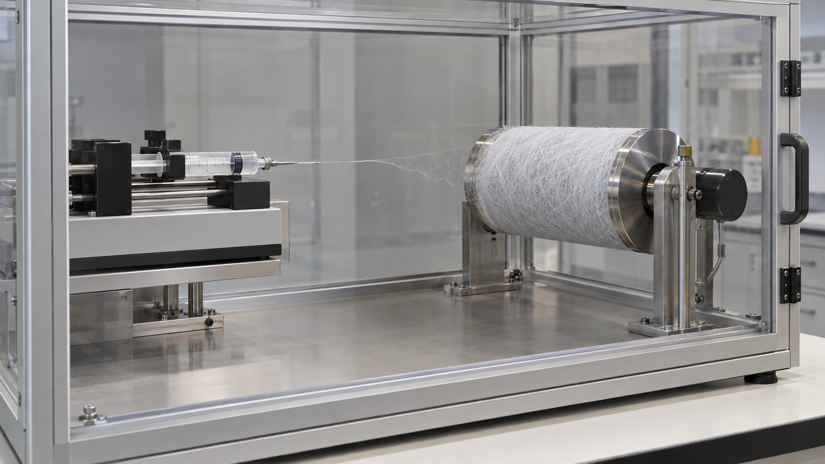
- What electrospinning and nanofibers are, in three points
- Principle: drawing a fibre with high voltage
- What sets fibre diameter: our calculation
- A materials engineer's view (1): thickness is set by entanglement, not by concentration
- Equipment: nozzle, collector and free surface
- Materials: polymers and ceramic precursors
- A materials engineer's view (2): what was “nanofiber diameter” measured with?
- Uses: filters, battery separators and medicine
- A materials engineer's view (3): each use wants a different fibre
- Volume production and its problems: uniformity and solvent
- A materials engineer's view (4): how many times the fibre's mass is the solvent?
- “Nanofiber” versus the EU's “nanomaterial”
- What this article could not confirm, and a summary
- Glossary / References / Claim-to-source audit
Sourced = stated in a published document, paper, patent or law (link given)
Our calculation = a value this article derived from assumptions it states
Not yet confirmed = a plan, outlook or matter not yet settled
Structural readings and materials-design interpretations are marked separately as Commentary.
This article explains materials, principles and processes. It does not rank any product or company, and it is not medical or safety advice.
Performance values differ in method, sample and conditions from paper to paper, so please do not set them side by side to rank them.
Whose definition of “nano” or of a regulated nanomaterial is meant matters; see our explainer on the definition and regulation of nanomaterials.
1. What electrospinning and nanofibers are, in three points
- What it does: In 1996 Reneker and Chun described electrospinning as using electrical forces to produce polymer fibres with nanometre-scale diameters. When the electrical forces at the surface of a solution or melt overcome the surface tension, an electrically charged jet is ejected, and when the jet dries or solidifies a charged fibre remains Sourced
- How fine: The review by Greiner and Wendorff describes a method that makes continuous fibres from a few micrometres down to a few nanometres in diameter and applies to virtually every soluble or fusible polymer Sourced. Note that even when called “nanofibers”, actual diameters range from a few nanometres to several micrometres (Chapter 12)
- What is hard: The small output of a single nozzle (typically around 0.01–1 g per hour, according to a review), making the diameter uniform, and the amount and toxicity of solvent Sourced (Chapters 10 and 11)
Electrospinning is a method that makes fine fibres easily but is hard to make uniform and in volume. The fineness comes from stretching the jet many thousands of times with static electricity, but the spread in thickness, bead defects, the small output per nozzle and the burden of evaporating roughly ten times the fibre's mass in solvent are the problems of industrialisation (Commentary; calculated in Chapters 10 and 11).
2. Principle: drawing a fibre with high voltage
(1) A short history
Drawing threads from a liquid with electrical force is an old idea. A 1934 US patent (A. Formhals) states that the action of an electrical field on liquids containing dissolved material, to form threads, was already known, identifies as its problem that the threads could not be removed in a technically useful form, and proposes a design in which a movable, conducting collecting device (a reel, spool or drum) also acts as the electrode that attracts the threads Sourced. The ancestor of today's drum collector is thus in a patent more than 90 years old. In 1996 Reneker and Chun reported spinning more than 20 polymers, including polyethylene oxide, nylon, polyimide, DNA, polyaramid and polyaniline, mostly from solution but also from the melt in vacuum and in air Sourced.
(2) The jet forms, bends and thins
The process can be organised in the following stages (drawing on the papers of Reneker et al. and Taylor and on the reviews).
- The Taylor cone: The drop at the nozzle tip is stretched into a cone by the electric field. In a 1964 paper Taylor showed, by theory and experiment, that a drop elongated by an electric field becomes unstable when its length is 1.9 times its equatorial diameter, and that a conical interface between two fluids can exist in equilibrium in an electric field only when the cone has a semi-vertical angle of 49.3° Sourced (Taylor's paper dealt with the disintegration of water drops in electric fields, not with spinning polymer solutions as such).
- The straight jet: The jet ejected from the tip of the cone travels in a nearly straight line for some distance. In the mathematical model of Reneker et al., the longitudinal stress caused by the external electric field acting on the charge carried by the jet stabilises the straight jet for that distance Sourced.
- The bending instability: Then a lateral perturbation grows in response to the repulsive forces between adjacent elements of charge on the jet, and an electrically driven bending instability takes over. The jet follows a complex path and is stretched and thinned by very large ratios by electrical forces. After the solvent evaporates, birefringent nanofibers remain Sourced.
- Solidification and deposition: When the solvent evaporates or the melt cools, a charged fibre remains and is directed by electrical forces onto a collector Sourced.
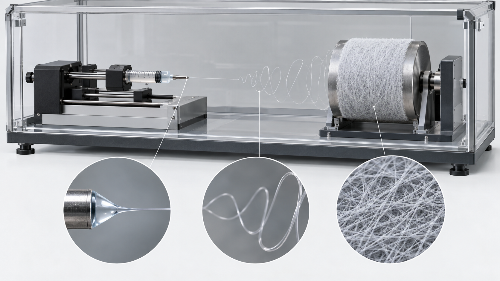
Shapes, colors and dimensions are illustrative. Consult the original schematic below for exact values and label correspondence.
View the original SVG schematic and exact annotations
Reading guide and original schematic labels: Principle of electrospinning (concept) / syringe / collector (grounded; drum or plate) / high-voltage supply (+) / Taylor cone / straight part / bending / instability / 1. Taylor cone / The field draws the drop into a cone. / Equilibrium cone: 49.3° semi-angle (Taylor) / 2. Straight jet / Leaves the tip and runs nearly straight / 3. Bending instability / Charge repulsion makes it whip sideways, / and the jet is stretched enormously / 4. Solidification / Solvent evaporates (or the melt cools) / 5. Deposition / Fibres gather on the collector as a mat / Note: conceptual; no voltages, distances or jet diameters are shown. Based on the papers of Taylor and Reneker et al. [Ref. 2, 4].
3. What sets fibre diameter: our calculation
Fibre thickness depends not only on equipment settings (voltage, flow rate, distance) but strongly on how the polymer chains in the solution are entangled. McKee et al. studied linear and branched poly(ethylene terephthalate-co-ethylene isophthalate) (PET-co-PEI) copolymers with weight-average molecular weights of 11,700 to 106,000 g/mol, relating the concentration regime of the solution (semidilute unentangled, semidilute entangled, concentrated) to the morphology of the fibres spun from it Sourced.
- For copolymers whose molecular weight is well above the entanglement molecular weight, the entanglement concentration Ce was the minimum concentration for electrospinning beaded fibres
- For uniform, bead-free fibres, 2–2.5 times Ce was the minimum concentration
- When concentration was normalised by Ce, the influence of chain length and topology disappeared, and fibre diameter scaled with the normalised concentration (C/Ce) to the power 2.6
Take the relation of McKee et al. (diameter ∝ (C/Ce)2.6) and assume it applies as it stands to this copolymer system, comparing against the lowest concentration that gives uniform fibres (C/Ce = 2) Our calculation.
- C/Ce = 2.5: (2.5 ÷ 2)2.6 ≈ 1.8 times
- C/Ce = 3: (3 ÷ 2)2.6 ≈ 2.9 times
- C/Ce = 4: (4 ÷ 2)2.6 ≈ 6.1 times
Assumptions and limits: The exponent is a relation for one copolymer, solvent and set of conditions; exponents for other polymers and solvents differ (this article has not checked them). Even so, the strong non-linearity—doubling the concentration can make the fibre six times thicker—shows the difficulty of working near the entanglement condition when aiming for finer fibres (Commentary).
4. A materials engineer's view (1): thickness is set by entanglement, not by concentration
- Do not compare conditions by concentration alone: McKee et al. showed that normalising concentration by Ce removes the influence of chain length and branching Sourced. “A 10 wt% solution” means a completely different state if the molecular weight or solvent differs. When comparing papers, check the normalised concentration (C/Ce) or the solution viscosity (Commentary).
- Beads: When the concentration is near Ce, fibres with beads like a string of pearls result Sourced (McKee et al.). In filters, beads are used to lower pressure drop, while for strength or uniformity they are defects (Chapter 8).
- Combination with the solvent: The relation of McKee et al. concerns a good solvent with no specific interaction. For systems that gel, or in which the solvent evaporates quickly, the same exponent may not hold (Commentary).
- Electrical properties: The bending instability arises from charge repulsion (Chapter 2). If the conductivity of the solution or the dielectric constant of the solvent differ, so will the degree of stretching of the jet. This article has not confirmed this point numerically in primary sources and states it only as a tendency (Commentary).
5. Equipment: nozzle, collector and free surface
The basic equipment has three parts: (1) the part that feeds the solution (syringe and pump, nozzle), (2) a high-voltage supply, and (3) the collector that receives the fibre. The review by Xue et al. organises the principle and typical apparatus of electrospinning, its methods, materials and applications, and approaches to scale-up Sourced. Here the configurations are divided into three.
(1) Needle (nozzle) type, and different collectors
The most basic arrangement ejects one jet from one nozzle and gathers it on a plate or a rotating drum. The shape of the collector sets how the fibres lie. Li, Wang and Xia reported that using as collector two conducting substrates separated by a gap makes the charged fibres stretch across the gap by electrostatic interactions and form uniaxially aligned arrays over large areas, with success for organic polymers, ceramics and composites Sourced. Theron et al. reported winding fibre onto a pointed, grounded rotating bobbin to lay polyethylene oxide fibres of 100–300 nm diameter in parallel Sourced.
(2) Coaxial nozzle (core–shell, hollow)
In 2003 Sun et al. introduced co-electrospinning: a spinnable polymer as the outer shell and a non-spinnable material as the core are extruded coaxially to form two-layer fibres. Materials that cannot be spun alone can thus be forced into one-dimensional arrangements, and nanotubes can be made in two stages instead of three, they state Sourced. In 2004 Li and Xia spun two immiscible liquids through a two-capillary spinneret and removed the core afterwards to leave hollow nanofibers (titania/polymer composites, anatase nanotubes). They state that a sol–gel precursor in the sheath liquid was necessary for stable coaxial jets and robust walls Sourced.
(3) The free-surface type, without needles
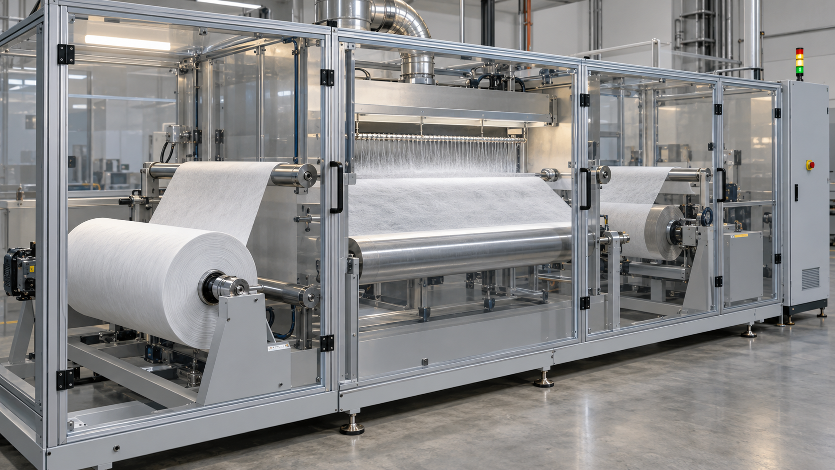
US Patent 7,585,437 B2 of Jirsak et al. (applicant: Technical University of Liberec; PCT application 8 September 2004; granted 8 September 2009) describes a method and device in which part of the circumference of a rotating charged electrode is immersed in the polymer solution, and the solution is supplied into the electric field on the surface of the electrode to attain a high spinning capacity Sourced. The review by Omer et al. describes the formation of multiple jets from the surface of a polymer solution with a charged cylindrical electrode as the first patent on this technology, followed by the world's first industrial free-surface set-up, Nanospider™ from Elmarco Sourced. We have not confirmed whether the review's first patent is the Jirsak patent above. Elmarco's own web page describes Nanospider™ as an electrospinning method using the free surface of a polymer-solution-coated electrode in a strong electrostatic field, using a thin wire electrode, with a design that allows up to four spinning units to be assembled in one industrial line (the manufacturer's description) Sourced. The chapter by Wen and Wang classifies strategies for mass production into multiple-needle, multiple-hole, free-surface, melt and multifield-assisted electrospinning Sourced.
6. Materials: polymers and ceramic precursors
(1) Polymers
The review by Greiner and Wendorff says electrospinning can be applied to virtually every soluble or fusible polymer, and that polymers can be given additives ranging from simple carbon-black particles to complex species such as enzymes, viruses and bacteria Sourced. Reneker and Chun reported spinning from solution and also from the melt in vacuum, noting that melt spinning in vacuum allows higher fields and higher temperatures than in air Sourced.
(2) Ceramics come from “precursor plus carrier polymer”
Ceramic nanofibers are made by spinning a solution that mixes a precursor with a polymer that helps spinning, and then firing to remove the polymer. In the 2003 report of Li and Xia, an ethanol solution containing PVP (poly(vinyl pyrrolidone), Mw ≈ 1,300,000) and titanium tetraisopropoxide was injected through a needle under a strong electric field and gave composite nanofibers of PVP and amorphous TiO2 (up to several centimetres long). Calcination in air at 500 °C converted them to anatase without changing their morphology, and the average diameter could be controlled from 20 to 200 nm by the PVP-to-precursor ratio, the concentrations, the field strength and the feed rate Sourced.
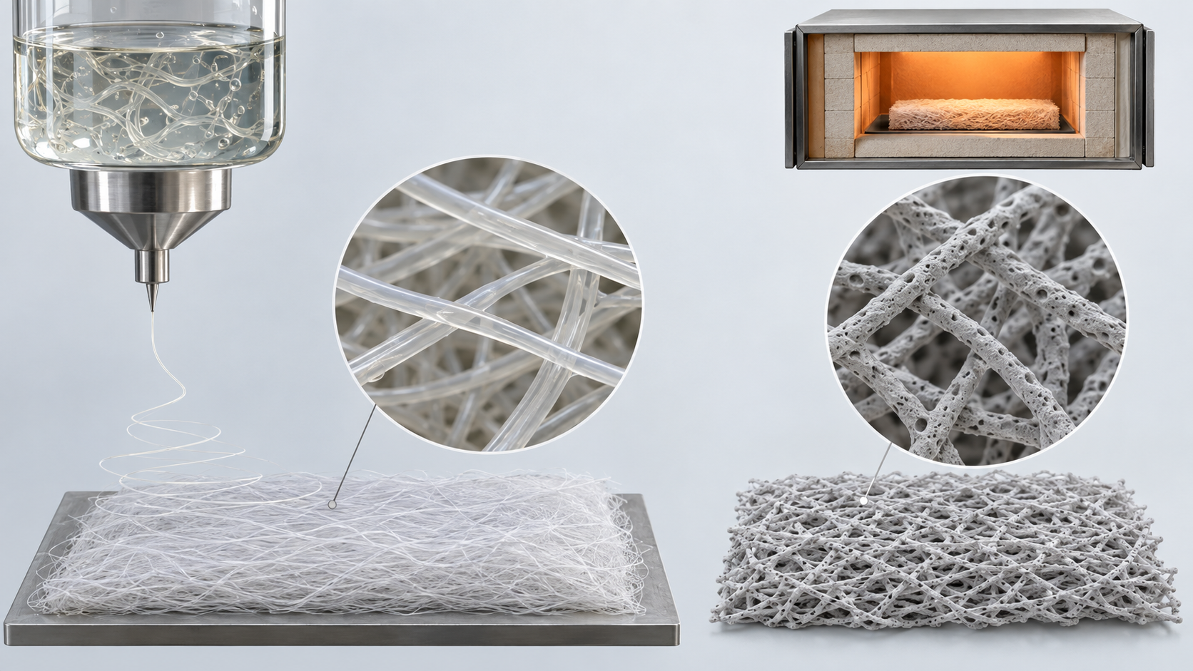
Shapes, colors and dimensions are illustrative. Consult the original schematic below for exact values and label correspondence.
View the original SVG schematic and exact annotations
Reading guide and original schematic labels: How ceramic nanofibers are made (TiO₂ example) / 1. Precursor soln. / ethanol / + PVP (carrier) / + Ti alkoxide / 2. Electrospinning / jet ejected from a / needle in a strong / electric field / 3. Composite fibre / PVP + amorphous / TiO₂ (up to / several cm long) / 4. Calcination / in air, 500 °C / removes PVP, / crystallises / 5. Product / anatase / nanofibers / 20-200 nm / For hollow fibres (coaxial spinning) / A sol-gel precursor in the sheath and an immiscible liquid in the core are extruded from a coaxial nozzle; / after spinning, the core is removed, leaving titania/polymer composite nanotubes or anatase nanotubes (Li and Xia 2004) / Commentary: the carrier polymer helps spinning and is removed during calcination (system of Li and Xia, 2003) / Note: conceptual. The numbers apply only to the system of Li and Xia 2003 [Ref. 9] / (PVP + titanium tetraisopropoxide, 500 °C calcination), not to other materials. / It does not depict the full conditions of a real instrument or process.
7. A materials engineer's view (2): what was “nanofiber diameter” measured with?
- How it is measured: Fibre diameter is generally measured from scanning electron microscope (SEM) images. Hotaling et al. made a free plug-in (DiameterJ) that automatically analyses nanofibre diameter from SEM images, state that it gave hundreds of times the sampling of manual measurement, and validated it on images of steel wires of known diameter Sourced. So how reliable an average diameter is depends on how many fibres were measured, and how (Commentary).
- Width of the distribution: As an example of Elmarco's Nanospider™ NS 8S1600U (the base unit for industrial production), the review by Omer et al. gives PA6 (nylon 6) on a cellulose substrate, 1.6 m wide, basis weight 0.03 g/m², fibre diameter 150 nm ±30%, and 20,000,000 m² per year. This is a statement quoting the manufacturer's published information, that is, a manufacturer's stated value (via a review) Sourced.
Here is what “150 nm ±30%” means, by geometry alone Our calculation.
- ±30% spans 105–195 nm. Mass per unit length is proportional to the square of the diameter, so the mass-per-length ratio of the thickest to the thinnest fibre is (195 ÷ 105)2 ≈ 3.5.
- For a cylinder, the volume-specific surface area is 4 ÷ diameter; for 150 nm, 4 ÷ (150 × 10-9 m) ≈ 2.7 × 10⁷ m²/m³ = about 27 m²/cm³. Assuming a density of 1.14 g/cm³ (an assumption), the surface area per mass is about 23 m²/g.
Assumptions and limits: We have not confirmed whether ±30% is a standard deviation or a range in the review's quotation. The volume-specific surface area is for a long cylinder and ignores voids in the mat, contacts between fibres and surface roughness. The density is assumed. Even so, it shows that even with the same average, the fraction of thin fibres and the fraction of thick fibres change the pressure drop and capture of a filter, and the pore-size distribution in a battery (Commentary).
A diameter from SEM is often a value for a dry sample coated with a thin metal layer, and may differ from the diameter in a humid environment or at high temperature. The diameter at places where fibres bundle or overlap also changes with the image-processing method. When comparing diameters, check how many fibres were measured, the image-processing method and the sample pre-treatment (Commentary; we have not confirmed concrete differences).
8. Uses: filters, battery separators and medicine
(1) Air filters
The review by Lyu et al. says that filter membranes are evaluated by a quality factor (QF), and a membrane with a high QF must have both high filtration efficiency and low pressure drop. As features of electrospun membranes it lists a low Knudsen number, slip flow that lowers pressure drop and garland-like structures that raise capture efficiency, and organises structures such as bead-on-string and multilayer designs as ways to optimise performance Sourced. The review includes example values: a PA-6 membrane (needle-free spinning with a spiral electrode) with PM filtration efficiency of 99.42% and pressure drop of 85.5 Pa; a PAN bead-on-string membrane above 99% at 27 Pa; and a GO-PAN composite membrane at 99.97% and 8 Pa Sourced. These come from different papers, and whether particle size, face velocity and test method are the same could not be confirmed, either in the review or in this article. They should not be set side by side to rank them.
(2) Battery separators
The review by Arora and Zhang says the ideal battery separator would be infinitesimally thin, offer no resistance to ionic transport in electrolytes, provide infinite resistance to electronic conductivity, be highly tortuous to prevent dendritic growth, and be inert to chemical reactions; in the real world this does not exist, and compromises are made by manipulating thickness and porosity Sourced. The review by Li et al. calls electrospun nonwovens a promising candidate for lithium-ion battery separators because of their interconnected porous structures, high porosities and large surface-to-volume ratio, and classifies them into five types: monolayer, multilayer, modified, composite and gel polymer electrolyte Sourced. What can be said here goes only as far as organising research; to what extent electrospun nonwovens are used in commercial batteries could not be confirmed in primary sources in this article.
(3) Medical uses
The review by Agarwal et al. describes electrospinning as a technique that gives nonwovens with fibres down to a few nanometres, large surface areas and ease of functionalisation, used in tissue engineering, drug release, wound dressing, enzyme immobilisation and similar Sourced. The review by Omer et al. lists as problems the toxicity of residual organic solvent and variation in properties between batches for natural polymers such as silk fibroin Sourced. The effect, safety and approval status of individual medical products must be confirmed product by product in official documents; this article does not evaluate them.
9. A materials engineer's view (3): each use wants a different fibre
- The verdict on beads reverses: In the filter review, bead-on-string structures are presented as cases where beads lower packing density and so reduce pressure drop Sourced (Lyu et al.). For uses that need uniform diameter or strength, however, beads are defects (Commentary).
- Pore size and diameter distribution: In filters the gaps between fibres govern capture; in separators the pore distribution governs prevention of internal short circuits and ease of ion passage. In both, the distribution and basis weight (mass of fibre), not the average diameter, matter in part (Commentary; see the calculation in Chapter 7).
- Combination with a substrate: The Nanospider™ example in the review of Omer et al. was a configuration in which nanofibers are laid thinly (0.03 g/m²) on a substrate such as cellulose Sourced. A nanofiber layer is thin and weak by itself, so in practice the design gives it strength by lamination to a substrate (our reading).
- Choice of material: Batteries need heat and electrolyte resistance, medicine needs biocompatibility and low residual solvent, filters need charge retention and moisture resistance; each use asks different properties of the material. That electrospinning “can do anything” also means you cannot escape designing which material meets which requirement (Commentary).
10. Volume production and its problems: uniformity and solvent
(1) Scale of output
The review by Omer et al. says typical electrospinning output is around 0.01–1 g per hour, too low for pharmaceutical requirements, and compares routes to volume production such as multiple needles, free-surface (needle-free) methods and centrifugal approaches. It says needleless and centrifugal methods have gained the most attention, with output reaching 450 g per hour in some cases Sourced. The same review cites laboratory free-surface examples of 8.6 g/h (cylinder), 6.2 g/h (disk) and 3.1 g/h (ball) for PVA fibres, 13.7 g/h for another method, about 80 g/h for a 36-orifice high-speed spinner, and for Nanospider™ 1.5 g per minute per metre of roller length with fibre diameters of 50–500 nm (each quoted from separate papers or manufacturer material) Sourced.
From the manufacturer's example quoted in Chapter 7 (PA6, cellulose substrate, 1.6 m wide, basis weight 0.03 g/m², 20,000,000 m² per year), calculate the mass of nanofiber Our calculation.
- Mass per year = 0.03 g/m² × 2.0 × 10⁷ m² = 6.0 × 10⁵ g = about 600 kg
- Averaged over 8,760 hours of continuous running (assumed): 600,000 g ÷ 8,760 h ≈ about 68 g/h
- Divided by the typical value for one needle (0.01–1 g/h), that equals about 70 to 7,000 needles
- Substrate length = 2.0 × 10⁷ m² ÷ 1.6 m = 1.25 × 10⁷ m (about 12,500 km); divided by a year's minutes, a travel speed of about 24 m per minute
- For reference, applying the review's “1.5 g per minute per metre of roller length” to a width of 1.6 m gives 1.5 × 1.6 × 60 = 144 g/h. That is the same order as the 68 g/h derived from the annual example, but the conditions differ
Assumptions and limits: We have not confirmed whether the annual example assumes continuous operation. A basis weight of 0.03 g/m² is an extremely thin layer; layers of a heavier basis weight cannot be made at the same line speed. The two values come from different conditions and machines, so this is not a like-for-like comparison (Commentary).
(2) The uniformity problem
The review by Persano et al. says that electrospinning equipment, technological solutions and materials are rapidly moving to commercialisation, and analyses the technological approaches that promise scale-up that fulfils industrial requirements for throughput, accuracy and functionality Sourced. The review by Omer et al. lists, as quality problems, variation between batches of natural polymers, toxicity from residual organic solvent, stability of active agents under heat treatment, and the fact that the process is relatively slow and time-consuming Sourced. Uniformity will be managed as the distribution of fibre diameter and basis weight across the width, the fraction of defects such as beads, and lot-to-lot reproducibility (Commentary; this article has not confirmed concrete specification or control values).
11. A materials engineer's view (4): how many times the fibre's mass is the solvent?
In solution spinning, once the polymer concentration of the solution is fixed, so is the mass of solvent per gram of fibre. Concentration differs by polymer and solvent, so here we assume a polymer concentration of 5–15 wt% Our calculation.
- Mass of solvent ÷ mass of fibre = (1 − c) ÷ c (c is the polymer mass fraction)
- c = 15%: about 5.7 times / 10%: 9 times / 5%: 19 times
- Applying a 10% assumption to the annual example of Chapter 10 (about 600 kg of fibre), the solvent evaporated is about 5.4 t per year (about 11 t at 5%)
Assumptions and limits: The concentration is assumed and differs by polymer and solvent. Not all the solution becomes fibre, and losses from unspun solution are not included (Commentary). Even so, the mass of solvent to be evaporated and handled is an order of magnitude greater than the product's mass, which shows why ventilation, recovery, exhaust treatment and control of the working environment become major items in volume production of nanofibers.
- Residual solvent: For medical use, the toxicity of residual organic solvent is cited as a problem Sourced (Omer et al.).
- Moving to milder solvents: Liverani and Boccaccini showed that poly(ε-caprolactone) fibres can be spun from less toxic and harmful (“benign”) solvents such as acetic and formic acid, while stating that such solvents usually require an accurate and longer process of optimisation Sourced. Avossa et al. describe a “building block” approach, using a variety of benign solvent compositions and additives, as a strategy that makes solvent-based electrospinning increasingly sustainable Sourced.
- Melt spinning: Reneker and Chun reported melt spinning in vacuum as a method that avoids solvent (Chapter 6). This article has not confirmed the fibre diameters or output obtainable by melt spinning.
12. “Nanofiber” versus the EU's “nanomaterial”
The name “nanofiber” and the legal term “nanomaterial” are not the same thing. Greiner and Wendorff give electrospun fibre diameters as a few micrometres down to a few nanometres, and many products called “nanofibers” exceed 100 nm (including the 150 nm of the example above) Sourced.
The Commission Recommendation of 10 June 2022 (2022/C 229/01) defines a nanomaterial as a material consisting of solid particles, where 50% or more of the particles in the number-based size distribution fulfil at least one of the following conditions: (a) one or more external dimensions of the particle are in the range 1 nm to 100 nm; (b) the particle has an elongated shape, such as a rod, fibre or tube, where two external dimensions are smaller than 1 nm and the other is larger than 100 nm; (c) the particle has a plate-like shape, where one external dimension is smaller than 1 nm and the other dimensions are larger than 100 nm. It further provides that a material with a specific surface area by volume of less than 6 m²/cm³ shall not be considered a nanomaterial Sourced.
- A fibre of 100 nm diameter or less can meet condition (a), but a fibre of 150 nm falls outside the 1–100 nm range in diameter. What counts is whether particles of 100 nm or less make up 50% or more of the number-based distribution (our reading).
- The volume-specific surface area of a cylinder is 4 ÷ diameter, which reaches 6 m²/cm³ at a diameter of 667 nm (Fig. 2) Our calculation. This is a reference value converting the recommendation's exclusion threshold by cylinder geometry alone, and does not indicate how a nonwoven product is treated under regulation.
- This recommendation is a recommended definition for EU policy and legislative use; its treatment under individual laws (REACH, cosmetics, food and so on) has to be checked law by law. How a formed article such as a nonwoven fits the recommendation's “material” and “particle” could not be confirmed in this article Not yet confirmed
13. What this article could not confirm, and a summary
- Manufacturer's production specifications: The Nanospider™ figures of Elmarco (PA6, 1.6 m wide, basis weight 0.03 g/m², fibre diameter 150 nm ±30%, 20,000,000 m² per year, 1.5 g/min per m) are quotations in the review by Omer et al. and could not be confirmed on the manufacturer's own web page. Whether “±30%” is a standard deviation or a range is also unconfirmed.
- Use of battery separators in the market: To what extent electrospun nonwovens are used in commercial batteries could not be confirmed in primary sources.
- Test conditions for filters: The test conditions (particle size, face velocity) behind the capture efficiencies and pressure drops collected in the review were not checked.
- Regulation of solvents: The treatment under the EU REACH Regulation of solvents often used in spinning, such as DMF, has not been looked into.
- Change in diameter on calcination of ceramics: How much the diameter shrinks on calcination could not be confirmed from the abstracts of the papers cited here.
- Standards and evaluation: The numbers and titles of ISO standards on nanofibre terminology and evaluation are not given because the standards body's website could not be opened to confirm them.
- Approval status of medical products: We do not evaluate individual products; approval must be confirmed product by product in official documents.
- High voltage stretches a liquid jet. The fibre thins through the Taylor cone, the straight jet, the bending instability and solidification Sourced
- Thickness is set by entanglement, not by concentration. In one copolymer system, uniform fibres appear from about C/Ce = 2 and the diameter is proportional to (C/Ce)2.6 Sourced. A doubling of concentration can make the diameter about six times larger Our calculation
- Ceramics are made by spinning precursor plus carrier polymer and firing. In the TiO2 example, anatase of 20–200 nm Sourced
- Each use wants a different fibre. Filters, efficiency and pressure drop; separators, porosity and ion conduction; medicine, residual solvent and compatibility Sourced
- The walls to volume production are output, uniformity and solvent. One needle gives roughly 0.01–1 g per hour; free-surface and similar methods raise it by orders of magnitude; and several to ten or more times the fibre's mass in solvent must be handled Sourced Our calculation
- “Nanofiber” and the EU's “nanomaterial” are different. Many fibres exceed 100 nm. The treatment of formed articles is Not yet confirmed
14. Glossary
- Electrospinning
- Making fine fibres by drawing a solution or melt into a jet with high voltage.
- Taylor cone
- The cone shape into which a drop is drawn by an electric field; the jet leaves its tip.
- Bending instability
- The sideways whipping of the jet from charge repulsion, which stretches it into a widening spiral.
- Collector
- The electrode that receives the fibre: a plate, drum, or the gap between two substrates.
- Free-surface type
- A needle-free method in which many jets leave the free surface of solution on an electrode.
- Coaxial spinning
- Feeding inner and outer liquids together through a double nozzle to make core–shell or hollow fibres.
- Entanglement concentration (Ce)
- The concentration at which polymer chains in solution begin to entangle; uniform fibres were reported to need 2–2.5 Ce or more.
- Bead
- A small spherical swelling along a fibre; it can be a defect or a feature.
- Nonwoven
- A sheet made by entangling or stacking fibres without weaving.
- Quality factor (QF)
- An index for filters that judges capture efficiency and pressure drop together.
- Basis weight
- Mass per unit area (g/m²).
- VSSA
- Volume-specific surface area, the surface area per unit volume. Under the EU recommendation a material below 6 m²/cm³ is not a nanomaterial.
- Building-block approach
- Combining benign solvent compositions and additives to make solvent-based spinning more sustainable.
15. References (primary sources)
- Formhals A US Patent 1,975,504, Process and apparatus for preparing artificial threads (2 October 1934) — patents.google.com
- Taylor G Disintegration of water drops in an electric field. Proc R Soc Lond A 1964;280:383–397 — doi.org/10.1098/rspa.1964.0151
- Reneker DH, Chun I Nanometre diameter fibres of polymer, produced by electrospinning. Nanotechnology 1996;7:216–223 — doi.org/10.1088/0957-4484/7/3/009
- Reneker DH et al. Bending instability of electrically charged liquid jets of polymer solutions in electrospinning. J Appl Phys 2000;87:4531–4547 — doi.org/10.1063/1.373532
- Greiner A, Wendorff JH Electrospinning: A Fascinating Method for the Preparation of Ultrathin Fibers. Angew Chem Int Ed 2007;46:5670–5703 — doi.org/10.1002/anie.200604646
- Li D, Xia Y Electrospinning of Nanofibers: Reinventing the Wheel? Adv Mater 2004;16:1151–1170 — doi.org/10.1002/adma.200400719
- Xue J et al. Electrospinning and Electrospun Nanofibers: Methods, Materials, and Applications. Chem Rev 2019;119:5298–5415 — doi.org/10.1021/acs.chemrev.8b00593
- McKee MG et al. Correlations of Solution Rheology with Electrospun Fiber Formation of Linear and Branched Polyesters. Macromolecules 2004;37:1760–1767 — doi.org/10.1021/ma035689h
- Li D, Xia Y Fabrication of Titania Nanofibers by Electrospinning. Nano Lett 2003;3:555–560 — doi.org/10.1021/nl034039o
- Li D, Xia Y Direct Fabrication of Composite and Ceramic Hollow Nanofibers by Electrospinning. Nano Lett 2004;4:933–938 — doi.org/10.1021/nl049590f
- Sun Z et al. Compound Core–Shell Polymer Nanofibers by Co-Electrospinning. Adv Mater 2003;15:1929–1932 — doi.org/10.1002/adma.200305136
- Li D, Wang Y, Xia Y Electrospinning of Polymeric and Ceramic Nanofibers as Uniaxially Aligned Arrays. Nano Lett 2003;3:1167–1171 — doi.org/10.1021/nl0344256
- Jirsak O et al. (Technicka Univerzita v Liberci) US Patent 7,585,437 B2, Method of nanofibres production from a polymer solution using electrostatic spinning and a device for carrying out the method (filed 8 September 2004; granted 8 September 2009) — patents.google.com
- Elmarco Nanospider technology (the manufacturer's web page) — elmarco.com
- Persano L et al. Industrial Upscaling of Electrospinning and Applications of Polymer Nanofibers: A Review. Macromol Mater Eng 2013;298:504–520 — doi.org/10.1002/mame.201200290
- Omer S et al. Scale-up of Electrospinning: Market Overview of Products and Devices for Pharmaceutical and Biomedical Purposes. Pharmaceutics 2021;13:286 — doi.org/10.3390/pharmaceutics13020286
- Wen X, Wang L Mass Production of Electrospun Nanofibers. In: Electrospinning, Wiley 2024, pp. 29–43 — doi.org/10.1002/9783527841479.ch3
- Lyu C et al. Electrospinning of Nanofibrous Membrane and Its Applications in Air Filtration: A Review. Nanomaterials 2021;11:1501 — doi.org/10.3390/nano11061501
- Li Y, Li Q, Tan Z A review of electrospun nanofiber-based separators for rechargeable lithium-ion batteries. J Power Sources 2019;443:227262 — doi.org/10.1016/j.jpowsour.2019.227262
- Arora P, Zhang Z Battery Separators. Chem Rev 2004;104:4419–4462 — doi.org/10.1021/cr020738u
- Agarwal S, Wendorff JH, Greiner A Use of electrospinning technique for biomedical applications. Polymer 2008;49:5603–5621 — doi.org/10.1016/j.polymer.2008.09.014
- Liverani L, Boccaccini AR Versatile Production of Poly(Epsilon-Caprolactone) Fibers by Electrospinning Using Benign Solvents. Nanomaterials 2016;6:75 — doi.org/10.3390/nano6040075
- Avossa J et al. Electrospinning based on benign solvents: current definitions, implications and strategies. Green Chem 2022;24:2347–2375 — doi.org/10.1039/d1gc04252a
- Hotaling NA et al. DiameterJ: A validated open source nanofiber diameter measurement tool. Biomaterials 2015;61:327–338 — doi.org/10.1016/j.biomaterials.2015.05.015
- European Commission Commission Recommendation of 10 June 2022 on the definition of nanomaterial (2022/C 229/01; Official Journal C 229/1, 14 June 2022) — eur-lex.europa.eu
- Theron A, Zussman E, Yarin AL Electrostatic field-assisted alignment of electrospun nanofibres. Nanotechnology 2001;12:384–390 — doi.org/10.1088/0957-4484/12/3/329
16. Claim-to-source audit
| Claim in the text | Basis | Label |
|---|---|---|
| The 1934 US patent (Formhals): that forming threads in an electric field was already known, that threads could not be removed in a useful form before, and the proposal of a conducting movable collecting device (reel, spool, drum) that doubles as the attracting electrode | Reference 1 https://patents.google.com/patent/US1975504A/en | Sourced |
| That a drop elongated by an electric field becomes unstable at a length 1.9 times its equatorial diameter, and that a conical interface between two fluids can be in equilibrium in an electric field only at a semi-vertical angle of 49.3° (a paper on the disintegration of water drops) | Reference 2 https://doi.org/10.1098/rspa.1964.0151 | Sourced |
| That electrospinning produces polymer fibres of nanometre-scale diameter by electrical forces, that a charged jet is ejected when the forces overcome surface tension, that more than 20 polymers were spun (mostly from solution, some from the melt), and that melt spinning in vacuum allows higher fields and temperatures | Reference 3 https://doi.org/10.1088/0957-4484/7/3/009 | Sourced |
| That the jet runs straight, then bends through an electrically driven instability from charge repulsion, is stretched and thinned by very large ratios, and leaves birefringent nanofibers once the solvent evaporates; that the straight part is stabilised by the longitudinal stress from the external field | Reference 4 https://doi.org/10.1063/1.373532 | Sourced |
| That fibre diameters range from a few micrometres to a few nanometres, and that the method applies to virtually every soluble or fusible polymer with additives from carbon black to enzymes, viruses and bacteria | Reference 5 https://doi.org/10.1002/anie.200604646 | Sourced |
| That the review covers electrospinning of polymers, composites and ceramics, with set-ups, mechanisms and theoretical models, control (diameter, morphology, composition, alignment) and applications | Reference 6 https://doi.org/10.1002/adma.200400719 | Sourced |
| That the review covers the principle and typical apparatus of electrospinning, methods, materials, applications, scale-up approaches and commercial products | Reference 7 https://doi.org/10.1021/acs.chemrev.8b00593 | Sourced |
| For PET-co-PEI copolymers (Mw 11,700–106,000 g/mol): Ce as the minimum concentration for beaded fibres, 2–2.5 Ce for uniform bead-free fibres, and fibre diameter scaling with the normalised concentration C/Ce to the power 2.6 | Reference 8 https://doi.org/10.1021/ma035689h | Sourced |
| That an ethanol solution of PVP (Mw about 1,300,000) and titanium tetraisopropoxide gives PVP/amorphous TiO₂ composite nanofibers (up to several cm), that calcination in air at 500 °C converts them to anatase, and that the average diameter is controllable over 20–200 nm | Reference 9 https://doi.org/10.1021/nl034039o | Sourced |
| That two immiscible liquids spun from a coaxial two-capillary spinneret, with the core removed afterwards, give hollow nanofibers (titania/polymer composites, anatase nanotubes), and that a sol–gel precursor in the sheath liquid was necessary | Reference 10 https://doi.org/10.1021/nl049590f | Sourced |
| That co-electrospinning with a spinnable shell polymer and a non-spinnable core makes two-layer fibres, and that nanotubes can be made in two stages instead of three | Reference 11 https://doi.org/10.1002/adma.200305136 | Sourced |
| That a collector of two conducting substrates separated by a gap gives uniaxially aligned fibre arrays over large areas | Reference 12 https://doi.org/10.1021/nl0344256 | Sourced |
| That Theron et al. wound fibre onto a pointed, grounded rotating bobbin and laid 100–300 nm PEO fibres in parallel | Reference 26 https://doi.org/10.1088/0957-4484/12/3/329 | Sourced |
| The patent of Jirsak et al. (Technical University of Liberec; PCT filing 8 September 2004; granted 8 September 2009): a method and device in which part of the circumference of a rotating charged electrode is immersed in solution for spinning | Reference 13 https://patents.google.com/patent/US7585437B2/en | Sourced |
| That Nanospider is a needle-free method that uses the free surface of a solution-coated electrode in a strong electrostatic field, that it uses a thin wire electrode, and that up to four spinning units can be assembled in an industrial line (the manufacturer's description) | Reference 14 https://www.elmarco.com/nanospider | Sourced |
| That equipment, technological solutions and materials are moving towards commercialisation, and the analysis of approaches that promise scale-up in throughput, accuracy and functionality | Reference 15 https://doi.org/10.1002/mame.201200290 | Sourced |
| That typical output is 0.01–1 g/h; that needleless and centrifugal methods have gained the most attention with output up to 450 g/h in some cases; 8.6 (cylinder), 6.2 (disk) and 3.1 g/h (ball) for PVA; 13.7 g/h; about 80 g/h; Nanospider at 1.5 g/min per metre and 50–500 nm; NS 8S1600U (PA6, cellulose substrate, 1.6 m, 0.03 g/m², 150 nm ±30%, 20,000,000 m² per year); residual solvent toxicity, batch variation and slow process | Reference 16 https://doi.org/10.3390/pharmaceutics13020286 | Sourced |
| That strategies for mass production are classified into multiple-needle, multiple-hole, free-surface, melt and multifield-assisted electrospinning | Reference 17 https://doi.org/10.1002/9783527841479.ch3 | Sourced |
| That the quality factor QF combines high efficiency and low pressure drop; slip flow and garland structures; bead-on-string and multilayer structures; the example values (PA-6 99.42% and 85.5 Pa; PAN above 99% and 27 Pa; GO-PAN 99.97% and 8 Pa) | Reference 18 https://doi.org/10.3390/nano11061501 | Sourced |
| That electrospun nonwovens have interconnected pores, high porosity and a large surface area, are a promising separator candidate for lithium-ion batteries, and fall into five types (monolayer, multilayer, modified, composite, gel polymer electrolyte) | Reference 19 https://doi.org/10.1016/j.jpowsour.2019.227262 | Sourced |
| The conditions of an ideal separator (infinitesimally thin, no ionic resistance, infinite electronic resistance, tortuous enough to block dendrites, chemically inert) and that real separators compromise through thickness and porosity | Reference 20 https://doi.org/10.1021/cr020738u | Sourced |
| That electrospinning is used in tissue engineering, drug release, wound dressing and enzyme immobilisation | Reference 21 https://doi.org/10.1016/j.polymer.2008.09.014 | Sourced |
| That PCL fibres can be spun from benign solvents such as acetic and formic acid, and that such solvents usually need more accurate and longer optimisation | Reference 22 https://doi.org/10.3390/nano6040075 | Sourced |
| That a building-block approach with benign solvent compositions and additives is a strategy for more sustainable solvent-based electrospinning | Reference 23 https://doi.org/10.1039/d1gc04252a | Sourced |
| That DiameterJ analyses nanofibre diameter from SEM images, gave hundreds of times the sampling of manual measurement, and was validated on steel wires of known diameter | Reference 24 https://doi.org/10.1016/j.biomaterials.2015.05.015 | Sourced |
| The nanomaterial definition in Commission Recommendation 2022/C 229/01 (10 June 2022): 50% or more of particles in the number-based distribution meeting (a) an external dimension of 1–100 nm, (b) an elongated shape with two dimensions below 1 nm and one above 100 nm, or (c) a plate shape; and exclusion of materials below 6 m²/cm³ | Reference 25 https://eur-lex.europa.eu/legal-content/EN/TXT/?uri=CELEX:32022H0614(01) | Sourced |
| Diameters of about 1.8, 2.9 and 6.1 times at C/Ce = 2.5, 3 and 4 relative to C/Ce = 2 (the relation diameter ∝ (C/Ce)^2.6 applied to the copolymer system) | our own calculation | Our calculation |
| A mass-per-length ratio of about 3.5 for the ±30% diameter spread (105–195 nm); VSSA of 4 ÷ diameter: 40 at 100 nm, 27 at 150 nm, 8 at 500 nm and 6 m²/cm³ at 667 nm; about 23 m²/g at an assumed density of 1.14 g/cm³ | our own calculation | Our calculation |
| About 600 kg from 0.03 g/m² × 20,000,000 m²; an average of about 68 g/h; about 70–7,000 needles; about 12,500 km of substrate and about 24 m per minute; about 144 g/h from 1.5 g/min per m at 1.6 m | our own calculation | Our calculation |
| Solvent mass ÷ fibre mass = (1 − c) ÷ c: about 5.7, 9 and 19 times at c = 15%, 10% and 5%; about 5.4 t per year of solvent (about 11 t at 5%) for the annual example at a 10% assumption | our own calculation | Our calculation |
| The organisation of principle, equipment, materials and uses; how to read comparisons of entanglement, concentration and normalised concentration; the differing design of filters, separators and medical uses; the reversal of the verdict on beads; design with a substrate; the reading of the scale of solvent mass; and the point that “nanofiber” and the legal “nanomaterial” are different | this article (commentary) | Commentary |
| How a formed article (a nonwoven) is treated under the EU recommendation and individual laws; REACH treatment of solvents such as DMF; the numbers and titles of ISO standards on nanofibers; the meaning of the manufacturer's ±30%; the use of electrospun separators in commercial batteries | could not be confirmed within the scope of this article (our own note) | Not yet confirmed |
Last updated October 2026. Sources are limited to primary material (peer-reviewed papers, patent specifications, a manufacturer's own web page and a European Commission recommendation). The Nanospider™ figures (basis weight, fibre diameter, annual output and so on) are quoted by the review of Omer et al. from manufacturer material and could not be confirmed on the manufacturer's own web page. The output figures come from reports under differing conditions and do not rank methods. Because the article includes structural readings and materials-design interpretations, those are marked as Commentary and kept separate from sourced fact. The details of the manufacturer's figures (the meaning of ±30%), the treatment of solvents such as DMF under REACH, the numbers of ISO standards on nanofibers, the treatment of formed articles under the EU recommendation, and the use of electrospun separators in commercial batteries are not covered, because they could not be confirmed in primary sources. This article explains materials, principles and processes. It does not rank any product or company, and it is not medical or safety advice. The hero image and Fig. 7 are AI-generated images and the other figures are vector drawings; none of them shows a real instrument, product or measurement result.