TECHNOLOGY EXPLAINER
Silicon Anodes and Nanostructured Electrodes
— how do you hold a material that swells to 3–4 times its volume inside a battery?
Silicon can store roughly ten times as much lithium as graphite in theory, but when it takes up lithium its volume changes by about 300% (400% in some reports). The particles crack, the protective film on their surface (the SEI) breaks, and lithium and electrolyte keep being consumed to rebuild it. This article covers nanostructuring (particles, wires, porous structures, and carbon shells with void space), how to read the “%” in silicon-content claims, prelithiation, and what is publicly documented about commercialization, drawing on peer-reviewed papers and official company and public-agency documents, from a materials engineer's point of view. It is not investment, procurement or design advice.
- What a silicon anode is, in three points
- Why it cracks: how to read “about 300%”, and the ~150 nm boundary
- Our calculation: how much lighter does the anode get when silicon is blended in?
- A materials engineer's view (1): the “%” in silicon content is a percentage of what?
- Four nanostructure designs: reported values and conditions
- SEI instability: every crack costs electrolyte and lithium
- A materials engineer's view (2): nanostructuring cuts cracking but adds surface area
- Prelithiation: paying the first-cycle loss in advance
- Commercialization: what official documents can confirm
- Strengths, weaknesses and open issues
- Glossary / References / Claim-to-source audit
Sourced = stated in published material (link given)
Our calculation = a value this article derived from assumptions it states
Not yet confirmed = a plan or target with no confirmed track record
Structural readings and materials-design interpretations are marked separately as Commentary. An Inference is shown in bold.
Manufacturers' figures are manufacturer's stated values; where the test conditions could not be confirmed in public documents, the text says so.
1. What a silicon anode is, in three points
Graphite is still the main anode material in lithium-ion batteries. A silicon anode replaces part, or all, of that graphite with silicon (Si) or a silicon-containing composite.
- Why it is attractive: Panasonic Energy's own releases state that silicon's theoretical capacity is about ten times that of graphite Sourced [Reference 14, 15]. A 2008 paper gives silicon's theoretical charge capacity as 4,200 mAh/g Sourced [Reference 1].
- What the problem is: taking up lithium changes the volume enormously. A review says about 300% [Reference 2]; the 2008 paper says 400% [Reference 1] Sourced. Section 2 sorts out the difference.
- How it is tackled: make the silicon nanostructured so it cracks less, combine it with carbon to build in void space, and compensate the first-cycle loss by prelithiation. In actual products, blending into graphite appears to have come first (Commentary; Section 9 checks what official documents say).
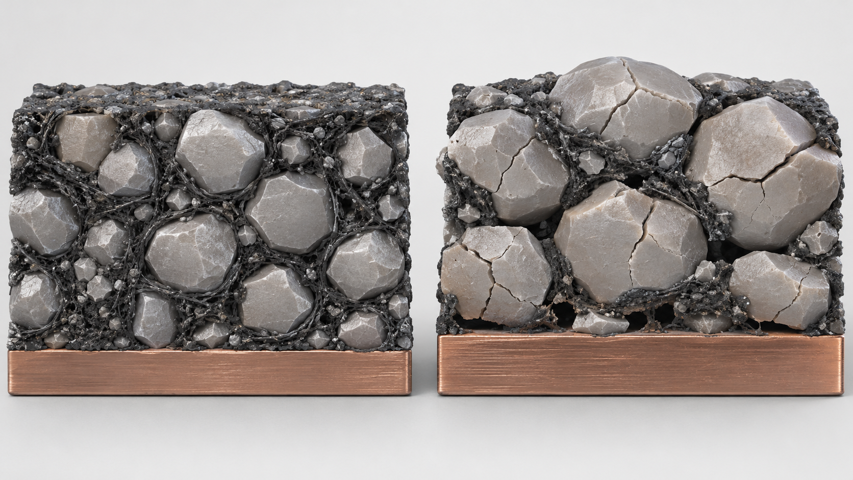
Nanostructuring reduces cracking, but it increases surface area. Particle size and shape can reduce cracking, yet more surface means more area for the electrolyte to react on. Designing a silicon anode is a matter of solving both problems at once.
2. Why it cracks: how to read “about 300%”, and the ~150 nm boundary
(1) Do “about 300%” and “400%” contradict each other?
Sources give silicon's volume change as about 300% (a 2016 review [Reference 2] and a 2014 paper [Reference 10]) or 400% (a 2008 paper [Reference 1]) Sourced. The abstracts do not explain how each figure is defined or under what conditions. When you read such a number, check at least three things.
- What the percentage is relative to: is it the increase over the original volume, or the expanded volume as a percentage of the original? If the volume becomes four times larger, the increase is 300%, and one could also write “swells to 400%” Our calculation.
- How far lithiation went: the volume depends on how much lithium has been inserted (which Li–Si phase).
- Particle, electrode or cell: the volume change of one particle is not the same as the thickness change of a whole electrode.
We could not confirm from the abstracts we consulted which definition was used. We suggest using the figure only to get a sense of scale (“close to 3–4 times”), not as a design value (Commentary).
Shapes, colors and dimensions are illustrative. Consult the original schematic below for exact values and label correspondence.
View the original SVG schematic and exact annotations
Reading guide and original schematic labels: Volume change when a silicon particle takes up lithium (concept) / Note: assumes a 150 nm sphere swelling isotropically to 4x its volume (panels 1 and 2 share a scale; panel 3 does not). / 1. Before lithiation / 2. After uptake / 3. A larger particle / Diameter 150 nm / Crystalline silicon / Diameter ~238 nm (our calculation) / Dotted line: original size / Above ~150 nm, surface cracks / were reported on first uptake [3] / Note: ~238 nm = 150 nm x cube root of 4 (about 1.59). The 4x volume is our assumption, not a measured value. / Note: the ~150 nm boundary comes from observing single particles on first lithiation; it does not guarantee electrode lifetime.
(2) About 150 nm: cracking starts at the surface, not the centre
Liu et al. watched silicon nanoparticles inside a transmission electron microscope (in situ TEM) during their first lithiation. Particles with a diameter below about 150 nm did not crack; larger particles first developed surface cracks and then fractured Sourced [Reference 3].
The paper attributes this to the way crystalline silicon is lithiated: a boundary between an inner core of pristine silicon and an outer shell of amorphous Li–Si alloy moves inward. This puts the surface layer under circumferential tension, which starts surface cracks, the authors explain Sourced [Reference 3]. In small particles the stored strain energy is too low for the cracks to propagate, so they do not fracture.
This result shows why nanostructuring works mechanically: make the particles small and you avoid the conditions in which cracks propagate.
The conditions matter, however. According to the abstract, the observation is of a single particle on its first lithiation. In a real electrode the particles are surrounded by binder and conductive additive, wetted by electrolyte, and cycled hundreds of times. Resisting cracks and having a long cycle life are different things; the latter is governed by the surface and SEI issues discussed in the following sections (Commentary).
(3) Another lever: limiting voltage or capacity
Some reports reduce expansion through operating conditions rather than nanostructure. In 2004, Obrovac and Christensen showed that at room temperature highly lithiated amorphous silicon crystallizes abruptly near 50 mV into a new Li–Si phase, and that stopping charge/discharge above 50 mV avoids crystalline phases and improves cycling Sourced [Reference 5]. A 2007 report showed that constant-current/constant-voltage (CCCV) charging can limit the capacity of crystalline silicon so that it cycles reversibly Sourced [Reference 6].
In other words, not using all of the capacity is itself a design variable for limiting expansion (Commentary). As shown later, practical cell datasheets likewise list different capacity and cycle-life conditions for each product.
3. Our calculation: how much lighter does the anode get when silicon is blended in?
We compute, with a simple weighted average, how many grams of anode active material are needed per ampere-hour when a silicon-based material is blended into graphite by mass Our calculation.
- Assumptions: graphite effective capacity 350 mAh/g; silicon-based material effective capacity 1,500 mAh/g (both are illustrative values we assumed). The blend's capacity is the mass-weighted average.
- Formula: active material per Ah = 1,000 ÷ blend capacity (mAh/g)
- Results: 5 mass% silicon-based material gives 407.5 mAh/g, or 2.45 g/Ah (−14% versus graphite alone). 10% gives 465 mAh/g, 2.15 g/Ah (−25%). 20% gives 580 mAh/g, 1.72 g/Ah (−40%). 100% gives 1,500 mAh/g, 0.67 g/Ah (−77%).
- Another view: at 10 mass%, the silicon-based material supplies 150 ÷ 465 = about 32% of the capacity. One tenth of the mass supplies nearly a third of the capacity.
Assumptions and limits: this is a calculation of anode active-material mass only. Cell energy density does not rise by the same proportion: the cathode, current collectors, separator, electrolyte and packaging are unchanged, and volumetric capacity, first-cycle efficiency and the design needed to absorb swelling also matter. 350 and 1,500 mAh/g are illustrative assumptions, not values for any real material.
4. A materials engineer's view (1): the “%” in silicon content is a percentage of what?
Documents on silicon anodes contain several kinds of “%”. The same symbol often means different things, and putting them side by side invites misreading.
- Blend ratio: what mass percentage of a blend with graphite is silicon-based material? Panasonic Energy says it will increase the share of silicon but gives no figure for the current share [Reference 14, 15].
- Silicon inside a composite particle: in a particle that combines carbon and silicon, how many mass percent is silicon? Do not read a number in a product name as a content. For example, Group14 explains that the “55” in SCC55 is the number of the 55th formulation iteration Sourced [Reference 18].
- “Silicon” in SiOx systems: silicon oxide contains oxygen, so one must check whether the mass percentage is expressed as silicon atoms or as the whole oxide (the official documents we checked did not define this).
- Share of capacity: as the calculation above shows, a silicon-based material at 10 mass% can supply nearly a third of the capacity Our calculation.
- “+x%” in energy density: compared with what (the same cell with a graphite anode, or the best competing cell), and is it a material value or a cell value? Sila states “20% over the industry's best-performing cells” [Reference 16] and Group14 states “up to 50% over conventional lithium-ion batteries” [Reference 18, 19], but neither page gives test conditions. Nexeon says in its own release that its material for Panasonic has the potential to raise cell energy density by “up to 50%” [Reference 22], while Panasonic's release says only that it could “significantly” raise it [Reference 14].
Four questions to ask: (1) What is the denominator? (2) What is it compared with? (3) Is it a material value or a cell value? (4) What are the test conditions (current, temperature, voltage range, cycle count)? A “%” that answers none of these can indicate a trend but should not be used as a basis for comparison (Commentary).
5. Four nanostructure designs: reported values and conditions
The basic research on silicon's volume change, stress and fracture is collected in a 2013 review Sourced [Reference 4]. Building on that knowledge, nanostructures can be sorted roughly as follows (a simplification by this article of the classification in a review [Reference 2]).
| Design | Representative report | Reported values (as far as the abstract states) | This article's reading |
|---|---|---|---|
| Nanoparticles | Liu et al. 2012, ACS Nano [3] | Particles smaller than ~150 nm did not crack on first lithiation; larger ones developed surface cracks and fractured (in situ TEM, single particles) | Gives a mechanical explanation of cracking; separate from electrode lifetime |
| Nanowires | Chan et al. 2008, Nature Nanotechnology [1] | Reached the theoretical charge capacity (4,200 mAh/g) and kept a discharge capacity close to 75% of that maximum with little fading. The authors say the wires accommodate strain without pulverization and give good electronic contact and short lithium-insertion distances | Cycle count, current and cell configuration could not be confirmed from the abstract |
| Porous / hierarchical | Magasinski et al. 2010, Nature Materials [7] | Rigid spherical particles containing nanoscale silicon with irregular channels; internal porosity accommodates the volume change. Reversible capacity 1,950 mAh/g (described as more than five times that of state-of-the-art anodes) and stable | The abstract says the aim was safe, easy-to-handle particles |
| Shell with void space (yolk-shell) | Liu et al. 2012, Nano Letters [9] | Commercial silicon nanoparticles sealed in thin carbon shells with designed void space. About 2,800 mAh/g (C/10), 74% capacity retention after 1,000 cycles, Coulombic efficiency 99.84% | Fabrication needs no special equipment and is mostly at room temperature, the abstract says. The explanation is that the SEI on the shell surface stays stable |
| Shell with void space (pomegranate) | Liu et al. 2014, Nature Nanotechnology [10] | Carbon-coated silicon nanoparticles gathered into micrometre-size pouches with a thicker carbon layer. 97% retention after 1,000 cycles, Coulombic efficiency 99.87%, volumetric capacity 1,270 mAh/cm³. Stable even at an areal capacity of 3.7 mAh/cm² (stated to be at the level of commercial lithium-ion batteries) | Whether the areal capacity is at a practical level is a key check when reading laboratory results |
| Double-walled nanotubes | Wu et al. 2012, Nature Nanotechnology [8] | An active silicon nanotube surrounded by an ion-permeable silicon oxide shell. In half cells, over 6,000 cycles with more than 85% of initial capacity retained. Charge capacity about eight times that of carbon anodes; charging rates up to 20C | The expanding inner surface never meets the electrolyte. Note that this is a half-cell result |
| Composites with graphite | Li et al. 2021, Energy Storage Materials (review) [13] | Electrodes that combine a tough graphite framework with silicon's high capacity are described as promising | The form most likely to be used first in practice (Section 9) |
All Sourced (paper abstracts and bibliographic data; References 1, 3, 4, 7, 8, 9, 10, 13). Conditions differ from paper to paper, so the values cannot be ranked against each other.
The pomegranate paper states that its design remained stable even when areal capacity was raised to 3.7 mAh/cm², described as the level of commercial lithium-ion batteries Sourced [Reference 10]. That this is spelled out suggests that a number obtained with a thin electrode may not carry over to a thick practical electrode (Commentary). The thicker the electrode, the more the swelling-induced thickness change, ion diffusion distance and potential distribution inside the electrode matter.
When reading a new paper, before the capacity and cycle numbers, look for (1) areal capacity (mAh/cm²), (2) electrolyte type and additives, (3) the counter electrode (half cell or full cell), and (4) the voltage window. They show how far the result is from practice.
6. SEI instability: every crack costs electrolyte and lithium
The SEI (solid electrolyte interphase) is a thin film that forms on the anode surface; in liquid-electrolyte batteries it stops the electrode from reacting further with the electrolyte. On silicon, the film is stretched and broken every time the volume changes, and a new film forms on the freshly exposed surface. A review lists the challenges of silicon anodes as large volume change, low electrical conductivity, and SEI instability caused by repeated volume change Sourced [Reference 2]. The pomegranate paper likewise names structural degradation and SEI instability caused by the volume change, along with side reactions with the electrolyte [Reference 10].
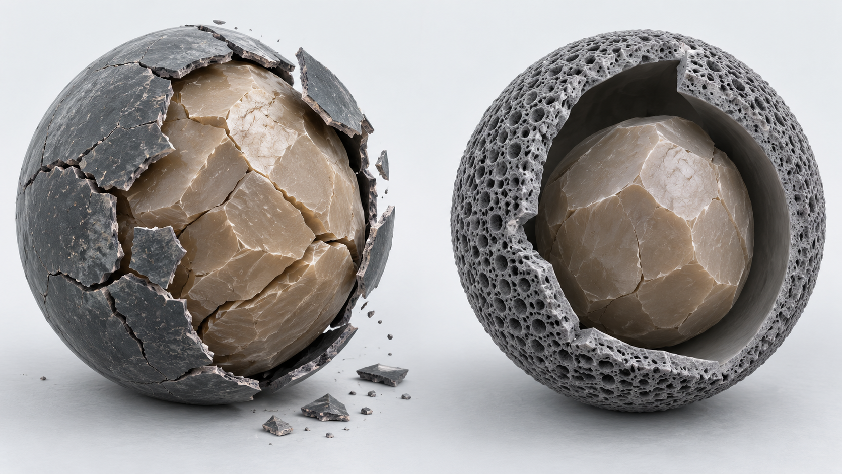
Shapes, colors and dimensions are illustrative. Consult the original schematic below for exact values and label correspondence.
View the original SVG schematic and exact annotations
Reading guide and original schematic labels: SEI instability and the shell-with-void countermeasure (concept) / No void: the film breaks and re-forms / Shell with void: SEI stays outside / 1. Forms first / 2. Swells, cracks / 3. Re-forms / Thin film / Fresh surface exposed / Film gets thicker / Each cycle uses up lithium and electrolyte / Before charge / After lithiation / Void inside the shell / Shell designed not to swell / Swelling is absorbed inside (design intent) / Note: green = SEI, brown = carbon shell, grey = silicon, blue = lithiated silicon. Schematic only; not to scale. / Note: the right-hand idea follows refs [8], [9] and [10], as organized by this article.
The paper abstracts describe the countermeasures as follows Sourced.
- Double-walled nanotubes: the outer surface of the silicon tube is held back from expanding by a silicon oxide shell, and the expanding inner surface never contacts the electrolyte, so the SEI is stable [Reference 8].
- Yolk-shell: the void between particle and shell lets the particle expand freely without breaking the shell, which stabilizes the SEI on the shell surface [Reference 9].
- Pomegranate: the thicker outer carbon layer acts as an electrolyte barrier, so the SEI remains stable and spatially confined [Reference 10].
The three designs differ in shape, but share the idea of enclosing the swelling part and separating it from the electrolyte. Making particles small addresses only the first problem (cracking); the second (SEI) is decided by how the surface that touches the electrolyte is built.
This also ties in with electrolyte and additive design. Because SEI properties depend on electrolyte composition, evaluating the material alone makes the lifetime in a real cell hard to predict. The workings of the SEI itself (liquid versus solid systems) are covered in this series' explainer on the SEI. A review that treats silicon anodes in all-solid-state batteries exists [Reference 23], but this article concentrates on liquid-electrolyte lithium-ion batteries.
7. A materials engineer's view (2): nanostructuring cuts cracking but adds surface area
Nanostructuring has at least three costs.
- Surface area and first-cycle loss: the more surface, the more lithium goes into building the SEI. For silicon–carbon nanotube anodes (1,500–2,500 mAh/g), the first-cycle irreversible capacity loss is reported at 20–40%, which made them a target for prelithiation Sourced [Reference 12].
- Volumetric capacity: the pomegranate paper lists as a challenge the low volumetric capacity that results when silicon is reduced to the nanoscale [Reference 10]. The more void space you build in, the less active material fits in a given volume.
- Harder electrode making: finer powders are likely to be harder to disperse in slurry, to interact more with binder, and to be harder to coat uniformly (Inference; the official documents we consulted did not describe coating conditions).
On the manufacturing side, Group14 describes making SCC55 in a two-step process: first build a carbon scaffold, then create silicon and tuned void space inside it Sourced [Reference 18]. It also says it handles production of silane (a silicon source gas), which suggests a direction of building the nanostructure into the powder manufacturing process itself (Commentary).
Swelling inside the cell: “clamping” in datasheets
The swelling problem also shows up in cell specification sheets. Amprius's official product catalog (Q3 2026 edition) lists, cell by cell, the following Sourced [Reference 20].
| Cell (model) | Energy density (manufacturer's stated value) | Cycle life (manufacturer's stated value, conditions) | External pressure |
|---|---|---|---|
| SA02 (11.25 Ah, pouch, NMC) | 340 Wh/kg (1C discharge, including packaging), 770 Wh/L (30% SOC) | 700 cycles (+1C/−1C, 100% DOD, to 80% state of health) | No clamping statement found |
| SA03 (11.84 Ah, pouch, NMC) | 400 Wh/kg (including packaging), 875 Wh/L (30% SOC) | 300 cycles (+0.3C/−1C, 100% DOD, to 80% state of health) | External clamping of 15 PSI recommended |
| SA09 (8.18 Ah, pouch, NMC) | 395 Wh/kg (including packaging), 805 Wh/L (30% SOC) | 150 cycles (+0.3C/−1C): 80% health with no clamping, 90% health at 15 PSI | External clamping of 15 PSI recommended |
| SA102 (4.24 Ah, pouch, NMCA; datasheet marked “PRELIMINARY”) | 450 Wh/kg (including packaging), 950 Wh/L (30% SOC) | 150 cycles (+0.2C/−0.2C, 100% DOD, to 80% state of health) | External clamping of 30 PSI required |
All Sourced (datasheets such as AMP-TDS-SA02-R7 in the Amprius Product Portfolio Q3 2026 [Reference 20]); manufacturer's stated values. PSI = pounds per square inch (about 6.9 kPa).
What the table suggests is that higher-energy-density designs tend to list shorter cycle lives and to specify an external clamping pressure (Commentary). But the four are different designs under different conditions (cell capacity, charge/discharge rates, cathode), so we cannot attribute this to swelling, nor rank them against other companies' products.
8. Prelithiation: paying the first-cycle loss in advance
In a silicon-based anode, the share of lithium inserted on the first charge that does not come back on discharge (first-cycle irreversible capacity) is larger than with graphite. That lithium is lost from what the cathode supplied, which lowers cell capacity. A review states that high-capacity alloy-type and conversion-type anodes have large initial irreversible capacity and that practical use requires prelithiation technology to compensate for it Sourced [Reference 11].
- Compensating at cell assembly: a 2013 report used stabilized lithium metal powder (SLMP) during battery assembly and eliminated the 20–40% first-cycle irreversible capacity of silicon–carbon nanotube anodes Sourced [Reference 12].
- Compensating in the material: Tecone (Ishikawa Prefecture, Japan; the romanization is taken from the company's web domain because an official English name was not confirmed) is developing, under a NEDO-supported project, a silicon-based anode material in which magnesium is pre-doped into silicon monoxide (SiO) to improve initial efficiency [Reference 21].
- Assessment of the methods: a 2021 review says that various methods have been reported but that, because of their respective shortcomings, large-scale commercial adoption has not yet been achieved [Reference 11]. We did not check the situation in 2026.
Initial efficiency of SiO-based material in a NEDO results presentation
Tecone's results presentation (given on 21 July 2026) shows an initial efficiency of 75% for general SiO and 87% for the pre-doped product, with a discharge capacity of 1,500 mAh/g Sourced [Reference 21]. The particle specification is listed as D50 = 6.0 µm, specific surface area 2.2 m²/g and carbon content 10 wt%, and the presentation says that mass production has started and small-volume sales are accumulating. The test conditions (electrode configuration, current, voltage range and so on) could not be confirmed from this document.
We convert the difference in initial efficiency into irreversibly lost capacity Our calculation.
- Assumption: treat 1,500 mAh/g as the first discharge (delithiation) capacity (the document does not define it, so this is our assumption). Initial efficiency = discharge capacity ÷ charge capacity.
- Initial efficiency 75%: charge capacity 1,500 ÷ 0.75 = 2,000 mAh/g. Irreversible capacity: 500 mAh/g.
- Initial efficiency 87%: charge capacity 1,500 ÷ 0.87 = about 1,724 mAh/g. Irreversible capacity: about 224 mAh/g (about 45% of the 75% case).
Assumptions and limits: because the document does not define initial efficiency or capacity or give test conditions, this calculation is an illustration of scale. It is not a basis for comparison with other SiO materials.
Prelithiation changes character with where the lithium is added.
- At cell assembly (SLMP and similar): the battery maker's process has to handle a highly reactive lithium source (Inference: SLMP is “stabilized”, but storage, mixing and pressure-activation would still be process-side management issues).
- In the material (pre-doping SiO, for example): the material maker can ship a powder with higher initial efficiency, which probably leaves the battery maker's process largely unchanged (Inference). How far efficiency can be raised, and whether it stays stable through storage and coating, must be checked material by material.
In either case, read an initial-efficiency number together with how it was measured.
9. Commercialization: what official documents can confirm
Silicon-based anodes have already been announced as products and supply agreements. But how much can be confirmed from official documents varies considerably from one company to another. The table below rests only on the official documents we opened. It is not a ranking.
| Party (role) | What official documents confirm | What we could not confirm |
|---|---|---|
| Panasonic Energy (battery maker) | On 25 July 2023 it announced an agreement to buy silicon anode material from Nexeon (UK), for lithium-ion batteries to be made from 2025 at a new plant in De Soto, Kansas, U.S. It states that it was the first company to succeed in mass-producing silicon-doped EV batteries, and says it will raise the share of silicon [Reference 14]. On 12 December 2023 it announced an agreement to buy Sila's Titan Silicon (U.S.) [Reference 15]. Sourced | The actual share of silicon in its cells; which cells use which material; the operating status of the Kansas plant (not investigated here) |
| Panasonic Energy targets | A target to raise volumetric energy density by 5% by 2025 and 25% by 2030 (July 2023) [Reference 14]. It aims for a 25% improvement from 800 Wh/L to 1,000 Wh/L by 2031 and says next-generation silicon materials are essential to that (December 2023) [Reference 15]. Not yet confirmed | Progress toward the targets (these are targets, not results) |
| Nexeon (material maker, UK) | Its own release describes commercial supply to Panasonic and says the material has the “potential” to raise energy density by up to 50% [Reference 22]. Panasonic's release describes the material as having a proprietary structure that contains expansion during charging, raising capacity while keeping cycle properties [Reference 14]. | Numerical data on structure, composition or capacity (none in the documents we opened) |
| Sila (material maker, U.S.) | On its own pages it says the silicon-carbon (Si/C) anode material Titan Silicon was commercialized in 2021 and is made at its Moses Lake, Washington facility [Reference 16, 17]. Its claims: 20% more energy density than the best cell when replacing graphite, charging in under 10 minutes, over 2,000 cycles, and cell-level swelling comparable to graphite [Reference 16]. Sourced (company claims) | The test conditions for those numbers (cell, current, temperature, baseline). Installation in the Mercedes-Benz G-Class is described in Sila's blurb in Panasonic's release as a plan for the future (2023); we could not confirm a 2026 implementation Not yet confirmed |
| Group14 Technologies (material maker, U.S.) | On its own blog (February 2022) it describes the silicon-carbon composite SCC55 as holding amorphous, nano-sized silicon in a hard carbon scaffold, with up to five times the capacity of graphite and up to 50% more energy density, usable blended with or replacing graphite [Reference 18, 19]. Sourced (company claims) | Silicon content, capacity (mAh/g), first-cycle efficiency, cycle life, and the conditions behind them |
| Amprius Technologies (cell maker, U.S.) | Its product catalog (Q3 2026) lists energy density, cycle life and clamping pressure cell by cell [Reference 20] (the table in Section 7). Sourced (manufacturer's stated values) | Structure and composition of the anode material (the catalog says only “proprietary silicon anode”) |
| Tecone (material maker, Ishikawa, Japan) | Initial efficiency of SiO-based material 75% to 87%, discharge capacity 1,500 mAh/g, D50 6.0 µm, specific surface area 2.2 m²/g. Mass production started and small-volume sales are accumulating (NEDO results meeting, 21 July 2026) [Reference 21]. Sourced (the presenter's document) | Test conditions, customers, production scale |
A summary within the scope of official documents (References 14–22). Company claims and targets are not, as such, a basis for results or for comparison with other companies.
Group14 and Sila both say they manufacture composites that hold silicon inside carbon at their own plants [Reference 16, 18]. This suggests that competition is centred less on the “recipe” than on the powder manufacturing process (the pores of the scaffold, how the silicon is introduced, how much void space is made) (Commentary).
Meanwhile, Panasonic Energy has made public a policy of buying from two material makers (Nexeon and Sila) [Reference 14, 15]. This shows a battery maker evaluating several materials in parallel; for a material maker, tuning to the cell specification is probably a precondition of supply (Inference; Sila's page says it offers recipe development, cell prototyping and in-house testing to meet a customer's performance targets [Reference 16]).
10. Strengths, weaknesses and open issues
(1) Strengths of silicon anodes
- Theoretical capacity about ten times that of graphite, so even a small blend ratio contributes substantially to capacity Sourced [Reference 1, 14].
- Papers report hundreds to thousands of cycles with nanostructures and carbon composites Sourced [Reference 8, 9, 10].
- Several battery and material makers have announced supply agreements or products Sourced [References 14–22].
(2) Weaknesses and constraints
- Volume changes by roughly 3–4 times, causing particle cracking, SEI re-formation and lithium consumption Sourced [Reference 1, 2, 10].
- Nanostructuring increases surface area, leading to first-cycle irreversible capacity (20–40% reported) and lower volumetric capacity Sourced [Reference 10, 12].
- Some products specify an external clamping pressure on the cell datasheet Sourced [Reference 20].
- As of a 2021 review, large-scale commercial prelithiation had not yet been achieved Sourced [Reference 11].
(3) What we could not confirm
- Silicon content in real cells: including Panasonic Energy, we found no specific figure in official documents.
- Capacity and life with conditions: the official pages of Sila and Group14 make performance claims, but we could not confirm numbers with test conditions (mAh/g, current, temperature, baseline cell).
- The definition of “%” for SiOx: could not be confirmed from official documents.
- Shipment scale in 2026 and long-term automotive track record: could not be confirmed from official documents within the scope of this study.
- Current adoption of prelithiation: developments after the 2021 review were not checked.
- Silicon's volume change is written as both “about 300%” and “400%”. The definition and conditions need to be checked Sourced
- For a single particle on first lithiation, about 150 nm was observed as the boundary for cracking, but that does not guarantee electrode lifetime Sourced
- A silicon-based material at 10 mass% supplies about 30% of capacity (calculation with illustrative values) Our calculation
- Many nanostructures confine the swelling part inside a shell to solve cracking and the SEI together, at the price of surface area and manufacturing complexity Sourced
- Check the denominator and conditions of every “%”. The “55” in a product name is not a content Sourced
- Official documents confirm supply agreements, production sites and claim-level performance. Real-cell content and performance with conditions could not be confirmed
11. Glossary
- Silicon anode
- A battery whose anode active material is silicon or a silicon composite, often blended with graphite.
- Lithiation
- Silicon taking up lithium to form an alloy; the volume increases greatly.
- Theoretical capacity
- The calculated amount of charge a material can store reversibly. Real cells give less.
- SEI
- Solid electrolyte interphase, a thin film on the anode surface. On silicon it is easily broken by swelling and shrinking.
- First-cycle irreversible capacity / initial efficiency
- The share of lithium inserted on the first charge that does not return on discharge / the share that does.
- Prelithiation
- Supplying lithium to the anode before or after cell assembly to make up the first-cycle loss.
- SiOx
- Silicon oxide. It tends to swell less than silicon, but initial efficiency is an issue.
- Si/C composite
- Particles that combine a carbon scaffold and silicon; many designs build void space into the scaffold pores.
- Yolk-shell
- A structure with a particle inside a shell, leaving a gap, so the particle can swell without breaking the shell.
- Coulombic efficiency
- The percentage of charge capacity recovered on discharge in one cycle; closer to 100% means smaller losses.
- C/10, 1C
- Ways of expressing current. 1C fully charges or discharges in one hour.
- DOD / SOH / SOC
- Depth of discharge / state of health (remaining capacity after ageing) / state of charge.
- Half cell
- A test cell using lithium metal as the counter electrode; conditions differ from a practical full cell.
- PSI
- Pounds per square inch, a unit of pressure. 1 PSI is about 6.9 kPa.
- In situ TEM
- Using a transmission electron microscope to watch a reaction as it happens.
12. References
- Chan et al. (Stanford)"High-performance lithium battery anodes using silicon nanowires," Nature Nanotechnology 3, 31–35 (2008) — doi.org/10.1038/nnano.2007.411
- Ashuri, He, Shaw"Silicon as a potential anode material for Li-ion batteries: where size, geometry and structure matter," Nanoscale 8, 74–103 (2016) — doi.org/10.1039/c5nr05116a
- Liu et al."Size-Dependent Fracture of Silicon Nanoparticles During Lithiation," ACS Nano 6, 1522–1531 (2012) — doi.org/10.1021/nn204476h
- McDowell, Lee, Nix, Cui"25th Anniversary Article: Understanding the Lithiation of Silicon and Other Alloying Anodes for Lithium-Ion Batteries," Advanced Materials 25, 4966–4985 (2013) — doi.org/10.1002/adma.201301795
- Obrovac, Christensen"Structural Changes in Silicon Anodes during Lithium Insertion/Extraction," Electrochemical and Solid-State Letters 7, A93 (2004) — doi.org/10.1149/1.1652421
- Obrovac, Krause"Reversible Cycling of Crystalline Silicon Powder," Journal of The Electrochemical Society 154, A103 (2007) — doi.org/10.1149/1.2402112
- Magasinski et al. (Yushin et al.)"High-performance lithium-ion anodes using a hierarchical bottom-up approach," Nature Materials 9, 353–358 (2010) — doi.org/10.1038/nmat2725
- Wu et al."Stable cycling of double-walled silicon nanotube battery anodes through solid–electrolyte interphase control," Nature Nanotechnology 7, 310–315 (2012) — doi.org/10.1038/nnano.2012.35
- Liu et al."A Yolk-Shell Design for Stabilized and Scalable Li-Ion Battery Alloy Anodes," Nano Letters 12, 3315–3321 (2012) — doi.org/10.1021/nl3014814
- Liu et al."A pomegranate-inspired nanoscale design for large-volume-change lithium battery anodes," Nature Nanotechnology 9, 187–192 (2014) — doi.org/10.1038/nnano.2014.6
- Wang et al."Prelithiation: A Crucial Strategy for Boosting the Practical Application of Next-Generation Lithium Ion Battery," ACS Nano 15, 2197–2218 (2021) — doi.org/10.1021/acsnano.0c10664
- Forney et al."Prelithiation of Silicon–Carbon Nanotube Anodes for Lithium Ion Batteries by Stabilized Lithium Metal Powder (SLMP)," Nano Letters 13, 4158–4163 (2013) — doi.org/10.1021/nl401776d
- Li, Kim, Myung, Sun"Diverting Exploration of Silicon Anode into Practical Way: A Review Focused on Silicon-Graphite Composite for Lithium Ion Batteries," Energy Storage Materials 35, 550–576 (2021) — doi.org/10.1016/j.ensm.2020.11.028
- Panasonic Energy"Panasonic Energy to Purchase Silicon Anode Materials from Nexeon, Enabling Production of Higher-energy-density EV Batteries in the U.S." 25 July 2023 (PDF) — news.panasonic.com
- Panasonic Energy"Panasonic Energy Partners with Sila for Procurement of Next-Generation Silicon Anode Material for EV Batteries" 12 December 2023 (PDF) — news.panasonic.com
- Sila"Titan Silicon Anode" (product page) — silanano.com
- Sila"Press" (press page including the company description) — silanano.com
- Group14 Technologies"Our Technology: SCC55" (technology page) — group14.technology
- Group14 Technologies"SCC55 Sets a New Standard of Excellence" (blog, 1 February 2022) — group14.technology
- Amprius Technologies"Product Portfolio Q3 2026" (product catalog and datasheets, PDF) — amprius.com
- Tecone (NEDO Energy and Global Environment Results Meeting 2026)"Basic research and development of silicon-based anode material by an original pre-doping method," presentation no. i-22, 21 July 2026 (PDF; original title in Japanese, translated here) — ce-h2-re.nedo.go.jp
- Nexeon"Nexeon to Begin Commercial Supply of Silicon Anode Material to Battery Giant Panasonic" (25 July 2023) — nexeonglobal.com
- Zhang et al."Silicon-based anodes for solid-state batteries: challenges, opportunities, and multiscale strategies," RSC Advances (2025) — doi.org/10.1039/d5ra05126f
13. Claim-to-source audit
| Claim in the text | Basis | Label |
|---|---|---|
| Silicon's theoretical charge capacity is 4,200 mAh/g, more than ten times graphite; the volume changes by 400%; nanowires reached the theoretical capacity and kept about 75% of the maximum discharge capacity with little fading; the authors say strain is accommodated without pulverization with good electronic contact and short lithium-insertion distances | Reference 1 (abstract of Chan et al. 2008) https://doi.org/10.1038/nnano.2007.411 | Sourced |
| The challenges of silicon are about 300% volume expansion, low conductivity and SEI instability from volume change; designs are grouped into particle-based, porous, nanowire/nanotube, composite and other types; theoretical capacity is about ten times graphite | Reference 2 (abstract of Ashuri et al. 2016) https://doi.org/10.1039/c5nr05116a | Sourced |
| Critical diameter of about 150 nm: smaller particles do not crack, larger ones fracture after surface cracks; in situ TEM, single particles, first lithiation; the mechanism is a moving boundary between a pristine silicon core and an amorphous Li–Si shell, creating circumferential tension at the surface | Reference 3 (abstract of Liu et al., ACS Nano 2012) https://doi.org/10.1021/nn204476h | Sourced |
| Basic research on volume, stress and fracture is collected in a review | Reference 4 (abstract of McDowell et al. 2013) https://doi.org/10.1002/adma.201301795 | Sourced |
| At room temperature highly lithiated amorphous silicon crystallizes at 50 mV; cycling above 50 mV avoids crystallization and gives better cycling | Reference 5 (abstract of Obrovac and Christensen 2004) https://doi.org/10.1149/1.1652421 | Sourced |
| CCCV charging can limit the capacity of crystalline silicon so that it cycles reversibly | Reference 6 (abstract of Obrovac and Krause 2007) https://doi.org/10.1149/1.2402112 | Sourced |
| Hierarchical spherical particles absorb volume change in internal pores; reversible capacity 1,950 mAh/g (stated as more than five times state-of-the-art anodes) and stable; aimed at easy-to-handle particles | Reference 7 (abstract of Magasinski et al. 2010) https://doi.org/10.1038/nmat2725 | Sourced |
| Double-walled silicon nanotubes: over 6,000 cycles with more than 85% retention in half cells; the outer surface is held back by an oxide shell and the expanding inner surface does not touch the electrolyte, giving a stable SEI; charge capacity about eight times that of carbon anodes, up to 20C | Reference 8 (abstract of Wu et al. 2012) https://doi.org/10.1038/nnano.2012.35 | Sourced |
| Yolk-shell: commercial silicon nanoparticles sealed in carbon shells with designed void space; no special equipment, mostly room temperature; about 2,800 mAh/g (C/10), 74% after 1,000 cycles, Coulombic efficiency 99.84% | Reference 9 (abstract of Liu et al., Nano Letters 2012) https://doi.org/10.1021/nl3014814 | Sourced |
| Pomegranate design: challenges of SEI instability from about 300% volume change and low volumetric capacity at the nanoscale; 97% after 1,000 cycles, Coulombic efficiency 99.87%, volumetric capacity 1,270 mAh/cm³, stable at an areal capacity of 3.7 mAh/cm² | Reference 10 (abstract of Liu et al. 2014) https://doi.org/10.1038/nnano.2014.6 | Sourced |
| High-capacity alloy-type and conversion-type anodes have large initial irreversible capacity and need prelithiation; a 2021 review says large-scale commercialization had not yet been achieved | Reference 11 (abstract of Wang et al. 2021) https://doi.org/10.1021/acsnano.0c10664 | Sourced |
| SLMP used at assembly eliminated the 20–40% first-cycle irreversible capacity of Si–CNT anodes (1,500–2,500 mAh/g) | Reference 12 (abstract of Forney et al. 2013) https://doi.org/10.1021/nl401776d | Sourced |
| Electrodes combining a graphite framework with silicon are described as promising | Reference 13 (abstract of the Li et al. 2021 review) https://doi.org/10.1016/j.ensm.2020.11.028 | Sourced |
| Panasonic Energy will buy silicon anode material from Nexeon (25 July 2023; plant in De Soto, Kansas, from 2025); theoretical capacity about ten times graphite; it says it was first to mass-produce silicon-doped EV batteries; it will increase the share of silicon; the volumetric energy density target of 5% by 2025 and 25% by 2030; the Nexeon material contains expansion | Reference 14 (Panasonic Energy press release) https://news.panasonic.com/uploads/tmg_block_page_image/file/17703/en230725-3-1.pdf | Sourced |
| Panasonic Energy agreement to buy Sila's Titan Silicon (12 December 2023); the goal of 800 to 1,000 Wh/L by 2031; Sila's description saying it shipped a commercial silicon anode in 2021; the plan to start with the Mercedes-Benz G-Class | Reference 15 (Panasonic Energy press release) https://news.panasonic.com/uploads/tmg_block_page_image/file/20900/en231212-3-1.pdf | Sourced |
| Titan Silicon claims (20%, under 10 minutes, over 2,000 cycles, cell-level swelling comparable to graphite); launched in 2021 | Reference 16 (Sila product page; company claims, no test conditions given) https://www.silanano.com/our-solutions/titan-silicon-anode | Sourced |
| The Si/C anode Titan Silicon launched in 2021 and its materials are produced at Moses Lake, Washington | Reference 17 (Sila press page, company description) https://www.silanano.com/press | Sourced |
| The “55” in SCC55 is the 55th formulation iteration; a two-step process that builds a carbon scaffold and then creates silicon and void space inside; usable blended with or replacing graphite; silane production | Reference 18 (Group14 technology page) https://group14.technology/our-technology/ | Sourced |
| SCC55 keeps amorphous, nano-sized silicon in a hard carbon scaffold; up to five times the capacity of graphite and up to 50% more energy density (company claims); blog dated 1 February 2022 | Reference 19 (Group14 blog) https://group14.technology/resources/blog/scc55-sets-a-new-standard-of-excellence/ | Sourced |
| Energy density, cycle-life conditions and clamping pressure for Amprius cells SA02, SA03, SA09 and SA102; the SA102 datasheet is marked PRELIMINARY; the catalog is the Q3 2026 edition | Reference 20 (Amprius product catalog; manufacturer's stated values) https://amprius.com/documents/Amprius_Product_Catalog.pdf | Sourced |
| Tecone's SiO-based anode material: initial efficiency 75% and 87%, discharge capacity 1,500 mAh/g, D50 6.0 µm, specific surface area 2.2 m²/g, carbon 10 wt%, mass production started with small-volume sales, presented on 21 July 2026 | Reference 21 (NEDO results meeting presentation i-22) https://ce-h2-re.nedo.go.jp/pdf_poster/i-22.pdf | Sourced |
| Nexeon says supply to Panasonic has the potential to raise energy density by up to 50% | Reference 22 (Nexeon release; company claim) https://nexeonglobal.com/media/nexeon-to-begin-commercial-supply-to-Panasonic | Sourced |
| A review exists on silicon anodes for all-solid-state batteries, giving volume expansion of more than 300% | Reference 23 (abstract of Zhang et al. 2025) https://doi.org/10.1039/d5ra05126f | Sourced |
| Panasonic Energy's targets (5% by 2025, 25% by 2030, 800 to 1,000 Wh/L by 2031) and the planned Mercedes-Benz G-Class use of Sila material | Company targets and plans, not results https://news.panasonic.com/uploads/tmg_block_page_image/file/20900/en231212-3-1.pdf | Not yet confirmed |
| A 4x volume gives a diameter about 1.59 times larger (150 nm to about 238 nm); with 10% silicon-based material the active material per Ah falls 25%, with 20% by 40% and with 100% by 77%; 10 mass% gives about 32% of capacity; improving initial efficiency from 75% to 87% cuts irreversible capacity from 500 to about 224 mAh/g (about 45%) | Our calculation. Graphite at 350 mAh/g, silicon-based material at 1,500 mAh/g, isotropic 4x swelling, and treating 1,500 mAh/g as discharge capacity are all assumptions made in this article. These are not improvements in cell energy density. | Our calculation |
| That we could not confirm from the abstracts how “300%” and “400%” are defined; the definition of “%” for SiOx; silicon content in real cells; Sila's and Group14's figures with test conditions; shipment scale in 2026; the current status of prelithiation | Not stated in the official documents and abstracts we opened, so this article does not state them (commentary) | Commentary |
| The reading that nanostructures solve cracking and the SEI together; the four questions for any “%”; the tendency for higher-energy-density designs to list shorter cycle life and clamping pressure; how prelithiation differs by where it is done; the reading that material makers compete on manufacturing process and battery makers buy from several suppliers; the grouping of weaknesses | This article's organization, commentary and inference based on published content; not views stated by the companies or institutions | Commentary |
| That Figs. 1, 2, 3, 4 and 6 are drawings for explanation; that the hero image and Fig. 5 are AI-generated concepts | Note from this article | Commentary |
Last updated: 9 October 2026. Sources are limited to primary material (abstracts and bibliographic data of peer-reviewed papers, official company documents, and a NEDO results-meeting presentation). Because the article contains structural readings and materials-design interpretations, these are labelled “Commentary” and kept separate from sourced facts. Silicon content in real cells, the definition of “%” for SiOx, Sila's and Group14's performance with test conditions, shipment scale in 2026, and the current status of prelithiation could not be confirmed from public primary sources and are therefore not stated. Paper values come from abstracts, and conditions differ from paper to paper. Company figures are manufacturers' stated values or company claims. All figures are conceptual illustrations: Figs. 1, 2, 3, 4 and 6 are vector drawings, and the hero image and Fig. 5 are AI-generated concepts. None is an actual cross-section photograph, micrograph or product image.