TECHNOLOGY EXPLAINER
Battery Management Systems (BMS)
— inferring the unseen "fuel level" from voltage, current and temperature
The remaining charge (SOC) of a battery cannot be read directly the way a voltmeter reads a voltage. What can be measured is the terminal voltage, the current and a few temperatures. A BMS is the unit that takes these limited measurements, estimates charge, aging and available power, and turns them into decisions on charging, cooling and disconnection. The difficulty lies on the materials side. LFP has regions where the voltage barely changes with charge, and the voltage at the same charge differs after charging and after discharging (hysteresis). Much of the difficulty of BMS estimation comes from the properties of electrode materials.
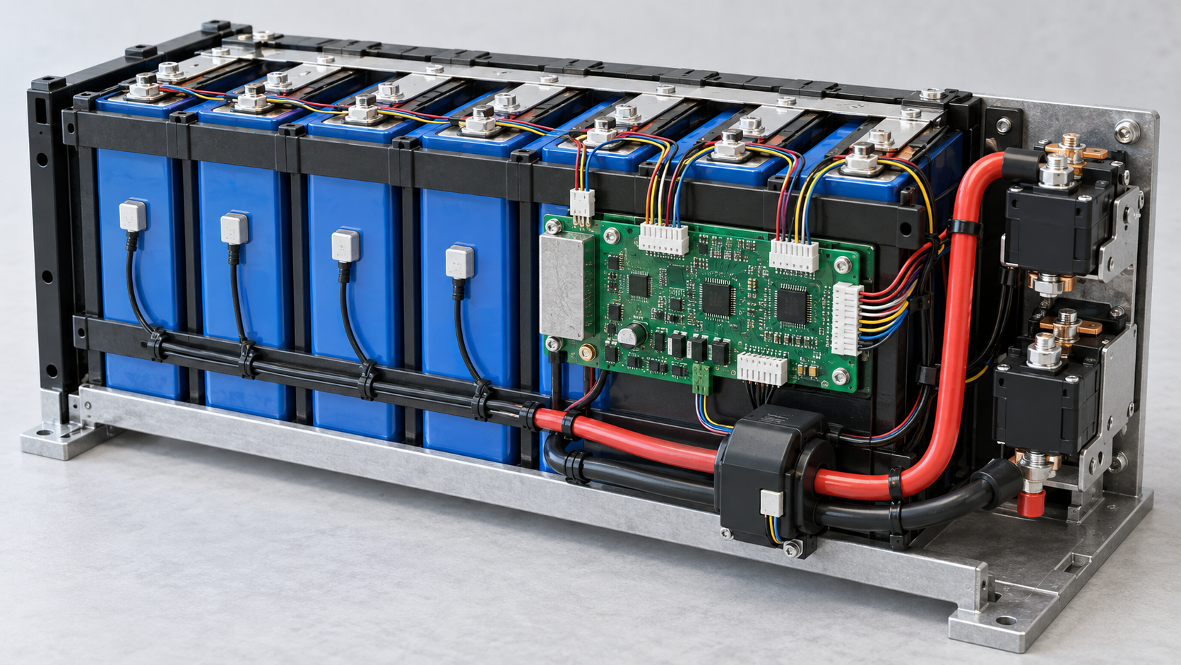
- What a BMS is (the short version)
- What a BMS does — measure, estimate, protect, equalise
- Estimating charge — three ways of thinking
- A materials engineer's view (1): voltage carries the electrode material's quirks (hysteresis)
- A materials engineer's view (2): why LFP's flat voltage makes estimation hard / Our calculation
- Drift in current integration — our calculation
- Estimating aging (SOH)
- Protection and cell balancing — A materials engineer's view (3): material limits behind the set-points
- Functional-safety standards — numbers, titles, scope, status
- What is still hard, and what could not be confirmed
- How to read evaluations and standards
- Glossary
- Primary sources
- Claim-to-source audit
Sourced = a statement in published material (link given)
Our calculation = a figure this article derived, with the assumptions spelled out
Not yet confirmed = a plan or schedule with no confirmed decision or record
Structural readings and materials-design interpretations are marked separately as Commentary. Standards are given with number, title, edition, date and status (current or under revision) kept distinct.
1. What a BMS is (the short version)
- What it does: an electric-vehicle traction battery is a safety-critical electrochemical system whose available energy, power margin, temperature and rate of degradation change with temperature, usage history and manufacturing variation. The BMS is the operational layer that turns limited measurements (terminal voltage, current and a few temperatures) into decisions on power limits, charging, cooling, balancing, isolation and fault responseSourced (Frontiers in Chemistry, 2026)
- Why it is hard: SOC is often called a "fuel gauge", but unlike fuel it cannot be measured directly. Coulomb counting accumulates sensor error, open-circuit-voltage methods need rest, and model-based observers inherit errors in capacity, resistance and temperature dependenceSourced
- What matters to a materials engineer: estimation leans on the electrode material's relation between voltage and charge (the OCV-SOC curve). If the curve is flat (LFP) or moves with history (hysteresis), estimation becomes harder (Commentary)
The accuracy of a BMS is set partly by the voltage characteristics of the electrode material, not only by the algorithm. For a material with a small voltage slope, the same voltage error becomes a much larger charge error. And safety standards mainly address the "malfunction" of the BMS, not the hazards of the battery chemistry itself (Commentary; Chapter 9).
2. What a BMS does — measure, estimate, protect, equalise
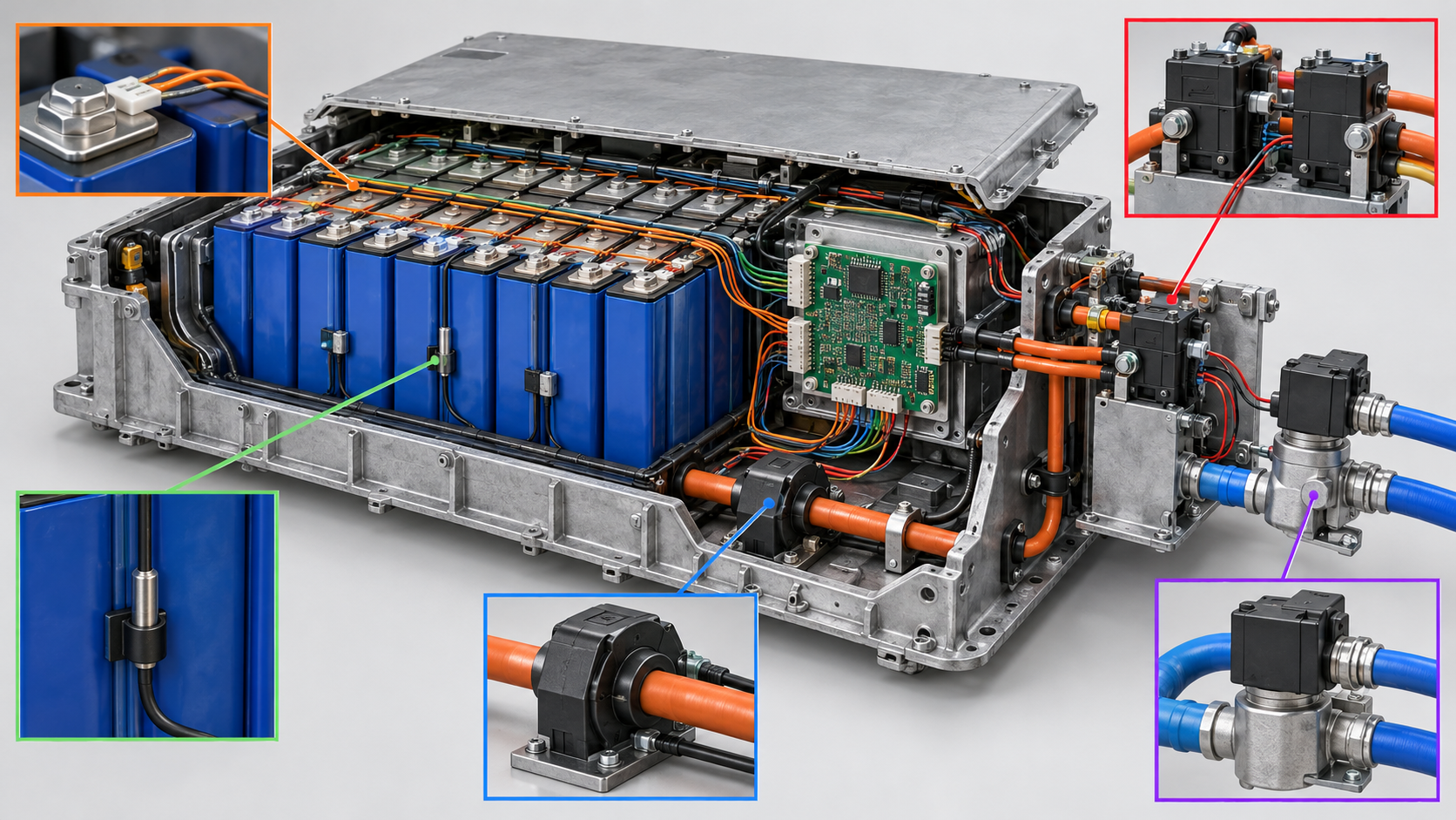
View the original SVG schematic and exact annotations
Li et al. [Source 1] set out the functions of a BMS as followsSourced.
- State estimation: from measurements and parameters, SOC (charge), SOH (aging), SOP (power margin), RUL (remaining life) and their uncertainty are obtained, using adaptive observers, Bayesian filters, neural networks and the like. The problem is that field data labels are limited and domain shift (conditions differing from those learned) is the main cause of failure
- Protection: in the architecture proposed, a deterministic safety-supervisor layer enforces limits on voltage, temperature, lithium plating, power, imbalance and uncertainty before any performance optimisation. Learned updates cannot bypass the certified local safety envelope
- Balancing and charging: because cells vary, the weakest cell, not the pack-average SOC, sets the safe current. Passive balancing is predictable but gives off heat; active balancing can move energy but adds conversion loss, hardware faults and control complexity
Note that the review of Li et al. mainly concerns electric vehicles; stationary and industrial uses may follow different designs and standards (Chapter 9).
3. Estimating charge — three ways of thinking
There are, broadly, three ways to estimate SOC. Each trusts something different and has a different weak point.
| Approach | What it does | Weak point (as stated in the sources) |
|---|---|---|
| Current integration (Coulomb counting) | Measures the terminal current and integrates it to get the charge that has gone in and out | Measurement errors accumulate the longer it is used (Jahn et al.). Sensor bias is integrated (Li et al.). If the capacity in the denominator is fixed while the battery ages, a systematic bias arises, especially near the upper and lower limits (Li et al.) |
| From open-circuit voltage (OCV) | Uses the fact that voltage is a function of charge to read charge from voltage. Used to correct drift in current integration | Needs sufficient rest (Li et al.). OCV also depends on charge-discharge history (hysteresis), and without allowing for it the SOC is wrong (Jahn et al.). Building the OCV-SOC curve itself takes time (Z. Li et al.) |
| Model-based estimation (observers, Kalman filters) | Compares a model such as an equivalent circuit with measurements to estimate internal states and parameters step by step | The model inherits errors in capacity, resistance and temperature dependence (Li et al.). With insufficient excitation, as in constant-current charging or low-current parking, several parameters cannot be determined at once (Z. Li et al.). Accuracy on another dataset alone is not sufficient evidence that a data-driven method is deployable (Li et al.) |
All Sourced (Li et al. [Source 1], Jahn et al. [Source 2], Z. Li et al. (iScience 2025) [Source 3]). The sorting into three is this article's arrangement of what each paper says. Real BMSs combine them (Commentary).
Li et al. state that voltage-only estimators can be accurate on familiar cells but become poorly identifiable when temperature, aging mechanism or chemistry changesSourced. They hold that an effective BMS must be aware of what it can and cannot observe.
4. A materials engineer's view (1): voltage carries the electrode material's quirks (hysteresis)
When OCV is used to correct SOC, the premise is that "OCV is set by SOC alone". Real electrode materials do not behave that way. Jahn et al. (Communications Engineering, 2024) [Source 2] say in their introductionSourced.
- OCV also depends on charge-discharge history; this path dependence is voltage hysteresis. A correct SOC estimate needs to allow for it
- Hysteresis does not disappear even after long relaxation (time with no current)
- The size of the hysteresis depends strongly on the active material: about 10 mV for graphite, up to 20 mV for LFP and more than 200 mV for silicon are pronounced, while LTO (lithium titanate) shows almost none
- The mechanism differs by material too: LFP has a first-order phase transition (two phases, one lithium-poor and one lithium-rich), while silicon has charge-direction-dependent reaction pathways
That the hysteresis of LFP stems from a first-order phase transition will be familiar ground to a materials engineer. Jahn et al. explain that for a material whose Gibbs energy has two minima, giving two stable phases (a lithium-poor and a lithium-rich phase), the electrode potential without phase separation is a non-monotonic function of lithium concentrationSourced. The property of a material that works through a crystal-structure transition shows up as a voltage offset that does not vanish with long rest, which sets a floor on the uncertainty when charge is read from voltage (Commentary).
The point links to our explainer on silicon anodes and nanostructured electrodes. Silicon is said to show hysteresis above 200 mV, so the more capacity a material offers, the more burden it can put on estimation (Commentary). For people designing electrode materials, choosing materials with small hysteresis, or combinations in which hysteresis is predictable, is also a way to reduce the BMS's estimation problem from the material side.
5. A materials engineer's view (2): why LFP's flat voltage makes estimation hard / Our calculation
The OCV method is strongest when a small change in voltage corresponds to a large change in charge. Z. Li et al. (iScience 2025) [Source 3] propose a way to update the OCV-SOC curve during estimation, and state its limitationsSourced.
- The method is applicable only in regions where the OCV-SOC curve is steep. For cells with a flat curve such as LFP, additional constraints are needed
- The complex dynamics at low temperature or low SOC, and the flat OCV-SOC profile of LFP, place significant limits on the method
- The accuracy of equivalent-circuit models is generally high for nickel-cobalt-manganese (NCM) but can be lower for LFP. Modelling accuracy for single cells is also much higher than for packs
SOC error is the voltage uncertainty divided by the slope of the curve (voltage per SOC). With a steep slope, an error of a few millivolts means an error of less than 1% in charge. With a small slope, the same error becomes a charge error larger by an order of magnitude (Commentary). As LFP spreads in stationary storage and in cost-focused electric vehicles, this is a typical case of the choice of material setting the difficulty of system control.
Assumptions Our calculation
- SOC error = voltage uncertainty ÷ slope of the OCV-SOC curve
- Slope: 0.5 mV per % SOC in LFP's flat region and 8 mV per % for nickel-based/graphite cells (both our assumptions: for LFP, 30 mV corresponds to 60% of SOC in the flat region; for nickel-based, about 3.4 to 4.2 V corresponds to 100%, conceptual values)
- Voltage uncertainty: hysteresis uses the literature values given by Jahn et al., up to 20 mV for LFP and about 10 mV for graphiteSourced. Measurement error is taken as ±5 mV (our assumption)
Calculation
- LFP, hysteresis 20 mV: 20 ÷ 0.5 = 40% SOC. Measurement error 5 mV: 5 ÷ 0.5 = 10%
- Nickel-based/graphite, hysteresis 10 mV: 10 ÷ 8 = about 1.3%. Measurement error 5 mV: 5 ÷ 8 = about 0.6%
- Ratio of slopes: 8 ÷ 0.5 = 16 times (the ratio of charge error for the same voltage error)
Reading: in LFP's flat region, deciding SOC from voltage alone can leave a spread of tens of percent from hysteresis (history) alone. For this reason, designs for LFP batteries can be expected to rely mainly on current integration and to correct with voltage where it is usable, such as near the end of charge where the curve rises (Commentary). Assumptions and limits: the slope values are our assumptions; the real slope of an LFP battery's flat region varies with cell, temperature and aging. The ±5 mV measurement error is also assumed and is not the accuracy of a real BMS. What the calculation shows is that the ratio of slopes becomes the ratio of errors.
6. Drift in current integration — our calculation
Current integration can be relied on even where voltage cannot be used, but its weak point is that errors pile up (Chapter 3). Here is the order of magnitude, with assumed numbers.
Assumptions Our calculation
- A pack of 50 Ah capacity whose current sensor has a constant 0.1 A offset (an assumed value)
- Aging has reduced the actual capacity to 40 Ah (SOH 80% of nominal), but the BMS keeps using 50 Ah (an assumed value)
Calculation
- Offset accumulation: 0.1 A ÷ 50 Ah = 0.2% per hour; 2% after 10 hours and 20% after 100 hours (if never corrected)
- Overlooked capacity: when 20 Ah is actually discharged, the BMS estimates a fall of 20 ÷ 50 = 40%, whereas the real fall is 20 ÷ 40 = 50%. The difference is 10 points
Reading: even a small constant offset cannot be ignored as time passes. What Li et al. mean by "capacity must be updated with aging, or a systematic bias arises" is the second item of this calculationSourced. It is also why correction by OCV (re-reading charge from voltage during rest) is needed (Commentary). Assumptions and limits: the 0.1 A offset and the capacities of 50 Ah and 40 Ah are our assumptions, not values of any real sensor or pack.
7. Estimating aging (SOH)
SOH expresses how far a battery has aged. The mechanisms and evaluation of aging itself are covered in our explainer on battery evaluation and degradation; here we set out only why a BMS finds SOH hard to estimate.
- Little can be observed: in the field a BMS gets only voltage, current and a few temperatures. Li et al. say that partial-charge voltage profiles and early-cycle data have been shown to carry features useful for predicting health and lifetime, while EIS (electrochemical impedance spectroscopy) and DRT (distribution of relaxation times) can give low-error SOH features but are limited by hardware, excitation design, identifiability and measurement timeSourced
- Biased data: field data labels are limited and domain shift is a main failure mode. Partial charging and transfer learning make methods more practical but need a mechanism to detect out-of-domain dataSourced
- Recalibration when chemistry changes: the latent states to estimate, the observable electrochemical features, the safe voltage, temperature and pressure envelope and the aging signatures all need recalibrating for each chemistry and cell design, and common numerical parameters or diagnostic thresholds must not be carried over to another chemistry (to avoid negative transfer)Sourced
8. Protection and cell balancing — A materials engineer's view (3): material limits behind the set-points
Many of a BMS's protection set-points (upper and lower voltage limits, temperature range, upper charging current) come from material limits. Here are a few, tied to the content of this series and to primary sources.
| What the BMS protects | The material circumstance behind it | Source |
|---|---|---|
| Lower voltage limit (over-discharge) | Copper current-collector foil can corrode at low voltage. The review explains that formation begins by charging the cell to a relatively low voltage (for example 1.5 V) to protect the copper collector from corrosion | iScience 2021 review [Source 8] |
| Charging current at low temperature and high SOC | At low temperature or high SOC, anode transport and insertion cannot keep up, and lithium plating becomes likely. The BMS's safety supervisor enforces a lithium-plating limit | Li et al. [Source 1] |
| Upper voltage limit (overcharge) | In overcharge tests, even cells with shutdown separators went to internal short circuit and thermal runaway under some test conditions. Safety mechanisms in the cell do not necessarily replace the BMS's cut-off (Commentary) | Orendorff (2012) [Source 9] |
| Variation between cells | The weakest cell sets the end-of-charge voltage margin and the fast-charge current. Equal voltage is not necessarily the right target for cells that differ in capacity and resistance | Li et al. [Source 1] |
All Sourced. The "material circumstance" in each row is this article's matching of the sources' statements. For separators and overcharge, see our explainer on electrolytes and separators.
Li et al. state that the safe envelope of voltage, temperature and pressure must be recalibrated for each chemistry and cell designSourced. Conversely, behind a BMS set-point lie material limits such as the corrosion potential of the current collector, lithium plating on the anode, the decomposition potential of the electrolyte and the heat resistance of the separator (Commentary). Change the material (silicon anodes, sodium-ion, a new electrolyte, for example) and the thresholds change, and the BMS's design and tests have to be redone. This is one reason it takes time for a materials development to reach a battery on the road.
The order of magnitude of passive balancing
Li et al. say passive balancing is predictable but gives off heat, and active balancing can redistribute energy but adds conversion loss, hardware faults and control complexitySourced. Here, with assumed numbers, is how slow passive balancing can be.
Assumptions Our calculation
- Cell voltage 3.3 V and a bleed resistor of 50 Ω (an assumed value)
- A 100 Ah cell has been charged 2% (2 Ah) more than the others (an assumed value)
Calculation
- Current: 3.3 V ÷ 50 Ω = 66 mA. Heat: 3.3 V × 0.066 A = about 0.22 W
- 2 Ah ÷ 0.066 A = about 30 hours
Reading: passive balancing discards heat at a small current, so resolving a large capacity gap takes a long time. The heat appears on the board near the cells (Commentary). Assumptions and limits: the resistance, capacity and gap are all our assumptions and do not show the circuit or operation (balancing current, operating periods) of any real BMS.
9. Functional-safety standards — numbers, titles, scope, status
The standards that bear on the safety of a BMS fall into several layers. Here we list only those whose number, title, edition, date, scope and status could be confirmed on the official pages. Because the full texts are paid, the specific requirements each standard places on a BMS were not checked in this article.
| Standard (number and title) | Edition, date, status | Scope (as stated on the official page) |
|---|---|---|
| IEC 61508-1:2010 Functional safety of electrical/electronic/programmable electronic safety-related systems — Part 1: General requirements | Edition 2.0, 30 April 2010 (replaces the first edition of 1998) | Covers aspects to consider when E/E/PE systems are used to carry out safety functions. Its main objective is to help develop product and application-sector international standards; a second is to enable development of safety-related systems where no sector standard exists |
| ISO 26262-1:2018 Road vehicles — Functional safety — Part 1: Vocabulary | Edition 2, December 2018 (published) | Applies to safety-related systems including electrical and/or electronic (E/E) systems installed in series-production road vehicles (excluding mopeds). It addresses hazards caused by malfunctioning behaviour of safety-related E/E systems and does not address hazards such as electric shock, fire, smoke, heat, toxicity, flammability, corrosion or release of energy unless directly caused by malfunctioning behaviour of safety-related E/E systems |
| ISO 6469-1:2019 Electrically propelled road vehicles — Safety specifications — Part 1: Rechargeable energy storage system (RESS) | Edition 3, April 2019 (current). Amd 1:2022 "Safety management of thermal propagation". Stage: to be revised. The next version, ISO/DIS 6469-1, is a draft (checked on 10 October 2026) | Specifies safety requirements for rechargeable energy storage systems (RESS) of electrically propelled road vehicles for the protection of persons. It does not provide comprehensive safety information for manufacturing, maintenance and repair |
| IEC 62619:2022 Secondary cells and batteries containing alkaline or other non-acid electrolytes — Safety requirements for secondary lithium cells and batteries, for use in industrial applications | Edition 2.0, 24 May 2022 (current; stability date 2026) | Specifies requirements and tests for the safe operation of secondary lithium cells and batteries in industrial applications, including stationary ones. Where another IEC standard for special applications, such as the IEC 62660 series for road vehicles, conflicts with it, that standard takes precedence |
All Sourced (official pages of IEC 61508-1 [Source 7], ISO 26262-1 [Source 4], ISO 6469-1 [Source 5] and IEC 62619 [Source 6]). They show the existence and scope of the standards and are not statements that any BMS design conforms to them.
As the scope statement of ISO 26262-1 shows, what a functional-safety standard addresses is the hazards created by the "malfunction" of safety-related electrical and electronic systems. In a BMS, this means, for example, that a wrong SOC estimate or a failed sensor leaves overcharge or overheating protection inactive. The hazards of thermal runaway and fire that the battery's materials carry are, unless directly caused by malfunction, outside the scope of that standard (Commentary). Battery safety stacks several separate layers: materials and cell design (see our explainer on thermal runaway and battery safety), pack and vehicle safety specifications (for example the safety management of thermal propagation in ISO 6469-1), and the functional safety of the BMS.
10. What is still hard, and what could not be confirmed
(1) What the standards require of a BMS in specific terms
The full texts of ISO 26262, ISO 6469-1 and IEC 62619 are paid, so the specific requirements on a BMS (extent of diagnostics, fault tolerance time, ASIL allocation and so on) were not checked in this article. Also, how IEC 62619:2022 treats the functional safety of a BMS could not be confirmed from the official page.
(2) The accuracy of real BMSs
Actual figures for the SOC and SOH estimation errors of real electric-vehicle or stationary-storage BMSs could not be confirmed here. The calculations in Chapters 5, 6 and 8 are illustrative examples with assumed numbers.
(3) Other standards and regulations (UL 1973, UN GTR No. 20 and others)
UL 1973 for stationary storage and the United Nations Global Technical Regulation No. 20 on electric-vehicle safety are also relevant, but their number, title and status could not be confirmed on official pages here, so they are not covered.
(4) The standing of the papers
Li et al. (2026) is a mini-review, Jahn et al. (2024) a model paper on voltage hysteresis, and Z. Li et al. (2025) a proposal for identifying the OCV-SOC curve. None of them directly evaluates BMS implementation or conformity to standards. The figures quoted (hysteresis of 10 mV to over 200 mV and so on) are literature values from laboratory measurements.
- A BMS turns terminal voltage, current and a few temperatures into decisions on power limits, charging, cooling, balancing and disconnection. SOC cannot be measured directlySourced
- Three ways of estimating exist (current integration, OCV, models), each with a weak point: accumulating error, the need for rest, insufficient excitationSourced
- Hysteresis is about 10 mV for graphite, up to 20 mV for LFP, over 200 mV for silicon and almost none for LTO. LFP's origin is a first-order phase transitionSourced
- The OCV method is hard to apply to a battery with a flat curve such as LFP. The ratio of slopes (16 times under our assumptions) becomes the ratio of charge errorsOur calculation
- Not updating capacity gives a systematic bias. In an assumed example, with capacity going from 50 to 40 Ah, discharging 20 Ah gives a 10-point differenceOur calculation
- BMS thresholds are shadows of material limits (collector corrosion, lithium plating and so on). A change of material means recalibrationSourced
- Functional-safety standards (ISO 26262 and others) address hazards from the malfunction of E/E systems and not the hazards of battery chemistry itself. ISO 6469-1 is under revisionSourced
11. How to read evaluations and standards
Before comparing which number is larger, align the basis of comparison in the following order. This is an editorial reading checklist, not a set of test conditions or acceptance limits prescribed by a standard.
- 1. What was measured?
- estimation error, detection time, protective action and balancing capability. Check the units and whether the result describes a material, component or complete system.
- 2. Under which conditions?
- temperature, ageing, current history, sensor errors and assumed faults. Treat results under different conditions as separate results before comparing them.
- 3. The comparison trap
- Separate estimation-accuracy tests from functional-safety evaluation under faults.
- 4. What does the standard cover?
- Check the identifier, title, edition and scope in the issuing body’s material. Distinguish test methods, safety, interoperability and management requirements. Naming a standard alone does not establish that a test, conformity assessment or certification has been completed.
Keep a comparison note containing the object, units, conditions, sample count and variation, comparator, standard edition and unresolved points. Do not invent numerical conditions or acceptance limits from a public abstract of a standard.
12. Glossary
- BMS
- Battery management system. Monitors voltage, current and temperature, estimates state, and carries out protection and balancing.
- SOC
- State of charge. The remaining charge as a fraction. It cannot be measured directly.
- SOH
- State of health. A measure of how far a battery has aged.
- SOP
- State of power. The power that can be delivered or accepted at the moment.
- OCV
- Open-circuit voltage. The voltage after the battery has rested with no current flowing.
- Coulomb counting
- Integrating current over time to find the charge that has gone in and out.
- Hysteresis
- A path-dependent effect in which the voltage at the same charge differs after charging and after discharging.
- Kalman filter
- A method that estimates a state step by step using both a model and measurements.
- Cell balancing
- A function that reduces the spread of SOC or voltage among series-connected cells. Passive (dissipating in a resistor) and active (moving energy) types exist.
- Functional safety
- The idea of making sure safety-related electrical and electronic systems do not become dangerous when they malfunction.
- RESS
- Rechargeable energy storage system. The traction battery of an electrified vehicle.
- ASIL
- Automotive safety integrity level. A classification in ISO 26262 according to the size of the hazard (details not checked in this article).
13. Primary sources
- F. Li, Y. Li, W. Wu, H. Qiao, L. Jiang "From state estimation to active intelligence: safety-aware battery management for electric vehicles", Frontiers in Chemistry 14, 1960882 (2026) (mini-review) — pmc.ncbi.nlm.nih.gov
- L. Jahn, P. Mössle, F. Röder, M. A. Danzer (University of Bayreuth) "A physically motivated voltage hysteresis model for lithium-ion batteries using a probability distributed equivalent circuit", Communications Engineering 3, 74 (2024) — pmc.ncbi.nlm.nih.gov
- Z. Li, C. Chen, R. Yang, H. Li, R. Xiong "Entropy-driven online open circuit voltage identification for precise state estimation in lithium-ion batteries", iScience 28(9), 113290 (2025) — pmc.ncbi.nlm.nih.gov
- ISO "ISO 26262-1:2018 Road vehicles — Functional safety — Part 1: Vocabulary" (Edition 2, December 2018) — iso.org
- ISO "ISO 6469-1:2019 Electrically propelled road vehicles — Safety specifications — Part 1: Rechargeable energy storage system (RESS)" (Edition 3, April 2019; Amd 1:2022; ISO/DIS 6469-1 is a draft) — iso.org
- IEC "IEC 62619:2022 Secondary cells and batteries containing alkaline or other non-acid electrolytes — Safety requirements for secondary lithium cells and batteries, for use in industrial applications" (Edition 2.0, 24 May 2022) — webstore.iec.ch
- IEC "IEC 61508-1:2010 Functional safety of electrical/electronic/programmable electronic safety-related systems — Part 1: General requirements" (Edition 2.0, 30 April 2010) — webstore.iec.ch
- Y. Liu, R. Zhang, J. Wang, Y. Wang "Current and future lithium-ion battery manufacturing", iScience 24(4), 102332 (2021) (review) — pmc.ncbi.nlm.nih.gov
- C. J. Orendorff (Sandia National Laboratories) "The Role of Separators in Lithium-Ion Cell Safety", The Electrochemical Society Interface, Summer 2012, 21(2), 61-65 — electrochem.org
14. Claim-to-source audit
| Claim in the text | Basis | Type |
|---|---|---|
| That a traction battery is a safety-critical electrochemical system whose available energy, power, temperature and rate of aging change with temperature, usage, charging and manufacturing variation; that the BMS turns limited measurements (terminal voltage, current and a few temperatures) into decisions on power limits, charging, cooling, balancing, isolation and fault response | Li et al., Frontiers in Chemistry 14, 1960882 (2026)[Source 1] https://pmc.ncbi.nlm.nih.gov/articles/PMC13619866/ | Sourced |
| That SOC cannot be measured directly; that current integration accumulates sensor bias, OCV methods need sufficient rest, and model-based observers inherit errors in capacity, resistance and temperature dependence; that a fixed capacity under aging gives a systematic SOC bias, especially near the upper and lower limits; that voltage-only estimators become poorly identifiable when temperature, aging mechanism or chemistry changes | Li et al. (2026)[Source 1] https://pmc.ncbi.nlm.nih.gov/articles/PMC13619866/ | Sourced |
| The description of BMS functions: estimation of SOC, SOH, SOP, RUL and uncertainty (adaptive observers, Bayesian filters, neural networks and so on); that field data labels are limited and domain shift is the main failure mode; that a deterministic safety-supervisor layer enforces limits on voltage, temperature, lithium plating, power, imbalance and uncertainty before performance optimisation; that learned updates cannot bypass the certified local safety envelope | Li et al. (2026)[Source 1] https://pmc.ncbi.nlm.nih.gov/articles/PMC13619866/ | Sourced |
| That the weakest cell, not the pack-average SOC, sets the safe current and the end-of-charge margin; that passive balancing is predictable but dissipates heat while active balancing adds conversion loss, hardware faults and control complexity; that equal voltage is not necessarily the right target for cells with different capacity and resistance; that lithium plating is likely at low temperature or high SOC | Li et al. (2026)[Source 1] https://pmc.ncbi.nlm.nih.gov/articles/PMC13619866/ | Sourced |
| On SOH estimation: that partial-charge voltage profiles and early-cycle data carry features; that EIS and DRT can give low-error SOH features but are limited by hardware, excitation design, identifiability and measurement time; that partial charging and transfer learning need out-of-domain detection; that recalibration is needed for each chemistry and cell design and common thresholds must not be carried over | Li et al. (2026)[Source 1] https://pmc.ncbi.nlm.nih.gov/articles/PMC13619866/ | Sourced |
| That SOC is often found by Coulomb counting, whose measurement errors accumulate; that OCV depends on charge-discharge history (voltage hysteresis), which must be allowed for; that hysteresis does not vanish after long relaxation; that its size is about 10 mV for graphite, up to 20 mV for LFP, over 200 mV for silicon and negligible for LTO; that the LFP mechanism is a first-order phase transition; the two minima of the Gibbs energy and the two stable phases (lithium-poor and lithium-rich) | Jahn et al., Communications Engineering 3, 74 (2024)[Source 2] https://pmc.ncbi.nlm.nih.gov/articles/PMC11139865/ | Sourced |
| That building the OCV-SOC curve is a time-consuming test; that EKF and forgetting-factor recursive least squares are representative online identification methods; that parameters cannot be determined together without sufficient excitation, as in constant-current charging or low-current parking; that the proposed method applies only where the OCV-SOC curve is steep and a flat curve such as LFP needs additional constraints; that equivalent-circuit accuracy is generally high for NCM and may be lower for LFP, and higher for single cells than for packs | Z. Li et al., iScience 28(9), 113290 (2025)[Source 3] https://pmc.ncbi.nlm.nih.gov/articles/PMC12496173/ | Sourced |
| That ISO 26262-1:2018 (Road vehicles - Functional safety - Part 1: Vocabulary) is Edition 2 (December 2018), applies to safety-related systems including E/E systems in series-production road vehicles (excluding mopeds), addresses hazards caused by malfunctioning behaviour of safety-related E/E systems, and does not address electric shock, fire, smoke, heat, toxicity, flammability, corrosion, release of energy and similar hazards unless directly caused by such malfunction | ISO official page[Source 4] https://www.iso.org/standard/68383.html | Sourced |
| That ISO 6469-1:2019 (Electrically propelled road vehicles - Safety specifications - Part 1: RESS) is Edition 3 (April 2019) and specifies safety requirements for RESS for the protection of persons; that Amd 1:2022 is "Safety management of thermal propagation"; that its stage is "to be revised" and that ISO/DIS 6469-1 is a draft (checked on 10 October 2026) | ISO official page[Source 5] https://www.iso.org/standard/68665.html | Sourced |
| That IEC 62619:2022 is Edition 2.0 (24 May 2022), specifies requirements and tests for the safe operation of secondary lithium cells and batteries in industrial applications including stationary ones, and gives precedence to standards for special applications such as the IEC 62660 series for road vehicles; that its stability date is 2026; that the official page does not mention functional safety of a BMS | IEC Webstore[Source 6] https://webstore.iec.ch/en/publication/64073 | Sourced |
| That IEC 61508-1:2010 (Functional safety of electrical/electronic/programmable electronic safety-related systems - Part 1: General requirements) is Edition 2.0 (30 April 2010, replacing the 1998 first edition) and has as its main objective helping to develop sector and application standards | IEC Webstore (abstract)[Source 7] https://webstore.iec.ch/en/publication/5515 | Sourced |
| That formation begins by charging to a relatively low voltage (for example 1.5 V) to protect the copper current collector from corrosion | iScience 2021 review (Liu et al.)[Source 8] https://pmc.ncbi.nlm.nih.gov/articles/PMC8050716/ | Sourced |
| That, in overcharge tests, cells with shutdown separators went to internal short circuit and thermal runaway under some test conditions (voltage limit, charge rate) | Orendorff, ECS Interface 21(2) (2012)[Source 9] https://www.electrochem.org/dl/interface/sum/sum12/sum12_p061_065.pdf | Sourced |
| That with assumed slopes of 0.5 mV per % in LFP's flat region and 8 mV per % for nickel-based/graphite cells, hysteresis of 20 mV and 10 mV and an assumed measurement error of 5 mV give SOC errors of 40% and 10% (LFP) and about 1.3% and about 0.6% (nickel-based); that the ratio of slopes is 16 times | Our calculation. The slopes and the +/-5 mV measurement error are our assumptions. The hysteresis of 20 mV and about 10 mV are literature values from Jahn et al. Not the accuracy of a real BMS | Our calculation |
| That a 0.1 A offset on a 50 Ah capacity gives 0.2% per hour (2% after 10 hours, 20% after 100 hours); that a capacity falling from 50 to 40 Ah but still taken as 50 Ah gives an estimated 40% fall against an actual 50% fall when 20 Ah is discharged, a difference of 10 points | Our calculation. The 0.1 A, 50 Ah and 40 Ah are our assumptions, not values of a real sensor or pack | Our calculation |
| That 3.3 V across 50 Ω gives 66 mA (about 0.22 W) and that resolving a 2 Ah difference takes about 30 hours | Our calculation. The resistance, capacity and difference are our assumptions and do not show the circuit or operation of a real BMS | Our calculation |
| The sorting of the three estimation approaches; the reading that hysteresis sets a floor on the uncertainty when charge is read from voltage; the relation between silicon's hysteresis and capacity; the reading that LFP designs rely mainly on current integration and correct with voltage where it rises; that the choice of material sets the difficulty of system control; that BMS thresholds are shadows of material limits; that functional safety addresses the hazards of E/E malfunction and not the hazards of battery chemistry itself; that battery safety stacks three layers (materials and cell, pack and vehicle, BMS) | Commentary by this article | Commentary |
| The specific requirements of each standard on a BMS (extent of diagnostics, fault tolerance time, ASIL allocation and so on), the treatment of BMS functional safety in IEC 62619:2022, UL 1973 and UN GTR No. 20, and the estimation accuracy of real BMSs | Could not be confirmed in published primary sources within the scope of this article, so not stated (standard texts are paid) | Commentary |
| That Figs. 2 to 5 and 7 are explanatory drawings rather than real BMS or battery structures or measurements, and that Figs. 1 and 6 are AI-generated images | Our note | Commentary |
Last updated 10 October 2026. Sources are limited to primary material (peer-reviewed papers and reviews, and the official pages of ISO and IEC). Because the article includes structural readings and materials-design interpretations, those are marked as Commentary and kept separate from sourced fact. The specific requirements the standards place on a BMS, the estimation accuracy of real BMSs, and UL 1973 and UN GTR No. 20 could not be confirmed in published primary sources and are not stated. The status of the standards (current or under revision) was checked on the pages of each body on 10 October 2026 and changes when a revision appears. The calculations in Chapters 5, 6 and 8 are illustrative examples with assumptions of our own, not measurements and not the accuracy of any real BMS. All figures are explanatory concept graphics. Figs. 2 to 5 and 7 are vector drawings; Figs. 1 and 6 are AI-generated images, and none of them shows a real battery, BMS or test result.