TECHNOLOGY EXPLAINER
What the Coefficient of Thermal Expansion Is
— nearly every back-end defect starts here
The same phrase turns up in every article in this series: CTE mismatch. Underfill, glass substrates, build-up film — all of them end up at those two words. This article takes on CTE itself, head on.
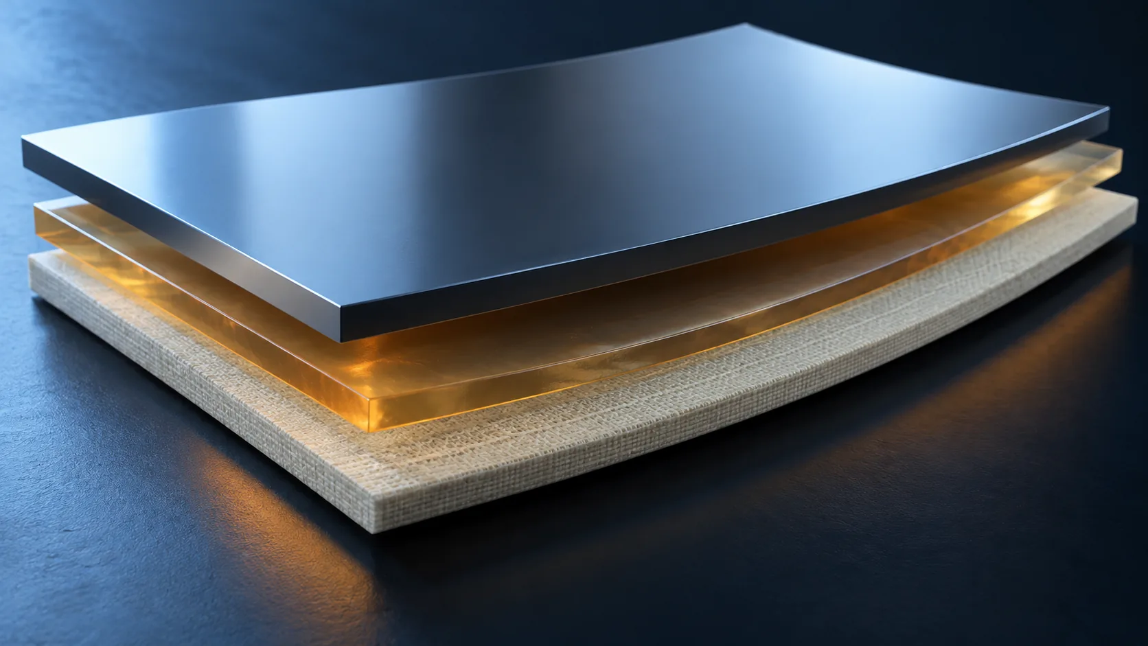
- What the coefficient of thermal expansion is (the short version)
- Why it becomes a serious problem only in back-end assembly
- In numbers — how far apart real materials actually are
- A materials engineer's view 1: how many micrometres is the mismatch?
- A materials engineer's view 2: CTE is not one number
- A materials engineer's view 3: lower is not simply better
- How to fight it — break one of the three stress terms
- What is still hard / Glossary / Primary sources / Claim-to-source audit
Sourced = content stated in a company's published material (link given)
Our calculation = a figure this article derived, with the assumptions spelled out
Not yet confirmed = work at development stage with no confirmed production record
Beyond those, structural framing and readings about materials design are marked Commentary.
1. What the coefficient of thermal expansion is (the short version)
- CTE is the number that says what fraction a material grows by when the temperature rises one degree. The unit is ppm/°C, parts per million.
- What causes trouble is not the absolute value but the difference. Join two materials with different CTE and every temperature change sets up a tug of war.
- Back-end assembly is one trip up to 260 °C and back to room temperature after another. So a CTE mismatch always turns into stress.
A feel for the numbers first. A material with a CTE of 10 ppm/°C grows in length by 1,000 ppm, that is 0.1 %, when the temperature rises 100 °C. On a 40 mm substrate edge that is 40 µm: about half the diameter of a human hair.
On its own that would hardly matter. The problem is that the material next to it grows by a different amount.
2. Why it becomes a serious problem only in back-end assembly
Kyocera writes this on its ceramic package technology page: "During mounting, a large difference in coefficient of thermal expansion between materials causes thermal stress under heating and cooling, leading to problems such as fracture of the mounted joint. To relieve thermal stress and improve device reliability, it is important to bring the coefficients of thermal expansion of device and package, and of package and motherboard, closer together"Sourced.
Resonac describes the same problem in advanced packages: "In advanced semiconductor packages that stack dissimilar materials with different CTE, the differential shrinkage of each material arising from the thermal history of the manufacturing process becomes a cause of warpage at a level that cannot be ignored for design accuracy." And that, it says, is "a problem that leads directly to connection failures and shortened product life"Sourced.
A CTE mismatch only bites when the temperature changes. And back-end assembly is one heating and cooling step after another. Here are the ones this series has covered.
- Solder reflow: Resonac's CCL carries "solder heat resistance (260 °C)" as a specification itemSourced
- Encapsulant cure: as the Underfill and Encapsulants article showed, cure temperature and Tg set the properties
- Build-up layer cure: Resonac cites "low-temperature cure at around 200 °C" for photosensitive polyimide as a means of suppressing warpageSourced
- Underfill cure: Kyocera gives "150 °C to 20 °C (underfill cure condition)" as its stress analysis conditionSourced
Front-end wafer processing has high-temperature steps too, but what it handles there is almost entirely silicon. The moment you enter back-end assembly, silicon, copper, resin, glass and ceramic share the same board. CTE mismatch is a back-end problem because back-end assembly is the world of dissimilar materials (Commentary).
3. In numbers — how far apart real materials actually are
What follows is nothing but published numbers. Not estimates or generalities, but values the makers print in their cataloguesSourced.
| Material / product | CTE | Conditions and notes | Source |
|---|---|---|---|
| LTCC "GL570" (Kyocera) | 3.4 ppm/K | RT to 400 °C. "Developed as a material with a coefficient of thermal expansion close to Si" / for advanced semiconductors | Kyocera [1][2] |
| Aluminium nitride "AN242" (Kyocera) | 4.7 ppm/K | RT to 400 °C. Thermal conductivity 150 W/m·K | Kyocera [2] |
| Alumina "A440" (Kyocera) | 7.1 ppm/K | RT to 400 °C. "Most general-purpose" / thermal conductivity 14 W/m·K | Kyocera [2] |
| LTCC "GL773" (Kyocera) | 11.7 ppm/K | RT to 400 °C. "Good second-level assembly" / for advanced semiconductors | Kyocera [2] |
| Inorganic core substrate (Nippon Electric Glass) | 6.1 to 8.9 ppm/°C | Several types. Flexural strength 150 to 340 MPa | Nippon Electric Glass [5] |
| Copper-clad laminate "MCL-E-795G" in-plane (X and Y) (Resonac) | 3.0 to 5.0 ppm/°C (LH type 0.5 to 3.0) | 30 to 120 °C. Inner-layer core material for build-up | Resonac [4] |
| Same, through-thickness (Z) | 10 to 15 ppm/°C (below Tg) 70 to 100 ppm/°C (above Tg) | Tg = 260 to 290 °C (TMA method) | Resonac [4] |
| Four interlayer dielectric films (Sekisui Chemical) | 15 to 27 ppm/°C | 25 to 150 °C. NX04H = 24.5 / NQ07V = 27 / QX04 = 15 / EL = 17 to 23 | Sekisui Chemical [6] |
| Epoxy encapsulant for organic substrates (Resonac) | alpha-1 6 to 12 ppm/°C alpha-2 27 to 45 ppm/°C | alpha-1 below Tg, alpha-2 above. Tg 120 to 155 °C | Resonac [7] |
| Granular EMC "CEL-400ZHF40" (Resonac) | 10 ppm/°C or less | "Combines low thermal expansion of 10 ppm/°C or less with a low modulus of 20 GPa or less" | Resonac [8] |
All figures are the companies' published values (representative or measured). Measurement temperature ranges and methods differ from company to company, so the numbers in this table cannot be compared directly with one another. Kyocera uses RT to 400 °C, Resonac's CCL 30 to 120 °C, Sekisui Chemical 25 to 150 °C.
Inside one package, a material at 0.5 ppm/°C sits next to a material at 45 ppm/°C — that is what the chart means. A spread of about ninety times.
And notice that most of that spread is occupied by the resin-based materials. Ceramics and glass stay inside a narrow 3 to 12 ppm/K band, while materials built on resin (interlayer films, encapsulants) fan out across 15 to 45 ppm/°C.
Turn that round and it says resin-based materials let you design the CTE through the type, amount and dispersion of filler (Commentary). Sekisui Chemical's four products differ nearly twofold in CTE, 15 to 27 ppm/°C, and yet they are one product family of "thermally cured interlayer dielectric film"Sourced. CTE is not a material's fate. It is a design variable.
4. A materials engineer's view 1: how many micrometres is the mismatch?
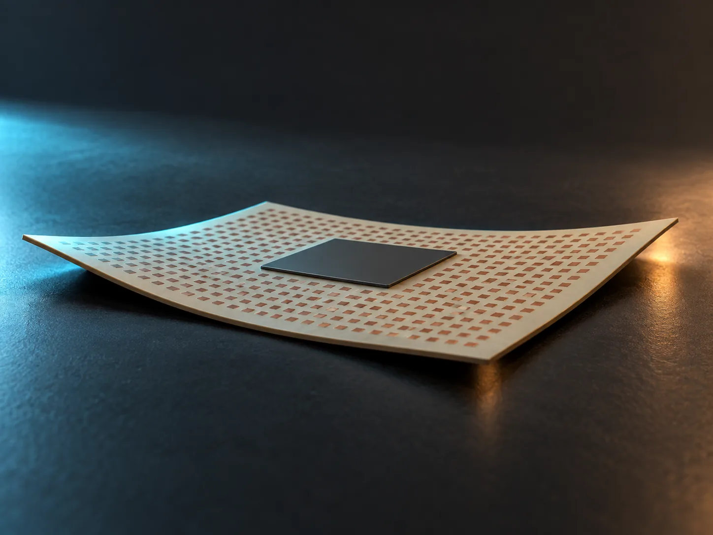
Every source says CTE mismatch is a problem. What they rarely say is how many micrometres that actually is. So let us work it out.
Borrowing the TEG conditions Resonac uses for warpage evaluation: chip 20 mm × 20 mm, substrate 40 mm × 40 mmSourced.
Assumptions:
- Temperature change 235 °C (cooling from a 260 °C solder reflow to 25 °C)
- Silicon CTE taken as 3.4 ppm/°C, borrowed from Kyocera calling its 3.4 ppm/K LTCC "GL570" "a material with a coefficient of thermal expansion close to Si"Sourced
- The other side is Sekisui Chemical's interlayer film "NX04H" at 24.5 ppm/°CSourced
- The chip centre is the fixed point, and the mismatch is evaluated from centre to edge, 10 mm
- The calculation assumes free expansion (in reality the parts constrain each other)
Working:
- CTE gap = 24.5 − 3.4 = 21.1 ppm/°C
- Displacement = 10 mm × 21.1 ppm/°C × 235 °C = 10 mm × 0.00496
- = 0.0496 mm = about 50 µm
Now try it with a low-expansion copper-clad laminate. The in-plane CTE of Resonac's "MCL-E-795G" is 3.0 to 5.0 ppm/°C (LH type 0.5 to 3.0)Sourced. Taking the lower bound of 3.0 ppm/°C:
- CTE gap = 3.4 − 3.0 = 0.4 ppm/°C
- Displacement = 10 mm × 0.4 ppm/°C × 235 °C = 0.00094 mm = about 0.9 µm
About 50 µm against about 0.9 µm. More than a factor of fifty.
A caution: an interlayer film and a core material do not play the same role or sit in the same place inside a package. This calculation does not say one can be substituted for the other; it is there to give a feel for the dimensional consequence of a CTE gap. It also assumes free expansion, and because real parts constrain each other, most of this mismatch turns into stress rather than displacement.
Set that 50 µm against the other articles in this series.
- Bumps: copper pillar bumps live at pitches of a few tens of µm
- Hybrid Bonding: imec has demonstrated bonding at 400 nm and then 200 nm pitch
- Silicon Photonics: for optical fibre coupling, positional accuracy is loss
A force wanting to move things 50 µm is acting on joints pitched a few tens of µm apart. That is what the back-end "CTE problem" really is. Why underfill is needed, and why low-expansion substrate materials keep being developed, both come back to this one point (Commentary).
5. A materials engineer's view 2: CTE is not one number
When a datasheet says "CTE 20 ppm/°C", in which direction, over what temperature range, and when? Without an answer, the number is unusable.
The datasheet for Resonac's copper-clad laminate "MCL-E-795G" makes the point vividlySourced.
The LH type of "MCL-E-795G" runs 0.5 to 3.0 ppm/°C in plane — lower than silicon. And yet through the thickness, above Tg, it is 70 to 100 ppm/°CSourced.
One and the same board expands up to two hundred times differently depending on direction and temperatureOur calculation (the ratio of 0.5 ppm/°C to 100 ppm/°C, dividing a published lower bound by a published upper bound; these were not measured simultaneously on one sample).
Why? The glass cloth. In plane, the glass fibres restrain the expansion, so the value is low; through the thickness there are no fibres, so you see the resin's own value. When Resonac writes that "combining it with low-expansion glass cloth realises an even lower coefficient of thermal expansion for MCL-E-795G (LH type)", it is talking about exactly this structureSourced.
The CTE of a resin-based material is set not by the resin's own properties but by what is restraining it — familiar ground for anyone who works with fibre-reinforced composites, but easy to overlook when the same principle turns up in semiconductor packaging (Commentary).
What "alpha-1" and "alpha-2" are telling you
As the Underfill and Encapsulants article noted, the CTE of a resin changes discontinuously at the glass transition temperature. Resonac publishes alpha-1 6 to 12, alpha-2 27 to 45 ppm/°C, Tg 120 to 155 °C for its epoxy encapsulant for organic substratesSourced. Above Tg it is three to four times greater.
The awkward part is that back-end temperatures straddle exactly that Tg. Solder reflow is 260 °C. With an encapsulant Tg of 120 to 155 °C, reflow is always in alpha-2 territory. The CCL's Tg is 260 to 290 °C (TMA method), so that one sits on the boundary around reflow temperatureSourced.
- What temperature range? Kyocera RT to 400 °C, Resonac's CCL 30 to 120 °C, Sekisui Chemical 25 to 150 °C. Different ranges cannot be comparedSourced
- Which direction? In plane (X, Y) or through thickness (Z). Resonac even states the method: "X, Y in tension, Z in compression"Sourced
- Above or below Tg? Alpha-1 or alpha-2. If your service temperature crosses Tg you need both
- Which measurement method? For the same material, Tg itself comes out as 260 to 290 °C by TMA and 315 to 345 °C by DMASourced
- Representative, measured or guaranteed? Kyocera says "representative values"; Resonac states "the above are measured values and not guaranteed values"Sourced
6. A materials engineer's view 3: lower is not simply better
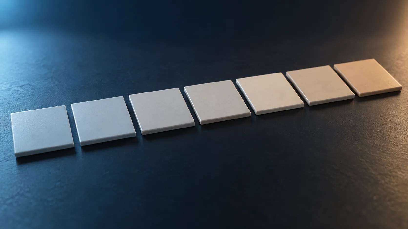
Read this far and "lower CTE is better" starts to feel right. It is not.
In its multilayer ceramics property table, Kyocera publishes LTCC "GL570" at 3.4 ppm/K and LTCC "GL773" at 11.7 ppm/K. Both are for advanced semiconductors. GL570's headline feature is "good first-level assembly", GL773's is "good second-level assembly"Sourced.
And Kyocera explains: "Kyocera offers a broad line-up of materials with coefficients of thermal expansion ranging from close to Si to close to the motherboard"Sourced.
What the existence of those two products says is that CTE has no "good direction".
- On the face that meets the chip, match silicon (go lower)
- On the face that meets the motherboard, match the PCB (go higher)
- The package carries both at once
So materials development for advanced packages is not a race to lower CTE but a race to hit a target value. And the target differs with where the material goes. That Resonac's CCL comes in standard, X and LH grades, and that Sekisui Chemical's interlayer films span 15 to 27 ppm/°C, are the same thingSourced.
This is where a materials supplier competes. A competitor can also hit any one value. The difference is whether you can produce several values on one line, at one quality (Commentary).
The verification Kyocera publishes
Kyocera also publishes a simulation check of the idea. Running a stress analysis over 150 °C to 20 °C (an underfill cure condition) for alumina "A440" and for LTCC "GL570", whose CTE is close to Si, it states that it "confirmed reduced substrate warpage for the GL570 substrate, whose coefficient of thermal expansion is close to that of the silicon interposer"Sourced.
Alumina's CTE is 7.1 ppm/K, GL570's is 3.4 ppm/KSourced. Halving it, from 7.1 to 3.4, reduced the warpage — and while it matters that this is an analysis rather than a measurement, it is one of the few public examples where the effect of CTE matching is shown quantitatively (Commentary).
7. How to fight it — break one of the three stress terms
Reducing the CTE gap to zero would be best. In practice it cannot be done: silicon and resin cannot be given the same CTE.
So materials makers work instead on making the thermal stress itself smaller. Thermal stress is, roughly, the product of three things.
Resonac's granular EMC "CEL-400ZHF40" is described as "combining low thermal expansion of 10 ppm/°C or less with a low modulus of 20 GPa or less"Sourced. Let us estimate what that combination buys, using the simplified expressionOur calculation.
Assumptions: thermal stress = modulus × CTE gap × temperature swing. Silicon CTE 3.4 ppm/°C, temperature swing 235 °C (260 °C to 25 °C).
- Improved (CTE 10, E 20 GPa): 20,000 MPa × (10 − 3.4) ppm/°C × 235 °C = about 31 MPa
- For comparison (CTE 20, E 30 GPa, assumed): 30,000 MPa × (20 − 3.4) ppm/°C × 235 °C = about 117 MPa
- Ratio = about one quarter
On top of that, Resonac says of its photosensitive polyimide that it "can be cured at low temperature, around 200 °C, keeping the differential shrinkage between materials from thermal history to a minimum and suppressing warpage of the semiconductor package"Sourced. Drop the cure temperature from 260 °C to 200 °C and the swing goes from 235 °C to 175 °C. That alone works out at about 25% less stressOur calculation.
Assumptions and limits: the "for comparison" figures of CTE 20 ppm/°C and E 30 GPa are values this article assumed; they do not refer to any particular earlier product. The expression is a simplified relationship showing a trend, and real stress depends strongly on geometry, constraint and the viscoelasticity of the resin. It is not an expression you can design with.
Re-sorting the materials technologies from across this series into those three buckets makes the landscape clearer (our own framing).
- 1 Shrink the CTE gap: low-expansion CCL, glass core substrates, high loading of low-CTE filler, low-expansion glass cloth
- 2 Lower the modulus: low-modulus encapsulant, underfill, stress relief layers
- 3 Shrink the temperature swing: low-temperature cure materials, low-temperature solder, revisiting process temperatures
What is interesting is that 1 and 2 collide head on. The standard way to lower CTE is heavy loading of inorganic filler, but more filler raises the modulus. Resonac's phrasing, low expansion of 10 ppm/°C or less and a low modulus of 20 GPa or less combined, is a claim to have resolved that collision (Commentary).
Which is why 3, shrinking the temperature swing, matters so much. It is the only lever that reduces stress without touching the material's properties. That is why low-temperature cure and low-temperature processing come up again and again in advanced packaging (Commentary).
8. What is still hard
Problem 1: match the CTE and you lose something else
Kyocera's property table shows the price plainly. Put the Si-matched LTCC "GL570" next to the general-purpose alumina "A440"Sourced.
| Property | GL570 (LTCC) | GL773 (LTCC) | A440 (alumina) | AN242 (AlN) |
|---|---|---|---|---|
| CTE (RT to 400 °C) | 3.4 ppm/K | 11.7 ppm/K | 7.1 ppm/K | 4.7 ppm/K |
| Thermal conductivity | 2.8 W/m·K | 1.9 W/m·K | 14 W/m·K | 150 W/m·K |
| Three-point flexural strength | 200 MPa | 280 MPa | 400 MPa | 400 MPa |
| Young's modulus | 128 GPa | 95 GPa | 310 GPa | 320 GPa |
| Dielectric constant (1 MHz) | 5.6 | 5.7 | 9.8 | 8.7 |
| Headline feature (published) | Advanced semiconductors / good first-level assembly | Advanced semiconductors / good second-level assembly | Most general-purpose | High thermal conductivity |
All figures are Kyocera's published representative values [Source 2].
GL570, brought close to Si in CTE, has one fifth the thermal conductivity of alumina and about one fifty-fourth that of AlN. Its flexural strength is halfOur calculation (dividing published values: 2.8 / 14 = 0.2, 2.8 / 150 = 0.019, 200 / 400 = 0.5).
Scanning Kyocera's table, a tendency shows up: the lower the CTE, the lower the thermal conductivity (GL570 = 3.4 / 2.8, GL773 = 11.7 / 1.9, A440 = 7.1 / 14). That said, this is a tendency across four materials, not a general law (this article's reading).
AlN combining CTE 4.7 ppm/K with thermal conductivity 150 W/m·K can be read as valuable precisely because it is an exception to that tendency (Commentary).
Which is why selecting a material on CTE alone will always fail. The heat-dissipation and flow requirements from the Underfill and Encapsulants article and the warpage requirement from this one compete for the same material (Commentary).
Problem 2: the bigger the package, the larger the mismatch, in proportion
The calculation in Section 4 showed that displacement is proportional to distance. A 20 mm chip gives about 50 µm. So where are advanced packages heading?
Same assumptions as Section 4 (CTE gap 21.1 ppm/°C, swing 235 °C, free expansion), changing only the distance evaluatedOur calculation.
- 10 mm from centre (20 mm square): about 50 µm
- 25 mm from centre (50 mm square): about 124 µm
- 50 mm from centre (100 mm square): about 248 µm
Assumptions: the same simplified free-expansion calculation as Section 4. Constraint, warpage and viscoelasticity mean reality will not follow it. The numbers exist only to show that growing larger worsens the warpage problem linearly.
As the CoWoS, PLP and Glass Substrate articles showed, advanced packages are heading toward larger formats. Larger formats will certainly make the CTE problem worse. One reason glass core substrates draw attention is what Nippon Electric Glass calls "reduced dimensional change and warpage under high temperature and high humidity"Sourced — the same context.
Problem 3: measurement conditions are not aligned
The hardest part of writing this article was that the numbers cannot be compared.
- Kyocera: RT to 400 °C
- Resonac (CCL): 30 to 120 °C, X and Y in tension, Z in compression, heating rate 10 °C/min
- Sekisui Chemical: 25 to 150 °C
- Resonac (encapsulant): split into alpha-1 and alpha-2
Each company is honest about stating its conditions, but different conditions mean no side-by-side comparison. That is why Figs. 2 and 5 in this article carry the note "for a sense of order of magnitude". How far standardisation of measurement conditions will go is not visible from hereNot yet confirmed.
- A CTE mismatch is the starting point of nearly every back-end defect. Kyocera: "to relieve thermal stress and improve device reliability, it is important to bring the coefficients of thermal expansion of device and package, and of package and motherboard, closer together"Sourced
- The edge of a 20 mm chip wants to move about 50 µm (with a CTE gap of 21.1 ppm/°C and a swing of 235 °C)Our calculation
- CTE is not one number. The same copper-clad laminate is 0.5 to 3.0 in plane and 70 to 100 ppm/°C through thickness above TgSourced
- Lower is not better. Kyocera builds 3.4 and 11.7 within one LTCC familySourced
- There are three ways to fight: shrink the CTE gap, lower the modulus, shrink the temperature swing (our own framing)
- Match the CTE and you lose something else. GL570's thermal conductivity is 2.8 W/m·K, one fifth of alumina'sSourced
9. Glossary
- CTE
- Coefficient of Thermal Expansion. The fractional change in dimension per degree, in ppm/°C or ppm/K.
- ppm
- Parts per million. A material at 10 ppm/°C grows 0.1 % over a 100 °C rise.
- Thermal stress
- Stress set up inside a material by a temperature change, arising when materials of different CTE constrain each other.
- Warpage
- Deformation that leaves a package or substrate no longer flat. Differential shrinkage from CTE mismatch is a leading cause.
- Tg
- Glass transition temperature, where a resin moves from glassy to rubbery. CTE changes sharply across it.
- alpha-1 and alpha-2
- CTE below Tg (alpha-1) and above Tg (alpha-2). Resin materials quote the two separately.
- TMA and DMA
- Methods for measuring Tg: thermomechanical analysis and dynamic mechanical analysis. The same material gives different values.
- In plane / through thickness
- The directions a sheet spreads in (X, Y) and its thickness direction (Z). In fibre-reinforced material the two CTEs differ greatly.
- CCL
- Copper Clad Laminate. The copper-faced board that forms the foundation of a substrate.
- Prepreg
- Glass cloth impregnated with resin and left partly cured. Laminated up to make a substrate.
- Glass cloth
- Woven glass fibre. It forms the substrate's skeleton and restrains in-plane expansion.
- LTCC
- Low Temperature Co-fired Ceramics, which allow copper conductors.
- First-level / second-level assembly
- Mounting the chip on the package (first level) and the package on the motherboard (second level).
- EMC
- Epoxy Molding Compound. The resin that covers and protects the chip.
- Filler
- Inorganic particles such as silica mixed into resin. They lower CTE and raise thermal conductivity, but also raise modulus.
- Modulus (Young's modulus)
- Stiffness. For the same strain, a higher modulus produces greater stress.
- Underfill
- The resin filling the gap between chip and substrate, distributing stress at the joints (detailed in the Underfill and Encapsulants article).
- Reflow
- The step that melts solder to make the joint. Peak temperature is around 260 °C.
- Representative / measured / guaranteed
- The character of a catalogue figure: a typical example, an actual measurement, or a value promised not to be exceeded.
10. Primary sources
- Kyocera "Relieving thermal stress: protecting the device, ceramic packages" (Japanese-language page) — kyocera.co.jp
- Kyocera "Search by material property table, ceramic packages" (Japanese-language page) — kyocera.co.jp
- Resonac "Materials that help suppress warpage and relax stress in advanced semiconductor packages, part 1" (Japanese-language page) — resonac.com
- Resonac "MCL-E-795G" product page (Japanese-language page) — resonac.com
- Nippon Electric Glass "Inorganic core substrate" product page (Japanese-language page) — neg.co.jp
- Sekisui Chemical "Thermally cured interlayer dielectric film" product page (Japanese-language page) — sekisui.co.jp
- Resonac "Epoxy encapsulant for organic substrates" product page (Japanese-language page) — resonac.com
- Resonac "Materials that help suppress warpage and relax stress in advanced semiconductor packages, part 2" (Japanese-language page) — resonac.com
11. Claim-to-source audit
| Claim in the text | Basis | Label |
|---|---|---|
| The quoted passage on thermal stress at mounting and the importance of bringing device, package and motherboard CTE closer; that Kyocera offers a line-up from close to Si to close to the motherboard; that GL570 was developed as a material with CTE close to Si; the stress analysis condition of 150 °C to 20 °C (underfill cure); and the confirmation of reduced substrate warpage for GL570 | Kyocera "Relieving thermal stress"[Source 1] https://www.kyocera.co.jp/prdct/semicon/search_problem/detail/te_matching.html | Sourced |
| Multilayer ceramic properties (CTE RT to 400 °C, thermal conductivity, three-point flexural strength, Young's modulus, dielectric constant): GL570 = 3.4 ppm/K, 2.8 W/m·K, 200 MPa, 128 GPa, 5.6; GL773 = 11.7, 1.9, 280, 95, 5.7; A440 = 7.1, 14, 400, 310, 9.8; AN242 = 4.7, 150, 400, 320, 8.7. The headline features, the "advanced semiconductors" application for GL570 and GL773, and that these are representative values | Kyocera "Search by material property table"[Source 2] https://www.kyocera.co.jp/prdct/semicon/material/ | Sourced |
| The quoted passage that differential shrinkage from thermal history causes warpage at a level that cannot be ignored for design accuracy, and that this leads directly to connection failures and shortened product life | Resonac "Materials that help suppress warpage and relax stress, part 1"[Source 3] https://www.resonac.com/jp/solution/column/007.html | Sourced |
| MCL-E-795G properties: in-plane X and Y (30 to 120 °C) 3.0 to 5.0 ppm/°C (X type 2.0 to 4.0, LH type 0.5 to 3.0); Z direction 10 to 15 ppm/°C below Tg and 70 to 100 above; Tg 260 to 290 °C by TMA and 315 to 345 °C by DMA; solder heat resistance (260 °C) 300 s or more; the measurement condition of 10 °C/min with X and Y in tension and Z in compression; that the values are measured and not guaranteed; the statements about low in-plane expansion with high modulus enabling large warpage reduction and about low-expansion glass cloth; and the warpage TEG conditions of a 20 mm × 20 mm chip and a 40 mm × 40 mm substrate | Resonac "MCL-E-795G"[Source 4] https://www.resonac.com/jp/products/pwb-materials/base/005.html | Sourced |
| That the inorganic core substrate has a CTE of 6.1 to 8.9 ppm/°C and flexural strength of 150 to 340 MPa, and that it reduces dimensional change and warpage under high temperature and high humidity | Nippon Electric Glass "Inorganic core substrate"[Source 5] https://www.neg.co.jp/products/inorganic-core-substrate/index.html | Sourced |
| That the CTE (25 to 150 °C) of the four thermally cured interlayer dielectric films is NX04H = 24.5, NQ07V = 27, QX04 = 15 and EL = 17 to 23 ppm/°C | Sekisui Chemical "Thermally cured interlayer dielectric film"[Source 6] https://www.sekisui.co.jp/electronics/ja/semicon/Insulationfilm.html | Sourced |
| That the epoxy encapsulant for organic substrates (CEL series) has alpha-1 6 to 12 ppm/°C, alpha-2 27 to 45 ppm/°C and Tg 120 to 155 °C | Resonac "Epoxy encapsulant for organic substrates"[Source 7] https://www.resonac.com/jp/products/semi-backend-process/76/012.html | Sourced |
| That granular EMC "CEL-400ZHF40" combines low thermal expansion of 10 ppm/°C or less with a low modulus of 20 GPa or less; that photosensitive polyimide can be cured at around 200 °C, keeping differential shrinkage from thermal history to a minimum and suppressing package warpage; and that relieving stress from interlayer CTE differences and controlling substrate warpage are important problems | Resonac "Materials that help suppress warpage and relax stress, part 2"[Source 8] https://www.resonac.com/jp/solution/column/008.html | Sourced |
| That the edge of a 20 mm square chip moves about 50 µm, and about 0.9 µm with a low-expansion CCL; and that changing the distance to 25 mm and 50 mm gives about 124 µm and about 248 µm | Our calculation. Silicon CTE taken as 3.4 ppm/°C (borrowing the value of GL570, which Kyocera calls close to Si), temperature swing 235 °C (260 °C to 25 °C), free expansion assumed. The other side uses Sekisui Chemical NX04H at 24.5 ppm/°C and the lower bound of 3.0 ppm/°C for Resonac MCL-E-795G in plane. An interlayer film and a core material do not occupy the same position, and no substitutability is implied. In reality the parts constrain each other, so most of the mismatch turns into stress | Our calculation |
| That the ratio of the in-plane lower bound (0.5) to the through-thickness upper bound above Tg (100) for one copper-clad laminate is about two hundredfold; the 31 MPa and 117 MPa estimates from treating thermal stress as modulus times CTE gap times temperature swing, and the roughly 25% reduction from low-temperature cure; and that GL570's thermal conductivity is one fifth of alumina's and about one fifty-fourth of AlN's, with half the flexural strength | Our calculation, dividing published upper and lower bounds that were not measured simultaneously on one sample. The stress expression is a simplified relationship showing a trend and cannot be used for design. The "for comparison" values of CTE 20 ppm/°C and modulus 30 GPa are assumptions of this article and refer to no particular earlier product | Our calculation |
| The framing that CTE mismatch is a back-end problem because back-end assembly is the world of dissimilar materials; the reading that a resin's CTE is set by what restrains it; the assessment that CTE has no good direction and is set by what must be matched; the three-way split of thermal stress into modulus, CTE gap and temperature swing with materials assigned to each; the observation that lowering CTE by heavy filler loading collides with lowering modulus; the point that shrinking the temperature swing is the only lever that avoids touching material properties; the reading of a CTE against thermal conductivity tendency across Kyocera's four materials; the checklist for reading catalogue values; and how Figs. 1 to 8 are drawn and classified | Commentary: this article's organisation and reading of published content. It is not a view expressed by any of the companies | Commentary |
| That how far standardisation of CTE measurement conditions will go cannot be foreseen at present | Our note: not confirmable within publicly available information, so given as an outlook | Not yet confirmed |
| That Figs. 1 to 8 are drawings for explanation or AI-generated images rather than observed images or design drawings | Our note in this article | Commentary |
Last updated 20 September 2026. Sources are limited to primary material (official product pages and technical columns from materials and component manufacturers). Because the article contains unit conversions and readings about materials design, those are marked Our calculation and Commentary to separate them from sourced fact. Published values differ between companies in measurement range, method and character (representative or measured), so they cannot be compared directly across companies. All figures are explanatory concept graphics. Visual-overview figures are shown as AI-generated conceptual images, matching the Japanese edition. Vector drawings are retained where they carry quantitative values or precision-critical technical labels. AI-generated images do not depict real equipment, products, facilities, dimensions or exact cross-sections; replaced source SVG overview drawings remain in the HTML but are hidden.