TECHNOLOGY EXPLAINER
Hybrid and Composite Electrolytes
— why one material is never enough
A solid electrolyte is asked to do four things: withstand high potential, withstand low potential, stay soft enough to adhere, and be handleable in air. No material family has yet been found that does all four. So you combine them. And every combination adds one more interface.

- What a hybrid electrolyte is (the short version)
- Why one material is not enough
- There are three ways to combine
- Route A: separate layers — different materials on the cathode and anode sides
- Route B: insert a thin layer at the interface
- Route C: mix the materials themselves — the soft-solid idea
- Our calculation: the gains and losses of combining
- A materials engineer's view (1): not adding performance but dividing requirements
- Outside the three routes: the aqueous quasi-solid path
- A materials engineer's view (2): the trade-off polymers carry
- What is still hard / Glossary / Primary sources / Claim-to-source audit
Sourced = a value stated in published material from a research institute or manufacturer (link given)
Our calculation = a figure this article derived, with the assumptions spelled out
Not yet confirmed = a plan or a target with no confirmed production record
Structural readings and materials-design interpretations are marked separately as Commentary.
1. What a hybrid electrolyte is (the short version)
A hybrid or composite electrolyte is a design that uses several electrolyte materials of differing character together inside one cell.
- Why it is needed: a solid electrolyte has to satisfy several conditions at once, and every family satisfies only some of them
- How they combine: this article sorts the approaches into (A) separate layers, (B) a thin layer at the interface, and (C) mixing the materials themselves (our own grouping)
- What it costs: more materials means more boundaries between materials. As the Interfacial resistance article in this series shows, a boundary is resistance
Combining is not addition of performance. It is division of requirements. Stop asking one material to carry everything, and put the right material where it is strong. In exchange, the gain has to outweigh the loss from the interfaces you have added.
2. Why one material is not enough
Take the published material for each family covered in earlier articles and re-sort it by what each can answer for.
Four competing demands on one electrolyte
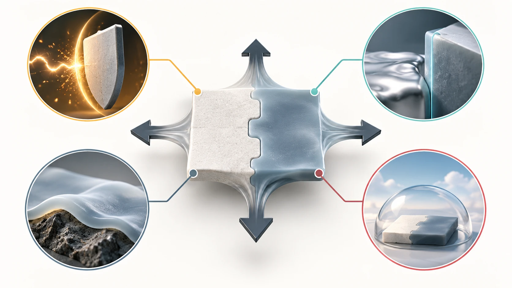
- Resist oxidation at a high-voltage cathode
- Resist reduction at the lithium-metal side
- Stay compliant and maintain contact at low pressure
- Remain practical to handle in air
| Requirement | Families said to answer it | As the published material puts it |
|---|---|---|
| 1 Withstand a high-voltage cathode | Halides (chlorides) | With a chloride solid electrolyte, fast charge and discharge is possible with no coating layer; LiCoO2 cycled stably to 4.22 V in experiment |
| 2 Withstand the low-potential side | Sulfides and garnet oxides | A sulfide solid electrolyte (Li6PS5Cl) was used on the anode side to avoid decomposition at low potential; the garnet type showed properties stable even in contact with Li metal |
| 3 Soft enough to adhere | Sulfides and soft-solid types | Sulfides are high in plasticity and easy to form; a solid electrolyte that also has flexibility makes interfacial joining to the electrode possible without applied pressure |
| 4 Handleable in air | Oxides and aqueous quasi-solid | Oxides are non-flammable and generate no toxic gas even in air; with the aqueous quasi-solid, every step of cell fabrication can now be carried out in air |
All Sourced (Hokkaido University [Source 1], Nagoya University [Source 7], Osaka Metropolitan University [Source 4], Sumitomo Chemical [Source 2], Institute of Science Tokyo [Source 3]). Sorting them into four requirements and mapping the families onto them is this article's own.
Read that table down a column and you find that no single family appears under both 1 and 2.
- The halides that answer 1 have an electrochemical window bottoming out at 1 V. They do not reach lithium metal (0 V)Sourced
- The oxides that answer 4 are low in plasticity, so they do not answer 3Sourced
- The sulfides that answer 3 react with moisture and release hydrogen sulfide, so they do not answer 4Sourced
Pick one and something always goes uncovered. That is not a failure of effort in materials search; it is that the requirements do not physically fit together. Withstanding high potential needs a framework from which electrons are hard to take (hard to oxidise); withstanding low potential needs one into which electrons are hard to push (hard to reduce). Those two are hard to ask of the same material at once (our commentary).
3. There are three ways to combine
The phrase "hybrid electrolyte" is in practice used for three different designs. Sorting the published examples, they divide as follows (our own grouping).
4. Route A: separate layers — different materials on the cathode and anode sides
The most straightforward route, and the example introduced in the Halide solid electrolyte article in this series belongs to it.
Using a cathode composite of the nickel-rich cathode (LiNi0.8Mn0.1Co0.1O2) and the solid electrolyte Li2ZrCl6 at 75:25, an all-solid-state battery in which a sulfide solid electrolyte (Li6PS5Cl) was used on the anode side to avoid decomposition at low potential was found to show a stable capacity of about 150 mAh g⁻¹ over 200 cycles at room temperatureSourced (Akira Miura and Kiyoharu Tadanaga, "Halide solid electrolytes", 2023)
5. Route B: insert a thin layer at the interface
Rather than setting two materials side by side as layers, a third material is placed thinly at the boundary alone. The examples from the Interfacial resistance article in this series apply directly.
| What is inserted | Thickness | Published effect | Source |
|---|---|---|---|
| Li3PO4 buffer layer | about 10 nm | Introduced at the Li3PS4 and LiCoO2 interface, cutting the internal resistance of the cell to 1/2,800 of its previous value | Tokyo Institute of Technology and the University of Tokyo (July 2022) |
| Thin Au layer | Not confirmed within the scope of this article | The Li and LLZO interfacial resistance fell from about 225 Ω cm² with ultrasonic bonding alone to about 1.5 Ω cm² | Tohoku University (March 2026) |
| Alloy layer | As left | A thin film of a metal that alloys with Li deposited on the LLZ surface. But after hundreds or thousands of plating and stripping cycles it disappears from the interface into the bulk Li, so it cannot be an essential solution | Nagoya University review (2020) |
All Sourced (Tokyo Institute of Technology [Source 5], Tohoku University [Source 8], Nagoya University review [Source 7]).
Route A (separate layers) solves a problem of potential. Different materials survive at the high and low ends, so you separate them.
Route B (insert at the interface) solves a problem of chemical reaction. Two materials react on contact, so you put something unreactive between them.
The thicknesses are orders apart. Route A's layers are tens of micrometres; route B's layer is 10 nmSourced. A difference of about a thousandfoldOur calculation (assumption: taking route A's layer as 10 µm, 10 µm divided by 10 nm = 1,000).
That difference becomes a difference in manufacturing technology. Layers tens of micrometres thick can be made by sheet forming or roll coating, but putting a 10 nm layer evenly on every individual powder particle is another technology entirely. The establishment in 2025 of an evaluation technology for coating thickness, mentioned in the Interfacial resistance article, connects here (our commentary).
6. Route C: mix the materials themselves — the soft-solid idea

The third route neither separates into layers nor inserts between them: it makes the material itself a composite. The soft-solid cell announced in November 2022 by Kyoto University, Tottori University and Sumitomo Chemical shows the idea most clearlySourced.
On the previous difficulty, it says solid electrolytes are hard and lack flexibility, so how to join the interface between solid electrolyte and electrode for good cell operation was the problem, and that the company developed a soft-solid cell in which a solid electrolyte that also has flexibility makes interfacial joining to the electrode possible without applied pressureSourced.
As the result, it states that a new flexible material made it possible to operate a high-capacity solid-state cell stably without applying pressure, obtaining about 230 Wh/kg in a pressure-free configurationSourced (Sumitomo Chemical, 7 November 2022)
As the Dendrite and Lithium metal anode articles in this series show, all-solid-state cells are built on the premise of being clamped from outside, to close voids and maintain contact.
That clamping mechanism is a component that generates no electricity. It costs mass, volume and money, and contributes nothing whatever to capacity.
Sumitomo Chemical states that omitting the pressure parts makes a substantial reduction in the weight and cost of the battery possibleSourced.
Make the material softer and a line disappears from the bill of materials. That goes a step beyond the point in the Sulfide solid electrolyte article that softness decides manufacturability. Softness changes not only ease of processing but the structure of the cell itself (our commentary).
One caution: the specific composition of the new flexible material, and how its flexibility arises, could not be confirmed in the news release this article consulted and are not stated here. The same applies to the configuration of the cell that gave about 230 Wh/kg (cathode, anode, areal capacity and so on).
7. Our calculation: the gains and losses of combining
Combining always has a price. More materials means more boundaries. It is worth checking the order of magnitude of that loss.
(1) What one extra dissimilar-material interface costsOur calculation
- Assumption: take the area resistance of the new interface as 10 Ω cm²
- Assumption: take the areal capacity as 3 mAh/cm², so 1C = 3 mA/cm² = 0.003 A/cm²
- ΔV = 0.003 × 10 = 0.03 V (about 0.8% of a 3.7 V cell voltage)
(2) How much resistance is the quasi-solid electrolyte layer itselfOur calculation
- Assumption: ionic conductivity 1 mS/cm (the lower bound of Institute of Science Tokyo's "above 1 mS/cm") and a layer 20 µm thick
- 2×10⁻³ cm divided by 1×10⁻³ S/cm = about 2 Ω cm²
(3) What you gain by removing the clampingOur calculation
- Assumption: suppose the clamping accounts for 10% of pack mass
- 1 divided by 0.9 = 1.11, so gravimetric energy density rises by about 11%
Assumptions and limits: the 10 Ω cm² in (1) and the 10% in (3) are both our own assumptions, not published values. Real dissimilar-interface resistance varies widely with the pair of materials and how they are made (the Interfacial resistance article reports a spread of 1.5 to 225 Ω cm²). These estimates exist to put gains and losses on the same footing, not to evaluate any particular design.
8. A materials engineer's view (1): not adding performance but dividing requirements
Anyone who works with composites will recognise the shape of this.
Fibre-reinforced plastic gives strength to the fibre and formability and integration to the resin. Neither is asked to do both. A hybrid electrolyte does the same: divide the requirements and assign a dedicated material to each.
And the problems composites always carry appear in the same way.
- More interfaces: just as the fibre and resin interface is the weak point, the interface between dissimilar electrolytes becomes resistanceOur calculation
- Mismatched expansion: when volume changes on cycling, two materials do not move alike
- More process steps: two materials have to be made separately and stacked in the right order
The Sulfide solid electrolyte article described this as the same shape as the thermal expansion discussion. Can you follow a partner whose dimensions move, without storing up stress? Combining takes that problem from one interface to two (our commentary).
Which is why the arithmetic of Section 7 matters. Does the gain from dividing exceed the loss from the added interface? That is the axis on which the decision to combine turns.
9. Outside the three routes: the aqueous quasi-solid path
All three routes so far sit inside the frame of how to combine inorganic solid electrolytes. The result Institute of Science Tokyo announced in August 2025 sits outside itSourced.
What was developed is an aqueous composite quasi-solid electrolyte composed of amorphous Li2B4O7-LiFSI-H2O, which shows an ionic conductivity above 1 mS/cmSourced. LiCoO2 is used as the cathode active material and Li4Ti5O12 as the anode active materialSourced.
The greatest significance lies in the process: every step of cell fabrication can now be carried out in airSourced. Aqueous systems bring their own constraint, though: previously, with water present, electrolysis of the water made it difficult to design cell voltages above 2 V on the lithium scaleSourced (Institute of Science Tokyo, 5 August 2025; published in Advanced Materials)
What makes this result interesting is the choice of where to put the constraint.
- Sulfides: voltage can be designed freely, but the manufacturing environment is constrained (an inert atmosphere is essential)Sourced
- Aqueous quasi-solid: the manufacturing environment is free, but voltage is constrained (electrolysis of water)Sourced
Take one and you lose the other. But what you lose differs in kind. A constraint on the manufacturing environment shows up as capital and running cost; a constraint on voltage shows up as energy density.
Which you accept depends on the application. For an EV, energy density dominates; for stationary or IoT use, manufacturing cost may dominate. As the Argyrodite article in this series shows, the first market for all-solid-state batteries is starting from small, high-reliability applications (our commentary).
10. A materials engineer's view (2): the trade-off polymers carry
Using an organic material in route C brings one unavoidable problem. A result announced in July 2024 by Tokyo University of Agriculture and Technology addresses it head onSourced.
There was a trade-off in which the changes in polymer structure and the addition of plasticiser needed to raise ionic conductivity cost strengthSourced (Tokyo University of Agriculture and Technology, 31 July 2024; published in Journal of Materials Chemistry A)
| Item | As published |
|---|---|
| Material | A mixture of a carbon dioxide and epoxide copolymer with a lithium salt, specifically poly(ethylene carbonate / ethylene oxide / allyl glycidyl ether) |
| Crosslinking sites | A comparatively high proportion of AGE units, about 30% |
| Cycling | More than 400 charge-discharge cycles |
| Researchers | Professor Yoichi Tominaga, Assistant Professor Kento Kimura and Nantapat Soontornnon (Tokyo University of Agriculture and Technology) |
| Publication | Journal of Materials Chemistry A (published online 25 June 2024) |
All Sourced (Tokyo University of Agriculture and Technology [Source 6]). Specific values for ionic conductivity and mechanical strength could not be confirmed on the page this article consulted and are not stated.
Make it easier to move and it gets softer. Anyone who has worked with polymers will feel the relationship intuitively.
For lithium ions to move through a polymer, the chains need freedom to move. So you add plasticiser, or lower the crystallinity. And the same operations take away strength as a material.
The Tokyo University of Agriculture and Technology result tries to solve this by crosslinking. Putting in AGE units at the high proportion of about 30% to increase crosslink points — keeping local chain motion while tying the whole into a networkSourced.
What a materials engineer should notice here is that the feedstock is carbon dioxideSourced. The Sulfide solid electrolyte article noted that the feedstock for Idemitsu Kosan's solid electrolyte was sulfur, a by-product of oil refining.
Both sulfur and carbon dioxide started life as things to be disposed of. An outlet in battery materials turned them into feedstock. Competitiveness in materials often emerges from the by-product side of another industry — a shape that keeps recurring in this field (our commentary).
11. What is still hard
(1) The composition of the soft solid is not published
Sumitomo Chemical's announcement speaks of a solid electrolyte that also has flexibilitySourced, but its specific composition, the combination of inorganic and organic constituents, and the mechanism giving the flexibility could not be confirmed in the news release this article consulted and are not stated here. The same applies to the configuration of the cell that reached about 230 Wh/kg (cathode material, anode material, areal capacity and so on).
(2) Dissimilar-interface resistance is not published as a number
For the interfacial resistance between dissimilar electrolytes arising in routes A and C, no specific value could be found in published primary sources within the scope of this article, so Section 7 uses an assumed value (10 Ω cm²).
(3) No production record can be confirmed
At the time of writing (September 2026), no primary source confirming that volume production of all-solid-state batteries using hybrid or composite electrolytes has begun could be foundNot yet confirmed.
(4) "Hybrid electrolyte" has no settled definition
This article sorts the field into three routes, but that is our own grouping and not a settled industry classification. Different papers and articles use "composite electrolyte", "hybrid electrolyte" and "quasi-solid electrolyte" for different scopes.
- No example of one material family meeting all four requirements was found within the scope of this article
- The ways of combining sort into three: separate layers, insert at the interface, mix (our own grouping)
- Route A solves a problem of potential; route B a problem of chemical reaction. Their thicknesses differ by about a thousandfoldOur calculation
- Add flexibility and the clamping component disappears. About 230 Wh/kg is reported without applied pressureSourced
- The gain from combining is pointless unless it exceeds the loss from the added interface (our commentary)
- The aqueous quasi-solid allows every step to be done in air, at the cost of a constraint on voltage designSourced
- Polymer systems carry a conductivity-versus-strength trade-off. Solving it by crosslinking has been reportedSourced
12. Glossary
- Hybrid electrolyte
- A design using several electrolyte materials of differing character together. There is no settled definition.
- Composite electrolyte
- An electrolyte blending two or more materials, often inorganic with organic.
- Quasi-solid electrolyte
- Not fully solid: it contains a liquid component but does not flow.
- Buffer layer
- A thin layer inserted at an interface to prevent reaction. About 10 nm is enough to work.
- Clamping mechanism
- Parts that press the cell from outside to maintain contact. They contribute nothing to capacity.
- Soft solid
- A solid electrolyte given flexibility, said to join to the electrode without applied pressure.
- Electrochemical window
- The range of potential over which an electrolyte does not decompose, with an upper and lower bound per material.
- Plasticiser
- An additive that softens a polymer. It makes ions more mobile and lowers strength.
- Crosslinking
- Tying polymer chains together into a network. It raises strength.
- Area-specific resistance (Ω cm²)
- Resistance per unit area, the unit used for interfaces and thin layers.
- Inert atmosphere
- An environment from which moisture and oxygen are excluded. Regarded as essential for sulfide processing.
- Gravimetric energy density
- Energy stored per kilogram of battery, in Wh/kg.
13. Primary sources
- Akira Miura and Kiyoharu Tadanaga (Faculty of Engineering, Hokkaido University) "Part 3, Chapter 1, Section 3: Halide solid electrolytes", in "Development of post-lithium-ion secondary batteries", 25 July 2023 (HUSCAP, PDF, Japanese-language page) — eprints.lib.hokudai.ac.jp
- Sumitomo Chemical "Successful joint development of a soft-solid cell: contributing to early practical use of next-generation batteries through higher capacity with a new material", 7 November 2022 (Japanese-language release) — sumitomo-chem.co.jp
- Institute of Science Tokyo "A world first: a new lithium-ion battery electrolyte made in air", 5 August 2025 (Japanese-language release) — isct.ac.jp
- H. Tsukasaki (Osaka Metropolitan University) "Elucidating the degradation mechanism of sulfide solid electrolytes in ambient atmosphere", Murata Science Foundation research report, 25 March 2024 (PDF, Japanese-language page) — corporate.murata.com
- Tokyo Institute of Technology "Origin of interfacial resistance in all-solid-state lithium batteries identified, with interfacial resistance cut to 1/2,800", July 2022 (Japanese-language page) — titech.ac.jp
- Tokyo University of Agriculture and Technology "A solid polymer electrolyte material for lithium secondary batteries combining ionic conductivity and strength, made from carbon dioxide", 31 July 2024 — tuat.ac.jp
- Soshu Motoyama, Takayuki Yamamoto and Yasutoshi Iriyama (Nagoya University) "Elucidating the short-circuit mechanism of solid electrolytes towards higher performance in all-solid-state Li batteries", Oyo Buturi vol. 89 no. 4 (2020) 213-217 (PDF, Japanese-language page) — jstage.jst.go.jp
- Tohoku University "Interface between lithium metal and a garnet-type oxide solid electrolyte formed at room temperature in a short time", 24 March 2026 (Japanese-language release) — tohoku.ac.jp
14. Claim-to-source audit
| Claim in the text | Basis | Label |
|---|---|---|
| That with a chloride solid electrolyte fast charge and discharge is possible with no coating layer; that LiCoO2 cycled stably to 4.22 V in experiment; that the lower bound of the chloride window is roughly 1 V; and that an all-solid-state battery using a cathode composite of LiNi0.8Mn0.1Co0.1O2 with Li2ZrCl6 at 75:25, with a sulfide (Li6PS5Cl) on the anode side to avoid low-potential decomposition, showed a stable capacity of about 150 mAh g⁻¹ over 200 cycles at room temperature | Akira Miura and Kiyoharu Tadanaga, "Halide solid electrolytes", 25 July 2023[Source 1] https://eprints.lib.hokudai.ac.jp/dspace/bitstream/2115/90346/1/20230725_3-1-3.pdf | Sourced |
| That conventional solid electrolytes are hard and lack flexibility so joining the interface to the electrode was the problem; that a soft-solid cell was developed in which a flexible solid electrolyte makes interfacial joining possible without applied pressure; that a new flexible material allowed stable operation of a high-capacity solid-state cell without pressure, giving about 230 Wh/kg in a pressure-free configuration; that omitting the pressure parts makes a substantial reduction in battery weight and cost possible; that the joint development partners are Kyoto University, Tottori University and Sumitomo Chemical; and that the announcement is dated 7 November 2022 | Sumitomo Chemical news release, 7 November 2022[Source 2] https://www.sumitomo-chem.co.jp/news/detail/20221107.html | Sourced |
| That the aqueous composite quasi-solid electrolyte is composed of amorphous Li2B4O7-LiFSI-H2O; that it shows an ionic conductivity above 1 mS/cm; that the cathode active material is LiCoO2 and the anode active material Li4Ti5O12; that every step of cell fabrication can now be carried out in air; that with water present, electrolysis previously made cell voltages above 2 V on the lithium scale difficult to design; and the announcement date of 5 August 2025, the researchers, and publication in Advanced Materials | Institute of Science Tokyo news, 5 August 2025[Source 3] https://www.isct.ac.jp/ja/news/ibduipkfrzhv | Sourced |
| That sulfide solid electrolytes exposed to the atmosphere react with moisture to generate toxic hydrogen sulfide (H2S); that an inert moisture-free atmosphere is essential for fabricating sulfide-type all-solid-state batteries and raises process cost; and that sulfides are high in plasticity and easy to form while oxides are chemically stable in air but low in plasticity | Murata Science Foundation research report, 25 March 2024[Source 4] https://corporate.murata.com/-/media/corporate/group/zaidan/report/study/202406/2024-002.ashx?la=ja-jp&cvid=20240802012731000000 | Sourced |
| That introducing a Li3PO4 solid electrolyte of about 10 nm as a buffer layer at the Li3PS4 and LiCoO2 interface cut the internal resistance of the cell to 1/2,800 of its previous value | Tokyo Institute of Technology news, July 2022[Source 5] https://www.titech.ac.jp/news/2022/064488 | Sourced |
| That the solid polymer electrolyte is a mixture of a carbon dioxide and epoxide copolymer with a lithium salt, specifically poly(ethylene carbonate / ethylene oxide / allyl glycidyl ether); that the crosslinking AGE units are at the comparatively high proportion of about 30%; that more than 400 charge-discharge cycles are possible; that the previous trade-off was that the polymer structural changes and plasticiser addition needed to raise ionic conductivity cost strength; and the researchers, publication in Journal of Materials Chemistry A (online 25 June 2024) and the announcement date of 31 July 2024 | Tokyo University of Agriculture and Technology press release, 31 July 2024[Source 6] https://www.tuat.ac.jp/english/outline/disclosure/pressrelease/2024/20240731_02.html | Sourced |
| That oxide solid electrolytes are non-flammable and generate no toxic gas even in air; that the garnet type showed properties stable even in contact with Li metal; and that depositing a thin film of a metal that alloys with Li on the LLZ surface cannot be an essential solution because after hundreds or thousands of plating and stripping cycles it disappears from the interface into the bulk Li | Review in Oyo Buturi vol. 89 no. 4 (2020) 213-217[Source 7] https://www.jstage.jst.go.jp/article/oubutsu/89/4/89_213/_pdf | Sourced |
| That the Li and LLZO interfacial resistance was about 225 Ω cm² with ultrasonic bonding alone and about 1.5 Ω cm² with a thin Au layer as well | Tohoku University press release, 24 March 2026[Source 8] https://www.tohoku.ac.jp/japanese/2026/03/press20260324-02-Lithium.html | Sourced |
| Putting the voltage drop at 1C from an added 10 Ω cm² interface at 0.03 V (about 0.8% of a 3.7 V cell); putting the area resistance of a 1 mS/cm quasi-solid in a 20 µm layer at about 2 Ω cm²; putting the gain in gravimetric energy density from removing the clamping at about 11%; and putting the thickness difference between route A and route B layers at about a thousandfold | Our calculation. The interface area resistance of 10 Ω cm², the areal capacity of 3 mAh/cm², the cell voltage of 3.7 V, the electrolyte layer thickness of 20 µm, the route A layer thickness of 10 µm and the clamping at 10% of pack mass are all assumptions set by this article and are not published values. The ionic conductivity of 1 mS/cm uses the lower bound of Institute of Science Tokyo's "above 1 mS/cm". This does not evaluate any particular design | Our calculation |
| The specific composition of the new material used in the soft-solid cell, the combination of inorganic and organic constituents, the mechanism of its flexibility, and the configuration of the cell that reached about 230 Wh/kg | Not stated in the news release this article consulted, so not given | Commentary |
| Measured values of the interfacial resistance between dissimilar electrolytes | Not found in published primary sources within the scope of this article, so Section 7 uses an assumed value (10 Ω cm²) | Commentary |
| Specific values for the ionic conductivity and mechanical strength of the Tokyo University of Agriculture and Technology polymer electrolyte | Not stated on the page this article consulted, so not given | Commentary |
| The thickness of the Au layer and the alloy layer | Could not be confirmed within the scope of this article, so the table records them as not confirmed | Commentary |
| The start of volume production of all-solid-state batteries using hybrid or composite electrolytes | No primary source indicating the start of volume production could be confirmed at the time of writing (September 2026) by this article | Not yet confirmed |
| Sorting the field into four requirements and mapping families onto them; grouping the ways of combining into A (separate layers), B (insert at the interface) and C (mix); the reading that A solves a problem of potential and B a problem of chemical reaction; the framing that combining is division of requirements rather than addition of performance; the analogy with fibre-reinforced plastic; the framing of where the constraint sits, manufacturing environment or voltage; and the reading that sulfur and carbon dioxide both went from things to be disposed of to feedstock | Our summary and commentary based on published content. Not views expressed by the institutions or companies. There is no settled industry definition or classification of hybrid electrolytes | Commentary |
| That Figs. 1, 2, 3, 5, 6 and 7 are explanatory drawings rather than real observations or design drawings, and that the hero image and Fig. 4 are AI-generated images | Our note | Commentary |
Last updated 21 September 2026. Sources are limited to primary material (official university announcements and reviews in academic repositories, company news releases, and research reports funded by public grants). Because the article includes structural readings and materials-design interpretations, those are marked as Commentary and kept separate from sourced fact. The composition of the soft solid, measured dissimilar-interface resistances, the conductivity and strength of the polymer electrolyte, and any production record are not stated here because no published primary source could be confirmed. Every calculation in Section 7 is an estimate resting on assumptions set by this article and does not evaluate any particular design. The three-route classification is also our own and is not a settled industry classification. All figures are explanatory concept graphics. Figs. 1, 2, 3, 5, 6 and 7 are vector drawings; the hero image and Fig. 4 are AI-generated images, and none of them shows a real cross-section, micrograph or physical product.