TECHNOLOGY EXPLAINER
Orbital computing
— Processing data in space: what has been shown, and what is still a concept
Small demonstrations of AI and data processing on satellites are already under way. The idea of building data centers in space, however, is still mostly at the plan or research stage. This article is written so that a materials engineer with no background in spaceflight can follow it. It explains (1) why anyone wants to compute in space, (2) what has been demonstrated and what is still a concept, and (3) the four constraints — power, heat, radiation and communication — with worked numbers. It does not claim that commercial operation has begun. Company statements are treated as company statements, and no company is ranked above another.
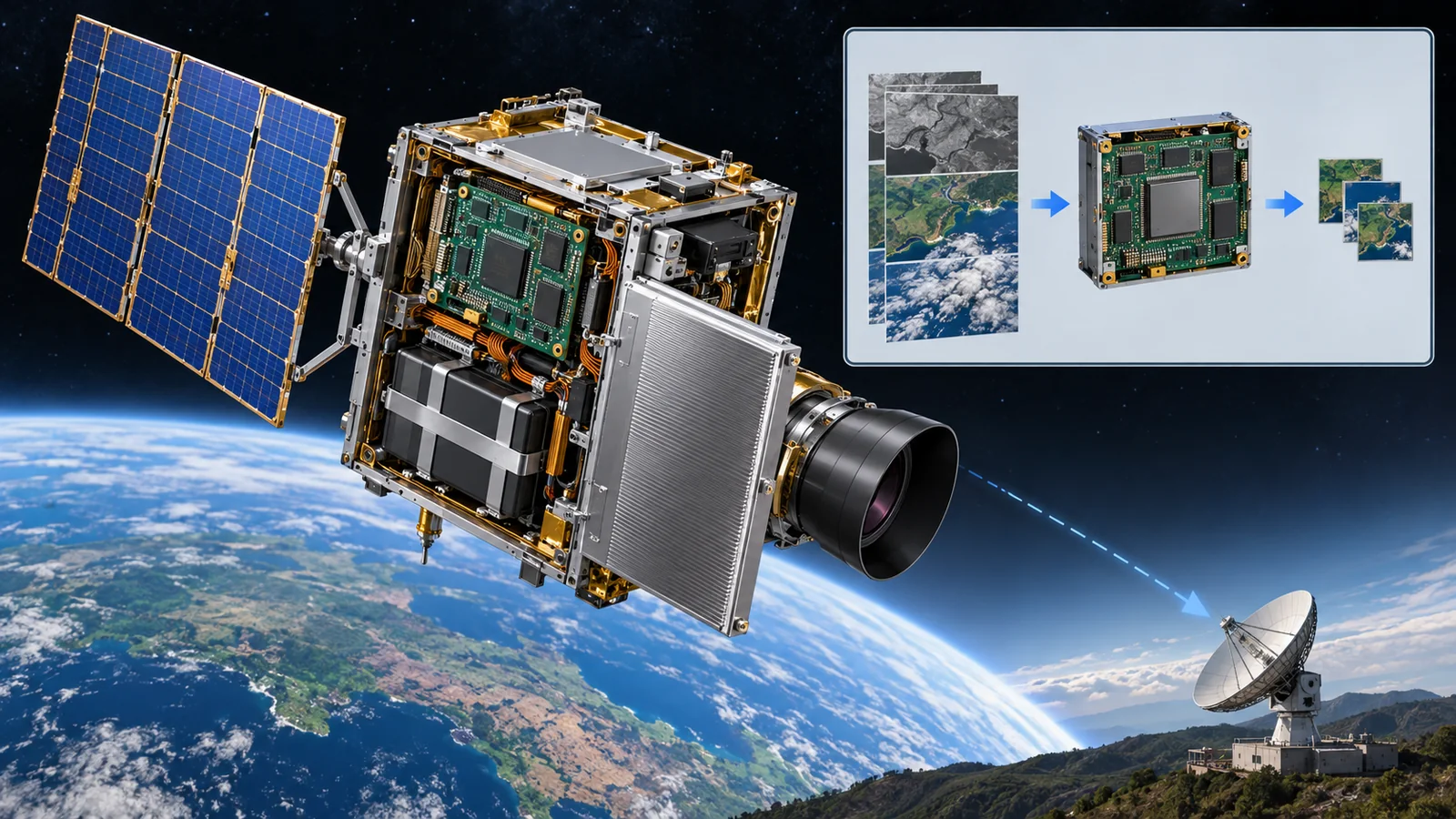
- The short version / what to know first / place in the series
- Why compute in space? Two motives
- What is demonstrated and what is a concept: four stages
- Constraint 1: power, with a 1 MW example
- Constraint 2: heat, which can leave only by radiation
- Constraint 3: radiation, and commercial AI chips
- Constraint 4: communication, a limited data pipe
- Inside the concepts: Suncatcher, Starcloud, ASCEND and a filing
- A materials engineer's view
- Yardsticks and standards / glossary / references / audit
Sourced = stated in a published source (link given)
Our calculation = a value this article calculated from stated assumptions
Not yet confirmed = company targets and plans, pending applications and studies — anything not settled
Inference is shown in bold. Every analogy comes with its limits.
The area, power and dose numbers in Chapters 4-6 are explanatory values calculated here, not design values of any real satellite. Company performance and plans are reported as company statements, and no company is ranked. Each in-orbit demonstration is described by what, how large and when. This field moves fast, so the status of every example carries a check date (17 October 2026).
1. The short version, what to know first, and where this fits
- Two reasons: to shrink data on the satellite that cannot all be sent to the ground (demonstrated), and to use space sunlight for large-scale computing (still a concept) Sourced [ref. 2, 13, 7]
- What has been shown is small: one AI chip, a few servers, two prototype nodes. I could not find a primary source showing a data-center-scale operation Sourced [ref. 4, 7, 14]
- Four walls: power, heat, radiation and communication. In a vacuum heat leaves only by radiation, so radiator area sets how much computing is possible Our calculation [ref. 16, 6]
No background in spaceflight is needed. Think of an orbit as falling continuously while moving sideways fast enough never to hit the ground (the cannonball analogy; its limit: thin air and uneven gravity change real orbits slowly). Low Earth orbit (LEO) means altitudes from a few hundred to about 2,000 km, where a satellite circles the Earth in about 90 minutes (our calculation: ~95 minutes at 500 km) Our calculation. We also use the fact that nearly all the electric power a computer uses ends up as heat.
The space environment (the "five enemies": vacuum, radiation, temperature swings and so on) is covered in our explainer on the space environment, radiation in the one on radiation and electronics, and space-grade chips in the one on space semiconductors and COTS. For the basics of AI on devices, read our explainer on edge AI and on-device AI first. The next articles, on low-Earth-orbit constellations and inter-satellite optical links, continue with the light-link side.
2. Why compute in space? Two motives
Start with an everyday case. A camera on a mountain top takes a huge number of photos each day, but only a thin phone line runs down to town. Sending every photo would take days. Put a small computer next to the camera, let it discard cloudy photos and send only places where something changed, and the thin line is enough. Satellites are in the same position.
Motive 1: shrink the data before sending it down (AI on the satellite)
An observation satellite produces a great deal of data with its cameras and radar. It can send data down only in short windows, for example a few minutes while passing over a ground station. So it processes the data first: it discards unusable images and extracts only what is needed. Axiom Space's chief executive has said that the answer is not simply more bandwidth but less dependence on bandwidth (a company statement) Sourced [ref. 7]. This is the starting point for most uses of AI in space.
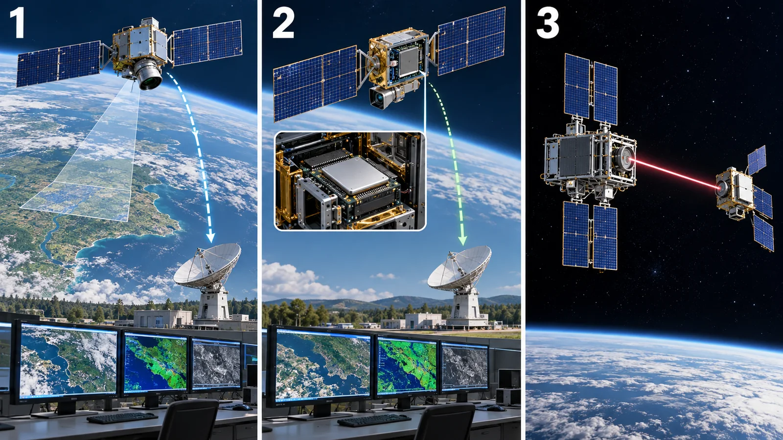
View original SVG, values and sources
Original SVG reference: Conceptual diagram (vector drawing). A and B are forms that have been demonstrated; C is a concept. Arrow thickness suggests the rough difference in data volume.
As a concrete case, HPE reports that sending 1.8 GB of raw DNA-sequence data from the International Space Station (ISS) to the ground had averaged 12.2 hours, whereas processing it aboard in six minutes, compressing it to 92 KB and sending it took about two seconds. This is a company statement; I did not confirm the details of the conditions, such as link state Sourced [ref. 13].
Motive 2: use space sunlight for large-scale computing (concept)
The other motive comes from the power and cooling burden of ground data centers. A Google research team writes that in a suitable orbit a solar panel can be up to 8 times more productive than on Earth and can produce power almost continuously Sourced [ref. 2]. That is a research-stage estimate. Google itself says that thermal management, high-bandwidth ground communication and on-orbit reliability remain significant engineering challenges Sourced [ref. 2]. Motive 2 sits at the "concept" stage in Chapter 3.
The background of space is cold, about 2.7 K (about -270 °C), but with no air to carry heat, heat can leave only as infrared radiation. A vacuum flask keeps tea hot for the same reason: a vacuum makes heat hard to shed. To dump a computer's heat into space you need a large radiating panel (Chapter 5). Limit of the analogy: a flask is built to trap heat, while in space the aim is the opposite — a wide surface that radiates it away.
3. What is demonstrated and what is a concept: four stages
The phrase "data center in space" is sometimes used for things of completely different scale. So we sort them by maturity. ISO 16290 defines technology readiness levels (TRLs) for space systems, grading technology from concept to flight record Sourced [ref. 23]. Using it as a guide, we use four simple stages.
| Example | What, how large, when | Type |
|---|---|---|
| Phi-Sat-1 (ESA) | Carried on the FSSCat CubeSat. An AI chip (Intel Movidius Myriad 2) on board judged hyperspectral images and discarded cloudy ones. ESA announced the launch on a Vega rocket for September 2020. Reported figures: 92% accuracy, 1% false positives, about 2 W and 325 ms per inference (as recapped by a later paper). What ran on board was inference (running a trained model) Sourced [ref. 10, 11, 12] | Sourced |
| HPE Spaceborne Computer-2 | Commercial servers (Edgeline and ProLiant) installed on the ISS. Launched in February 2021 and installed in May 2021; HPE reported 24 completed experiments by April 2022. The sources checked do not say exactly where on the station they sit Sourced [ref. 13] | Sourced |
| BUPT-1 (12U satellite) | Sun-synchronous orbit at ~490 km. Two Raspberry Pi 4B boards and two Atlas 200 DK accelerators flew as commercial payloads; power, battery and temperature were logged for about four months. A preprint, not yet peer-reviewed Sourced [ref. 14] | Sourced |
| Starcloud-1 | One NVIDIA H100 on a satellite of about 60 kg (per NVIDIA's pre-launch article). Launched in November 2025. The company says it trained a small language model (nanoGPT) and ran a Google language model in orbit (a company claim; no third-party verification found) Sourced [ref. 3, 4] | Sourced |
| Axiom ARC-1 and ARC-2 | Two compute nodes riding on Kepler's optical-relay satellites, launched in 2026. Node-to-node and node-to-ground communication was confirmed; the company calls it prototype infrastructure. An in-orbit post-quantum-cryptography demonstration is the next goal Sourced [ref. 7] | Sourced |
| Project Suncatcher (Google) | At the paper and bench-test stage. Two prototype satellites with Planet are planned by early 2027 Not yet confirmed [ref. 2, 1] | Not yet confirmed |
| Starcloud-2 | The company states it will be fully operational in sun-synchronous orbit by 2027 (company plan) Not yet confirmed [ref. 5] | Not yet confirmed |
| SpaceX "Orbital Data Center" application | Up to one million satellites at 500-2,000 km. The FCC accepted it for filing and sought comment on 4 February 2026. This is acceptance of an application, not a grant; I could not confirm any later decision Not yet confirmed [ref. 8] | Not yet confirmed |
| ASCEND (Europe) | A feasibility study started in 2023, funded by the European Commission (Horizon Europe). Results were announced in June 2024; the aim stated is one gigawatt before 2050 (a company announcement) Not yet confirmed [ref. 9] | Not yet confirmed |
The arrangement of this table is Our calculation (organisation only). Company announcements are company statements; third-party verification was not found.
AI running on a satellite (Phi-Sat-1 and others) has been demonstrated since 2020. A "data center", on the other hand, means a facility with many computers that are cooled, linked at high speed and replaced when they fail. A satellite with one H100 extends the first idea; it has not reached the scale of the second. Keeping this difference in mind makes headlines easier to read.
4. Constraint 1: power, with a 1 MW example
In space, power comes from solar cells. A surface facing the Sun in Earth orbit receives about 1,361 watts per square metre (total solar irradiance, reported as 1360.8 ± 0.5 W/m² from satellite measurements) Sourced [ref. 15]. A solar cell, though, turns only part of this into electricity — 22%, for example.
How much area does a 1-megawatt (1 MW = 1,000,000 W) computer need? When estimating satellite power, Google's paper assumes 22% cell efficiency and 90% packing [ref. 1]. We borrow the same assumptions.
Our calculation Electric output = 1,361 W/m² × 0.22 × 0.9 = about 269.5 W/m². 1,000,000 W ÷ 269.5 W/m² = about 3,711 m². For heat, Starcloud's white paper assumes a 20 °C (293.15 K) plate with emissivity 0.92 that radiates 770.5 W/m² from both faces, minus absorbed sunlight and Earth heat, leaving a net 633.1 W/m²; 1,000,000 ÷ 633.1 = about 1,580 m² (a calculation using the company's assumptions). An H100 draws up to 700 W, so 1 MW is about 1,430 chips counting the chips alone (no other server parts or networking). Sources: [ref. 15, 1, 6, 17]
For comparison, NASA lists the ISS as producing 75 to 90 kilowatts in total Sourced [ref. 18]. 1 MW is about 11 to 13 times that. Running 1 MW of computing in space therefore means launching and unfolding the electrical equivalent of more than ten space stations.
"Constant sunlight" depends on the orbit chosen. In the Earth's shadow a satellite runs on batteries. In our calculation, on a circular orbit at 500 km (about 95 minutes) the longest time in shadow is about 36 minutes Our calculation. Google's concept picks a "dawn-dusk" sun-synchronous orbit that rides the line between night and day, so sunlight is almost constant and batteries can be small Sourced [ref. 2]. The price is that communication delay grows for some ground locations Sourced [ref. 1].
Sunlight is strong and steady, but the cost of launching the area and mass of solar cells becomes the cost of the electricity. Google's paper estimates that costs could become comparable to terrestrial energy costs if launch prices fall to about US$200 per kilogram or less — an assumption for the mid-2030s, not today's price SourcedNot yet confirmed [ref. 1]. If the premise fails, the conclusion changes.
5. Constraint 2: heat, which can leave only by radiation
A ground data center carries its heat away with air or water. A vacuum has no carrier, so heat must leave a surface as infrared radiation. The heat a surface can emit grows with the fourth power of its temperature (the Stefan-Boltzmann law): P = emissivity × σ × T⁴, where T is absolute temperature in kelvin and σ is the constant 5.670 × 10⁻⁸ W/(m²·K⁴) Sourced [ref. 16]. Let us check with numbers.
At 20 °C (293.15 K) a face emits about 385 W/m²; at about 77 °C (350 K) about 780 W/m² Our calculation. Raising the temperature by 57 °C roughly doubles the heat shed. This is why spacecraft keep radiator temperature up with a heat-carrying fluid and gather heat with heat pipes. But chips and batteries have temperature limits, so the plate cannot simply be made hot. The "temperature staircase" from chip to plate is governed by the thermal resistance of materials (Chapter 9).
If absolute temperature doubles, the radiated heat rises 2⁴ = 16-fold (always use absolute temperature: 20 °C is 293 K and 77 °C is 350 K, so a 1.2-times higher temperature gives about twice the heat). If heat can be handed to the plate at a slightly higher temperature, the plate can be smaller. The wish to keep the chip cool pushes the other way and makes the plate bigger. This tug of war is the heart of thermal design.
What happens in a real orbit? The BUPT-1 report (a preprint) measured the thermal limit on a small satellite carrying commercial AI accelerators. One accelerator at full load took about nine hours to bring the satellite's structural surface to its 30 °C limit. Two accelerators on the same surface reached the limit in about 40 minutes; the operating system killed a task at about 50 minutes and the second device was powered down at about 110 minutes Sourced [ref. 14]. Sharing one radiating surface sharply shortens usable time.
The right-hand chart is about the battery. In shadow only the battery supplies power, and a deeper depth of discharge shortens its life. The same report found an average of about 16% in normal operation but about 35% during multi-day computing, beyond the 30% design limit Sourced [ref. 14]. Computing loads power, heat and battery life all at once.
6. Constraint 3: radiation, and commercial AI chips
Space is full of energetic particles — protons and cosmic rays — that the atmosphere and magnetic field would block on the ground. Semiconductors suffer mainly two effects. (1) Total ionizing dose (TID): charge slowly builds up in insulating layers under constant exposure, and performance degrades. (2) Single-event effects (SEE): one particle passing through flips a bit or upsets a circuit at that instant. They are studied by firing particles from a ground accelerator at the chip (see our explainer on radiation and electronics).
Google tested its AI chip Trillium (TPU v6e) and its host server with a 67 MeV proton beam, and describes the result as the first published radiation-test data for such a device (a company report) Sourced [ref. 1]. The main results:
- For a sun-synchronous orbit with shielding equal to about 10 mm of aluminium, the dose was estimated at about 150 rad(Si) per year, or about 750 rad(Si) over five years.
- Stress tests of the high-bandwidth memory (HBM) began to show irregularities at a cumulative 2 krad(Si). Other tests ran correctly up to the maximum tested, 15 krad(Si) on one chip, with no hard failure attributed to TID.
- In core logic and on-chip memory, "silent data corruption" — wrong results that go unnoticed — was observed at roughly one event per 17 rad.
Let us push one step further with our own calculation. If silent corruption occurs once per 17 rad and the chip receives 150 rad a year, that is 150 ÷ 17 = about 8.8 events a year. One inference per second for a year is about 31.5 million, so roughly one error per 3.6 million inferences. Google's paper gives a similar estimate of about one per 3 million Our calculation [ref. 1]. That may be acceptable for inference, but in training one error can spoil a result, and the paper itself says more study is needed.
Dose is given in rad or Gy; 1 Gy = 100 rad. "(Si)" means the amount absorbed in silicon. 750 rad(Si) is 7.5 Gy. The number depends strongly on shielding thickness, orbit altitude and duration. The values quoted are Google's estimate for a sun-synchronous orbit with about 10 mm of aluminium-equivalent shielding; they cannot be applied to other orbits, for example inside the radiation belts.
The BUPT-1 report states that at about 490 km and about four months, radiation was not the limit for its commercial boards; heat and power were Sourced [ref. 14]. Radiation matters more as missions get longer and chips more advanced.
7. Constraint 4: communication, a limited data pipe
A low-orbit satellite can talk to a given ground station only for a few minutes while it passes overhead. As HPE's example showed, limits on the time and speed of downlinks from the ISS created the value of processing on the spot Sourced [ref. 13]. There is also the delay set by the speed of light: about 1.7 milliseconds one way at 500 km, about 119 ms from geostationary orbit (about 35,786 km up) and about 1.3 seconds to the Moon (our calculation, distance divided by the speed of light) Our calculation.
Another challenge is communication between orbiting computers. AI training needs many chips to swap data very fast. Google estimates that ground-data-center-like performance needs tens of terabits per second between satellites, and proposes flying satellites within hundreds of metres so the received light is strong. On a bench it reports 800 Gbps each way (1.6 Tbps total) with one transceiver pair Sourced [ref. 2]. That was a ground test, not an in-orbit one (optical links get their own article).
bps means bits per second. 1 Gbps (giga) is a billion bits per second and 1 Tbps (tera) is 1,000 times that. 800 Gbps is about 100 gigabytes per second (dividing by 8 bits per byte; our calculation) Our calculation. That is hundreds of times a home fibre service, yet AI training with thousands of chips talking still needs "tens of terabits".
8. Inside the concepts: Suncatcher, Starcloud, ASCEND and a filing
Each concept aims to "compute in space", but their design ideas differ. Without ranking them, here are the differences as published.
- Project Suncatcher (Google): a "distributed" design of many small satellites flying close together and linked by light. The paper uses a 81-satellite swarm of 1 km radius at about 650 km, with neighbours about 100-200 m apart. The paper is a preprint and Google calls the work research Sourced [ref. 2, 1]
- Starcloud: a long-term concept of a large "monolithic" data center with huge solar arrays and radiators; its white paper gives a 4 km square, 5 GW example. It first flew one H100 on the small Starcloud-1. The concept's numbers are company estimates SourcedNot yet confirmed [ref. 6, 3, 4]
- ASCEND (Europe): a study comparing environmental impact and checking technical feasibility of in-orbit assembly. The announcement assumes cooling without water and a launcher with far lower emissions Not yet confirmed [ref. 9]
- SpaceX application: an "orbital data center" of up to one million satellites using mainly optical inter-satellite links. Whether it has been granted is unconfirmed Not yet confirmed [ref. 8]
The FCC notice (DA 26-113) shows only that the application was accepted for filing and comment was sought; it is not a grant. The filing itself asks for waivers of the usual deployment-milestone and surety-bond requirements Sourced [ref. 8]. Authorisation and actual launch are separate steps. Likewise "one gigawatt before 2050" in a study is a target, not a settled plan.
9. A materials engineer's view
Heat flows from the chip through the junction, a thermal interface material (TIM), a heat spreader, heat pipes or coolant channels and the radiator, and finally leaves as infrared. Google's paper also says that shedding the heat of an advanced TPU in vacuum requires "advanced thermal interface materials and, preferably, passive heat transport" Sourced [ref. 1]. Since air cooling is unavailable, each interface's thermal resistance and its degradation under thermal cycling (delamination, pump-out) set lifetime and scale directly. The materials in our explainers on spacecraft thermal control and on thermal-control materials and radiative cooling underpin the computer here.
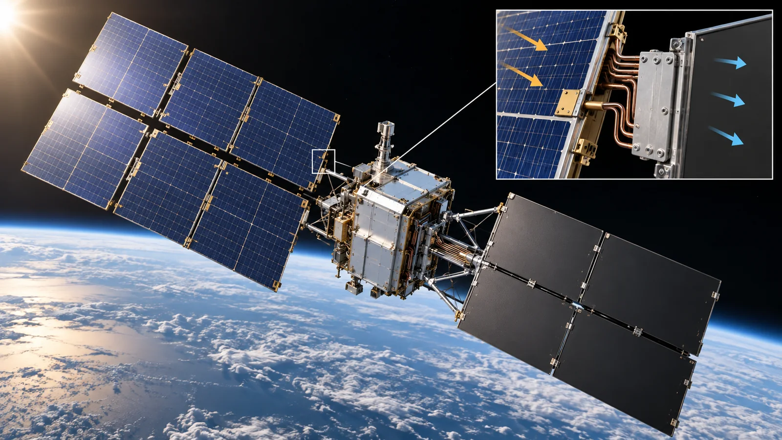
A radiator surface should emit infrared well (high emissivity) yet absorb little sunlight (low absorptance). Starcloud's white-paper calculation uses an emissivity of 0.92 and absorptance of 0.09, and absorbed sunlight and Earth heat reduce net heat shed by about 18% (770.5 to 633.1 W/m²) Our calculation [ref. 6]. In orbit, however, ultraviolet light, atomic oxygen and particles can raise a coating's or film's absorptance over time (degradation). The measurement of thermo-optical properties of thermal-control materials is set out in ECSS-Q-ST-70-09C Sourced [ref. 19]. When reading numbers for a multi-year life, always check whether they are initial or end-of-life values.
Using advanced AI chips in space follows the trend of bringing commercial off-the-shelf (COTS) parts into space. The European standard ECSS-Q-ST-60-13C Rev.2 (30 April 2025) sets rules for commercial EEE (electrical, electronic and electromechanical) parts on spacecraft Sourced [ref. 19]. Shielding adds mass; Starcloud's white paper argues that shielding mass per unit of compute falls as the container gets larger Sourced [ref. 6]. On the materials side, shielding (aluminium, tantalum and so on) and the radiation tolerance of boards, encapsulants and solder must be optimised together with mass, heat and cost. This article does not give figures for individual materials or thicknesses, because none could be confirmed.
Google's paper says that, since failed chips cannot be swapped by people in orbit, carrying spares (redundancy) is the simplest remedy, and that high-speed optical links to the ground and in-orbit repair are still to be solved Sourced [ref. 1]. From a materials viewpoint, interfaces, adhesives and coatings that do not degrade over several to ten years without maintenance look like the biggest hidden cost driver (Inference).
10. How to read the yardsticks and standards
No single number measures orbital computing. Read a combination of (1) how far it has been demonstrated (technology readiness), (2) how much radiation it survived (total-dose and single-event tests), (3) whether it worked in thermal vacuum, and (4) how much work it did on how much power. A standard way to compare compute performance in orbit, however, could not be found. Peak figures such as TOPS or GPU count do not reveal sustained performance.
| What is assessed | Typical test or method (name, source) | Standards and guidance | Reading notes |
|---|---|---|---|
| Maturity stage | Technology readiness levels grade technology from concept to flight record. The four stages here are a simplification (Our calculation) | ISO 16290:2013 "Space systems — Definition of the Technology Readiness Levels (TRLs) and their criteria of assessment" (confirmed in 2024) [ref. 23] Sourced | Scale differs within a stage. A one-chip demo is not a data-center demo |
| Total ionizing dose | Chips are irradiated in steps from a ground source or accelerator while electrical properties are measured. Google used 67 MeV protons Sourced | ESCC 22900 Issue 5 "Total Dose Steady-State Irradiation Test Method" [ref. 20] Sourced / ECSS-Q-ST-60-15C Rev.1 "Radiation hardness assurance" (20 March 2025) [ref. 19] Sourced | Dose depends on shielding, orbit and duration. Check conditions behind any bare "rad(Si)" figure |
| Single-event effects | Heavy ions or protons are fired at the chip to measure how readily upsets occur (cross-section) | ESCC 25100 Issue 2 "Single Event Effects Test Method and Guidelines" [ref. 20] Sourced / JEDEC JESD57A (heavy ions, November 2017) [ref. 21] Sourced / JEDEC JESD234 (protons 40-500 MeV, October 2013) [ref. 22] Sourced | In AI training, undetected errors are the issue. Look at detection as well as error rates |
| Use of commercial parts | Combine part-level test results with system-level error detection and redundancy | ECSS-Q-ST-60-13C Rev.2 "Commercial electrical, electronic and electromechanical (EEE) components" (30 April 2025) [ref. 19] Sourced | Text of the standard not checked. Title and issue date only |
| Thermal and thermal vacuum | Run the hardware in thermal vacuum and check that heat rejection matches the design. In orbit, record temperature and power as BUPT-1 did Sourced | ECSS-E-ST-31C "Thermal control" (15 November 2008) / ECSS-E-ST-10-03C Rev.1 "Testing" (31 May 2022) / ECSS-Q-ST-70-09C "Measurements of thermo-optical properties of thermal control materials" (31 July 2008) [ref. 19] Sourced | Ground thermal-vacuum tests differ from orbital behaviour; sun, Earth and shadow conditions matter |
| Space-environment definition | Environment models of radiation, temperature and so on for each orbit | ECSS-E-ST-10-04C Rev.1 "Space environment" (15 June 2020) [ref. 19] Sourced | A standard model is not the same as real space-weather variation |
| Compute performance and efficiency (in orbit) | Not found (no standard way to compare compute performance in orbit was found; BUPT-1 stresses sustained throughput under thermal and power limits Sourced) | Not found | Peak TOPS or GPU counts do not describe sustained performance |
| Plans and targets | — (plans, not assessments). Suncatcher prototypes (by early 2027), Starcloud-2 (by 2027), ASCEND (aim: 1 GW before 2050) Not yet confirmed | Not found (no standard) | Plans are not achievements. Delays and changes are common |
The arrangement of this table is Our calculation (organisation only). ECSS numbers, titles and dates come from the ECSS list, ESCC issues from the ESCC list, and JEDEC and ISO items from their official pages (checked 17 October 2026). The texts of the standards were not checked.
Reading notes for materials engineers
- Ground tests are not in-orbit records: Google's proton test is an accelerator result, not a long-term failure rate in orbit. BUPT-1's measurements cover a small satellite for about four months and do not guarantee data-center-scale thermal design.
- Company announcements are not third-party verification: Starcloud-1's training results, HPE's 20,000-fold speed-up and ASCEND's economics are all company statements. Independent reproduction was not found.
- Check whether a standard is advice or a requirement: ECSS standards apply to European space projects according to contract and procurement terms. JEDEC test standards define how to run tests. None certifies that hardware can serve as a data center in orbit.
- Plans are not achievements: targets for 2027 or 2050 are not settled facts.
11. Glossary
- Orbit
- Falling continuously while moving sideways fast enough not to hit the ground.
- Low Earth orbit (LEO)
- An orbit a few hundred to about 2,000 km up; one lap of Earth takes about 90 minutes.
- Geostationary orbit (GEO)
- About 35,786 km up; the satellite appears fixed in the sky.
- Sun-synchronous orbit
- An orbit whose plane keeps a fixed angle to the Sun. The dawn-dusk type rides the day-night line and sees almost constant sunlight.
- Orbital computing
- Processing data or running AI on satellites and spacecraft.
- Space data center
- A concept of placing many computers in orbit for large-scale processing. At present a concept and research stage.
- Edge processing
- Processing data close to where it is created.
- GPU / TPU
- Parallel-processing chips used for AI. The TPU is Google's AI chip.
- H100
- NVIDIA's data-center GPU; the SXM version draws up to 700 W.
- HBM (high-bandwidth memory)
- Fast memory stacked next to the chip.
- Total solar irradiance
- Sunlight per unit area on a surface facing the Sun in Earth orbit; about 1,361 W/m².
- Thermal radiation
- An object emitting heat as infrared. The only way heat leaves in a vacuum.
- Emissivity
- A 0-1 value of how readily a surface radiates heat.
- Absorptance
- A 0-1 value of how much sunlight a surface absorbs.
- Stefan-Boltzmann law
- Radiated heat is proportional to the fourth power of absolute temperature.
- Heat pipe
- A sealed tube that moves heat by evaporating and condensing an internal fluid.
- Thermal interface material (TIM)
- A material that fills the gap between two surfaces so heat flows more easily.
- Depth of discharge (DoD)
- The fraction of a battery's capacity that has been used.
- Total ionizing dose (TID)
- The accumulated amount of radiation received; unit rad or Gy.
- Single-event effect (SEE)
- A fault caused by one particle, such as a bit flip.
- Silent data corruption (SDC)
- Wrong results that are produced without anyone noticing.
- COTS (commercial off-the-shelf)
- Commercial parts or equipment not designed specially for space.
- Technology readiness level (TRL)
- A scale grading how far a technology has progressed from concept to operation.
- Optical link
- Communication by laser light.
- ISS (International Space Station)
- A crewed facility in low orbit.
12. References
- Agüera y Arcas B. et al. (Google) "Towards a future space-based, highly scalable AI infrastructure system design", arXiv:2511.19468 v2 (revised 17 June 2026; preprint) — arxiv.org/abs/2511.19468
- Beals T. (Google Research) "Exploring a space-based, scalable AI infrastructure system design" (introduction to Project Suncatcher, 4 November 2025) — research.google/blog
- Lee A. (NVIDIA) "How Starcloud Is Bringing Data Centers to Outer Space" (pre-launch feature, 15 October 2025) — blogs.nvidia.com/blog/starcloud
- Starcloud, Inc. "Starcloud-1" page (company page; checked 17 October 2026) — starcloud.com/starcloud-1
- Starcloud, Inc. "Starcloud-2" page (company page; checked 17 October 2026) — starcloud.com/starcloud-2
- Feilden E., Oltean A., Johnston P. (Lumen Orbit, now Starcloud) "Why we should train AI in space", White Paper v1.03 (September 2024; company concept paper) — starcloud.com/wp
- Axiom Space "Axiom Space, Kepler Ready Orbital Computing for Quantum Era" (press release, 6 October 2026) — axiomspace.com/release/axiom-space-kepler-ready-orbital-computing-for-quantum-era
- FCC Space Bureau DA 26-113 "Space Bureau Accepts for Filing SpaceX's Application for Orbital Data Centers" (public notice, 4 February 2026) — docs.fcc.gov/public/attachments/DA-26-113A1.pdf
- Thales Alenia Space "Thales Alenia Space reveals results of ASCEND feasibility study on space data centers" (press release, 27 June 2024) — thalesaleniaspace.com/en/press-releases/…ascend…
- Giuffrida G. et al. "The Φ-Sat-1 Mission: The First On-Board Deep Neural Network Demonstrator for Satellite Earth Observation", IEEE Trans. Geosci. Remote Sens. 60 (2022), DOI 10.1109/TGRS.2021.3125567 — doi.org/10.1109/TGRS.2021.3125567
- ESA "Vega V16 launch live with SSMS and ESAIL" (launch-coverage notice; states that FSSCat, which carries Φ-sat-1, is on board) — esa.int/…/Vega_V16_launch_live_with_SSMS_and_ESAIL
- Cratere A. et al. "Efficient FPGA-accelerated Convolutional Neural Networks for Cloud Detection on CubeSats", IEEE J. Miniaturization for Air and Space Systems (2025; recaps published CloudScout figures), DOI 10.1109/JMASS.2025.3533018; preprint — arxiv.org/abs/2504.03891
- Hewlett Packard Enterprise "Hewlett Packard Enterprise drives innovation at the extreme edge on the International Space Station with 24 completed experiments" (press release, 4 April 2022) — hpe.com/…/24-completed-experiments.html
- Li Q. et al. "AI Infrastructure in Space: How Far Can We Go?", arXiv:2608.21034 (21 August 2026; not yet peer-reviewed preprint) — arxiv.org/abs/2608.21034
- Kopp G., Lean J. L. "A new, lower value of total solar irradiance: Evidence and climate significance", Geophys. Res. Lett. 38, L01706 (2011) (NASA abstract page) — espo.nasa.gov/node/30086
- NIST CODATA 2022 "Stefan-Boltzmann constant" — physics.nist.gov/cgi-bin/cuu/Value?sigma
- NVIDIA "NVIDIA H100 Tensor Core GPU" (product page; maximum thermal design power: up to 700 W for the SXM version, configurable) — nvidia.com/en-us/data-center/h100
- NASA "Space Station Facts and Figures" (eight solar arrays provide 75 to 90 kW) — nasa.gov/…/space-station-facts-and-figures
- ECSS "List of published ECSS Standards (long)" (numbers, titles and issue dates; checked 17 October 2026) — ecss.nl/list-of-published-ecss-standards-long
- ESCC (ESA) List of published ESCC basic specifications (ESCC 22900 [Issue 5], ESCC 25100 [Issue 2]) — escies.org/specification/listpubspecs
- JEDEC JESD57A "Test Procedure for the Management of Single-Event Effects in Semiconductor Devices from Heavy Ion Irradiation" (November 2017) — jedec.org/standards-documents/docs/jesd-57
- JEDEC JESD234 "Test Standard for the Measurement of Proton Radiation Single Event Effects in Electronic Devices" (October 2013) — jedec.org/standards-documents/docs/jesd234
- ISO ISO 16290:2013 "Space systems — Definition of the Technology Readiness Levels (TRLs) and their criteria of assessment" — iso.org/standard/56064.html
13. Claim-to-source audit
| Claim in the text | Basis | Type |
|---|---|---|
| Suncatcher: solar-powered TPU satellites, sun-synchronous orbit, 81 satellites within 1 km radius, ~650 km, neighbours 100-200 m, 800 Gbps each way on a bench, two prototypes with Planet by early 2027 (plan) | Google blog (4 Nov 2025) and paper (arXiv v2) Reference 2 https://research.google/blog/exploring-a-space-based-scalable-ai-infrastructure-system-design/ Reference 1 https://arxiv.org/abs/2511.19468 | Sourced |
| Trillium TPU 67 MeV proton test: ~150 rad(Si)/year, ~750 over 5 years, HBM irregularities from 2 krad(Si), no hard failure up to 15 krad(Si), about one SDC per 17 rad | Google paper (company report) Reference 1 https://arxiv.org/abs/2511.19468 | Sourced |
| Estimate that costs could match terrestrial ones if launch falls to about US$200/kg (mid-2030s assumption) | Assumption in Google's paper Reference 1 https://arxiv.org/abs/2511.19468 | Not yet confirmed |
| Starcloud-1: ~60 kg, one H100, launched November 2025, training and running claims (company claims) | NVIDIA article and Starcloud page Reference 3 https://blogs.nvidia.com/blog/starcloud/ Reference 4 https://www.starcloud.com/starcloud-1 | Sourced |
| Starcloud-2 fully operational by 2027 (company plan). 5 GW, ~4 km-wide concept; radiator assumptions (emissivity 0.92, absorptance 0.09, net 633 W/m²) | Starcloud page and white paper (company concept paper) Reference 5 https://www.starcloud.com/starcloud-2 Reference 6 https://starcloud.com/wp Reference 3 https://blogs.nvidia.com/blog/starcloud/ | Not yet confirmed |
| Axiom ARC-1 and ARC-2: launched 2026, two nodes operating, node-to-node and ground links confirmed, prototype infrastructure, 2.5 Gbps optical links, in-orbit PQC demonstration next | Axiom Space press release (6 Oct 2026) Reference 7 https://www.axiomspace.com/release/axiom-space-kepler-ready-orbital-computing-for-quantum-era | Sourced |
| SpaceX application: up to one million satellites, 500-2,000 km, accepted and comment sought 4 Feb 2026, includes waiver requests. Whether it was granted could not be confirmed | FCC public notice DA 26-113 Reference 8 https://docs.fcc.gov/public/attachments/DA-26-113A1.pdf | Not yet confirmed |
| ASCEND: started 2023, European Commission funded, results announced 27 June 2024, aim of 1 GW before 2050, cooling without water | Thales Alenia Space press release Reference 9 https://www.thalesaleniaspace.com/en/press-releases/thales-alenia-space-reveals-results-ascend-feasibility-study-space-data-centers-0 | Not yet confirmed |
| Phi-Sat-1: first on-board deep neural network demonstrator, cloud screening on a Myriad 2, announced launch date, previously reported accuracy, power and time | Paper, ESA launch notice, later paper's recap Reference 10 https://doi.org/10.1109/TGRS.2021.3125567 Reference 11 https://www.esa.int/ESA_Multimedia/Transmissions/2020/09/Vega_V16_launch_live_with_SSMS_and_ESAIL Reference 12 https://arxiv.org/abs/2504.03891 | Sourced |
| HPE SBC-2: launched February 2021, installed May 2021, 24 experiments, 1.8 GB reduced to 92 KB (12.2 hours to about 2 s) | HPE press release (company statement) Reference 13 https://www.hpe.com/us/en/newsroom/press-release/2022/04/hewlett-packard-enterprise-drives-innovation-at-the-extreme-edge-on-the-international-space-station-with-24-completed-experiments.html | Sourced |
| BUPT-1: 12U, ~490 km, commercial boards, ~4 months, 30 °C limit after ~9 h or ~40 min with two devices, DoD ~16% to ~35% (limit 30%), radiation not the limit | arXiv:2608.21034 (preprint) Reference 14 https://arxiv.org/abs/2608.21034 | Sourced |
| Total solar irradiance 1360.8 ± 0.5 W/m², Stefan-Boltzmann constant 5.670374419×10⁻⁸, H100 up to 700 W, ISS power 75-90 kW | NASA, NIST and NVIDIA pages Reference 15 https://espo.nasa.gov/node/30086 Reference 16 https://physics.nist.gov/cgi-bin/cuu/Value?sigma Reference 17 https://www.nvidia.com/en-us/data-center/h100/ Reference 18 https://www.nasa.gov/international-space-station/space-station-facts-and-figures/ | Sourced |
| ECSS numbers, titles and dates (Q-ST-60-15C Rev.1, Q-ST-60-13C Rev.2, E-ST-31C, E-ST-10-03C Rev.1, E-ST-10-04C Rev.1, Q-ST-70-09C) | ECSS published-standards list Reference 19 https://ecss.nl/list-of-published-ecss-standards-long/ | Sourced |
| ESCC 22900 Issue 5, ESCC 25100 Issue 2, JESD57A (Nov 2017), JESD234 (Oct 2013), ISO 16290:2013 (reconfirmed 2024): numbers, titles and status | ESCC list; JEDEC and ISO pages Reference 20 https://escies.org/specification/listpubspecs?pubcode=1&family=1 Reference 21 https://www.jedec.org/standards-documents/docs/jesd-57 Reference 22 https://www.jedec.org/standards-documents/docs/jesd234 Reference 23 https://www.iso.org/standard/56064.html | Sourced |
| Areas for 1 MW (~3,711 m², ~1,580 m²), ~1,430 chips, the radiation curve, ~8.8 SDC events per year, one per ~3.6 million inferences, 95-minute period and up to 36 minutes of shadow at 500 km, light delays (1.7 ms, 119 ms, 1.3 s) | Our calculation (Python, using the assumptions stated) | Our calculation |
| A primary source showing an orbital data center operating as a commercial service, third-party verification of Starcloud-1 results, any later decision on the SpaceX application, a standard method to compare compute performance in orbit | Not confirmed within the scope of this article's survey, so not stated (commentary) | Explanation |
| The readings and explanations "filing is not realisation", "filing, acceptance and authorisation are different", "constant sunlight does not make power free" and "AI in space and a data center in space differ" | This article's own organisation of the published material | Explanation |
Last updated 17 October 2026. Sources are limited to primary material (papers and preprints, official pages of agencies and companies, an FCC public notice, and official pages of ECSS, ESCC, JEDEC and ISO). Company announcements are treated as company statements and third-party verification was not found. The numerical examples are explanatory calculations, not design values of real satellites. A primary source for an orbital data center operating as a commercial service, any later decision on the SpaceX application, and a standard method for comparing compute performance in orbit could not be confirmed and are not stated. The figures are conceptual diagrams or drawings including our calculations; Figs. 1 and 9 are AI-image frames (images not yet placed).