TECHNOLOGY EXPLAINER
Rocket Engines and Propellants
— Liquid, solid and hybrid; kerosene, methane and hydrogen; and the copper alloys and superalloys inside
A rocket engine burns propellants into hot, high-pressure gas and throws it backward at high speed; the reaction pushes the vehicle forward. This article is written for materials engineers who know little about space engineering. With diagrams, it explains the yardsticks of thrust and specific impulse, the difference between liquid, solid and hybrid engines, the difference between kerosene, methane and hydrogen, and how the pumps are powered (the engine cycle). It then sorts out the materials issues: the copper alloys that protect the chamber wall, the nickel-based superalloys that spin the pumps, and what hydrogen, oxygen and kerosene each do to a material.
- The short version / what to know first / where this fits in the series
- Why does a rocket move?
- Thrust and specific impulse: sea level versus vacuum
- Liquid, solid and hybrid
- Propellants: kerosene, methane, hydrogen
- Pumps and engine cycles
- Engine materials: wall, pumps, nozzle
- Reading today's engines from published values (checked 17 October 2026)
- How to read the yardsticks and standards / glossary / references / claim-to-source audit
Sourced = stated in a published source (linked)
Our calculation = a value this article calculated from stated assumptions
Not yet confirmed = company targets, plans, drafts of standards, and other items not yet settled
Our own reading for materials engineers is marked as commentary. Inference is shown in bold. Every analogy comes with a note on where it stops working.
Thrust and specific impulse are values published by companies and agencies. They depend on conditions such as sea level versus vacuum, power level (109% for the RS-25) and chamber pressure, so engines under different conditions are not ranked against each other. Figs. 3 and 5 are explanatory values we calculated from published figures and NIST data. This field changes fast, so vehicle names, numbers and standards carry a check date (17 October 2026). Military applications are not covered.
1. The short version, what to know first, and where this fits
- A rocket engine is a machine that throws gas backward at high speed. Its two yardsticks are thrust (how big the force is) and specific impulse (the "fuel economy" of the propellant). Both differ between sea level and vacuum, so published values always come with conditions.Sourced[Refs. 1, 2]
- Fuels differ in density, boiling point and how easily they cool the wall. Hydrogen is light and extremely cold; kerosene is easy to handle but leaves carbon deposits on a hot wall; methane sits in between. This drives tank size and the choice of engine materials.Sourced[Refs. 7, 14, 15]
- The wall pushes materials to their limit. A chamber liner sees heat flux above 10 MW/m² and a temperature difference above 500 °C across a single millimetre. Copper alloys carry that load. On the pump side, hydrogen, oxygen and kerosene each bring a different problem.Sourced[Ref. 9]
No space knowledge is needed. A feel for force, pressure and temperature, and the fact that burning fuel makes hot gas, is enough. Equations are kept to a minimum, explained in words and checked with numbers. The harder parts are folded into "More detail" sections.
It helps to read the series overview, "space environment and materials" and "rocket basics" (the rocket equation and staging) first. This article is the engine-level follow-up. Life requirements from reuse are covered in our explainer on reusable rockets, re-entry heat in thermal protection systems, metal 3D printing in additive manufacturing for space, and the cryogenics of hydrogen in liquid hydrogen.
2. Why does a rocket move?
Inflate a balloon and let go, and it flies off while air rushes out of the back. A rocket works on the same idea: push something backward and you are pushed forward by the reaction. In a rocket engine, the "something" is hot, high-pressure gas made by burning propellants.
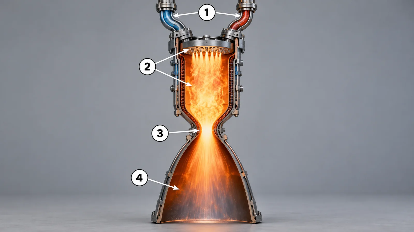
Passing that gas through a nozzle, a tube that narrows and then widens, speeds it up. Gas reaches sound speed at the narrowest point, the "throat", and keeps accelerating in the widening section (a standard textbook description). NASA Glenn notes that liquid and solid rockets carry their propellants on board and take in no outside air.Sourced[Ref. 1]
View original SVG, values and sources
Original SVG reference: Conceptual diagram (vector drawing). Nozzle cross-section and the thrust equation. "Gas goes backward" is the whole idea. The equation is the basic form in the NASA Glenn explanation.
It does not push against air. A rocket moves by the reaction to the gas it throws out, so it works in the airless vacuum of space. As the next section shows, vacuum actually lets the same propellant deliver more thrust, because the outside pressure no longer pushes back.
(1) Reading the thrust equation
The thrust equation in the NASA Glenn explanation is F = ṁ × Ve + Ae × (pe − p0).Sourced[Ref. 1] The first term is "how much gas per second (ṁ), at what speed (Ve)" and is the star of the show. The second multiplies the nozzle exit area (Ae) by the difference between the exit gas pressure (pe) and the outside pressure (p0). Where p0 is large, at sea level, this term shrinks; in vacuum (p0 ≈ 0) it grows.
You do not need to memorize symbols. Remember that "amount per second × speed" is the core of thrust and "outside pressure" is a correction. It is like water from a hose: the force comes mainly from how much water leaves per second and how fast, with the surrounding pressure having a small effect. Where the analogy stops: water is almost incompressible, while rocket gas expands as it accelerates, so the nozzle shape matters.
3. Thrust and specific impulse: sea level versus vacuum
Engine performance starts with two numbers. Thrust is how hard the engine pushes. Specific impulse is how long a given amount of propellant can keep up that push. NASA Glenn defines specific impulse (Isp) as thrust divided by the weight flow rate of propellant, and notes that the unit comes out as seconds.Sourced[Ref. 1]
In this series, specific impulse is the "fuel economy" of the propellant. An Isp of 452 seconds means 1 kg of propellant can supply 1 kilogram-force of thrust for 452 seconds. The larger the number, the farther the same propellant can take you. Where the analogy stops: a car's fuel economy is distance per fuel, whereas specific impulse is a time per unit of propellant weight and is not directly a distance.
(1) A published example: the RS-25
L3Harris publishes values for the RS-25 (the Space Shuttle main engine line, now used on SLS) at 109% power: thrust of 512,300 lbf in vacuum and 418,000 lbf at sea level; specific impulse of 452 s in vacuum and 366 s at sea level (company-stated).Sourced[Ref. 2] For the same engine, sea-level thrust is about 18% lower than vacuum thrust and specific impulse about 19% lower.Our calculation (418,000 / 512,300 = 0.816; 366 / 452 = 0.810)
Why the gap? Using the second term of the thrust equation, the sea-level-to-vacuum difference is roughly Ae × p0 (assuming the flow stays attached inside the nozzle). Dividing the 94,300 lbf gap by sea-level pressure, 14.7 psi, gives an exit area of about 6,400 square inches, or a diameter of about 90 inches (about 2.3 m) if we treat it as a circle.Our calculation L3Harris lists the engine diameter as 96 inches and the area ratio (exit area / throat area) as 69:1,Sourced[Ref. 2] so the estimate is consistent.
More detail: working out mass flow and exhaust velocity
Dividing the 512,300 lbf vacuum thrust by 452 s gives about 1,133 lb (about 514 kg) of propellant per second. The sea-level numbers give 418,000 / 366 = 1,142 lb/s, a difference of under 1% that comes from rounding of the published values.Our calculation Multiplying specific impulse by g0 = 9.80665 m/s² gives the effective exhaust velocity: 452 × 9.80665 = 4,433 m/s.Our calculation This folds the Ve and (pe − p0) terms into one effective speed (NASA Glenn defines Isp = Ve / g0).Sourced[Ref. 1] Throwing about 514 kg per second at about 4.4 km/s gives about 2,280 kN, the same level as the published vacuum thrust.Our calculation
Specific impulse is efficiency and thrust is force; they are separate quantities. Electric propulsion such as ion engines, for example, combines high specific impulse with very small thrust (see our explainer on electric propulsion). And because values change with conditions, comparing a sea-level thrust with a vacuum specific impulse is another source of error.
4. Liquid, solid and hybrid
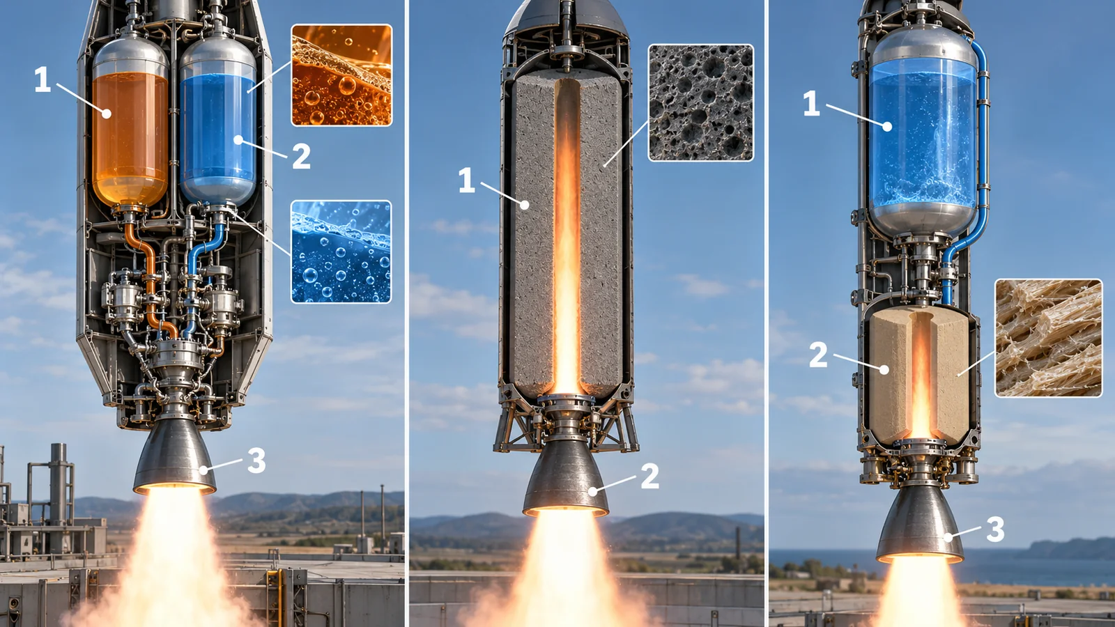
Chemical rockets fall into three groups according to how the propellants are stored. A liquid rocket keeps fuel and oxidizer in separate tanks and sends them to the chamber with pumps and valves. A solid rocket packs a fuel-oxidizer mixture, cast solid, into a case and burns from the inside after ignition. A hybrid combines a liquid oxidizer with a solid fuel.
View original SVG, values and sources
Original SVG reference: Conceptual diagram (vector drawing). Schematic of liquid, solid and hybrid engines; not the structure of a real engine. The shape of the central port in a solid motor varies by design.
The table gives an example of each, and what stands out from a materials viewpoint.
| Type | Example (source) | Materials viewpoint |
|---|---|---|
| Liquid | Merlin (liquid oxygen and RP-1; SpaceX) and RS-25 (hydrogen and oxygen; L3Harris)Sourced[Refs. 3, 2] | Many part types: tanks, pipes, pumps and chamber. Cryogenic, hot, hydrogen- and oxygen-facing duties differ by part (Section 7). |
| Solid | SLS solid rocket booster: five segments, steel cases, PBAN propellant, 3.6 million pounds of thrust each, 126 seconds of operation (NASA)Sourced[Ref. 21] | The propellant is itself a polymer composite. The Space Shuttle-era reference propellant is recorded as an 86% by weight solids ammonium perchlorate / aluminum / PBAN formulation (JPL, 1973).Sourced[Ref. 22] Simple structure, but hard to design for stopping mid-burn (general remark; our commentary). |
| Hybrid | First demonstrated in 1933 by Russia's GIRD-09. A 2023 review lists advantages such as safety and controllability, yet states that industrial use and in-space validation do not yet exist.Sourced[Ref. 23] | Burn rate of the solid fuel (regression rate) and scale-up are cited as challenges (gist of the review). The ECSS general requirements for propulsion (ECSS-E-ST-35C Rev.1) state that hybrid propulsion is not covered in the present issue.Sourced[Ref. 24] |
A liquid engine can change power or restart because valves control the flow of fuel and oxidizer (SpaceX says the Falcon 9 second-stage engine "can be restarted multiple times"),Sourced[Ref. 3] but it needs pumps, valves and plumbing. A solid motor is simple, because the propellant is just packed into a case, but its flow cannot be changed freely once burning (general remark; our commentary).
5. Propellants: kerosene, methane, hydrogen
A liquid propellant is a pair: an oxidizer (what the fuel burns with) and a fuel. The oxidizer is most often liquid oxygen (boiling point 90.188 K at normal pressure; density 1,141.2 kg/m³).Sourced[Ref. 7] The fuel is mainly one of three: kerosene (RP-1), methane or hydrogen.
| Fuel | Boiling point (normal pressure) | Liquid density | Engine examples (company statements) | Materials and cooling |
|---|---|---|---|---|
| RP-1 (rocket kerosene) | Liquid at room temperature | About 808 kg/m³ (converted from an SP-125 example) | Merlin (SpaceX)Sourced[Ref. 3] | Easy to handle, but heating on the wall leaves carbon deposits (coking). In tests, deposits were large at wall temperatures of 600 to 800 K and peaked near 700 K.Sourced[Ref. 14] |
| Methane (including LNG) | 111.67 K (about −161.5 °C) | 422.36 kg/m³ | Raptor (SpaceX; methane-oxygen staged combustion) and BE-4 (Blue Origin; liquefied natural gas and oxygen)Sourced[Refs. 4, 5] | A 1979 NASA study found the highest regeneratively cooled chamber pressure with oxygen/methane, attributing RP-1's lower limit to its low decomposition temperature.Sourced[Ref. 15] |
| Hydrogen | 20.369 K (about −252.8 °C) | 70.848 kg/m³ | RS-25 (L3Harris), LE-9 (MHI), BE-3U (Blue Origin)Sourced[Refs. 2, 6, 5] | Extremely light and cold. Needs tank insulation and care about hydrogen embrittlement of metals (see our explainer on liquid hydrogen). |
Boiling points and liquid densities are NIST Chemistry WebBook values (saturated liquid at 0.101325 MPa).Sourced[Ref. 7] The RP-1 density is our conversion of 50.45 lb/ft³ from a NASA SP-125 design example; the actual density depends on temperature and grade, and a specification value was not checked here.Our calculation[Ref. 8]
(1) Light hydrogen takes up volume
Tank size follows the volume of propellant, not its mass. So let us calculate the mean density of fuel and oxygen together: mean density = (1 + O/F) / (1/fuel density + (O/F)/oxygen density), where O/F is the mass of oxygen divided by the mass of fuel. The RS-25 is published with O/F = 6.0,Sourced[Ref. 2] which gives a hydrogen-oxygen mean density of about 361 kg/m³.Our calculation
In the NASA SP-125 worked example, RP-1 burns with oxygen at O/F = 2.35, with oxygen at 71.38 lb/ft³ and RP-1 at 50.45 lb/ft³,Sourced[Ref. 8] giving a mean density of about 1,017 kg/m³.Our calculation The hydrogen-oxygen pair (361 kg/m³) is about 1/2.8 of that.Our calculation Put differently, for the same propellant mass the hydrogen-oxygen tanks must be about 2.8 times larger in volume.
Hydrogen tends to give a high specific impulse for a given mass of propellant (the RS-25 vacuum value is 452 s),Sourced[Ref. 2] but it is bulky, needs large tanks and needs insulation. Kerosene and methane are denser and fit in smaller tanks. Which is better depends on the stage's role (lift-off or upper stage), vehicle design and cost, so this article does not rank them (staging is covered in our rocket basics explainer).
More detail: what is coking?
When a hydrocarbon such as kerosene meets a hot wall during regenerative cooling (cooling the wall with the fuel itself, Section 7), it can decompose into carbon-rich deposits called coke. Coke conducts heat poorly, so the wall gets hotter and cooling worsens. NASA tests ran RP-1 and propane through heated copper tubes at 136 to 340 atm and wall temperatures of 422 to 811 K and measured the deposits. For RP-1 the deposits were large at wall temperatures of 600 to 800 K, peaked near 700 K and rose slightly with pressure.Sourced[Ref. 14] Methane is often described as better in this respect, but this article did not confirm comparison data from real engines.
6. Pumps and engine cycles
A liquid engine raises propellant pressure with pumps before feeding the chamber. The RS-25 chamber pressure is published as 2,994 psia (about 20.6 MPa)Sourced[Ref. 2]Our calculation (2,994 × 6.895 kPa). Higher pressure lets a smaller engine deliver more thrust (general remark). The pumps are spun by a turbine, and the engine "cycle" depends on where the gas that drives the turbine comes from.
- Gas-generator cycle: a small separate burner uses part of the propellant to drive the turbine, and the used gas is dumped. SpaceX describes Merlin as a gas-generator cycle.Sourced[Ref. 3] The dumped gas adds no thrust, so specific impulse tends to be lower (general remark).
- Expander cycle: fuel that has warmed while cooling the wall turns to gas and spins the turbine. MHI calls the LE-9 an "expander bleed cycle" and says it is the first in the world scaled up to high thrust (company claim).Sourced[Ref. 6] Blue Origin calls the BE-3U an "open-expander cycle".Sourced[Ref. 5] NASA Glenn notes that in an expander cycle the transfer of heat to the fuel governs efficiency, so the chamber liner needs the highest possible thermal conductivity.Sourced[Ref. 10]
- Staged-combustion cycle: the turbine gas is made in a separate burner called a preburner, and the used gas then also burns in the main chamber. A preburner can be fuel-rich or oxygen-rich.Sourced[Ref. 16] NASA material lists the RS-25 as a staged-combustion engine,Sourced[Ref. 10] Blue Origin describes the BE-4 as "the first oxygen-rich staged combustion engine made in the U.S." (company claim),Sourced[Ref. 5] and SpaceX describes Raptor as a methane-oxygen staged-combustion engine.Sourced[Ref. 4]
A cycle looks like a mechanical design choice, but it actually sets the demands on materials. In an expander cycle, the heat passed from wall to fuel is the very power source, so a wall material of high thermal conductivity is needed (the reason NASA Glenn developed GRCop-42 from GRCop-84).Sourced[Ref. 10] In oxygen-rich staged combustion the turbine sees hot gas rich in high-pressure oxygen, so metal ignition becomes the main concern. A NASA report says the design criteria for preventing metal ignition in an oxygen-rich preburner are met through material selection and well-mixed gases.Sourced[Ref. 16] (Section 7 gives more.)
7. Engine materials: wall, pumps, nozzle
Now to the heart of it for materials engineers. Each part of the engine faces a different enemy. Here is the overall map first, then each part in turn.
(1) The chamber wall: carry the heat and survive repeated cycles
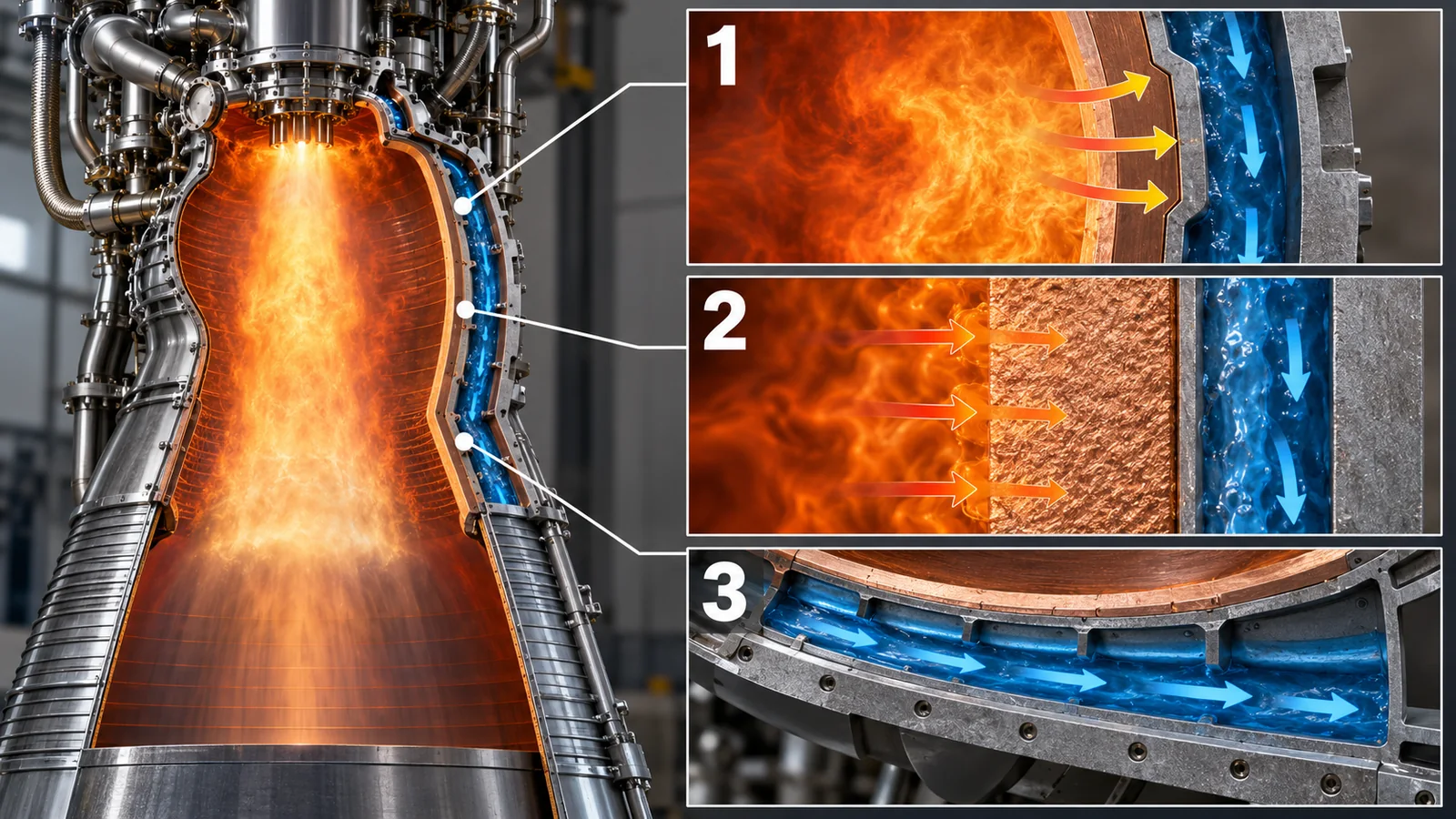
A regeneratively cooled wall sits between two extremes: combustion gas at thousands of kelvin on the inside and cold fuel on the outside. A NASA Glenn technical brief says the liner sees heat flux above 10 MW/m², a temperature difference above 500 °C across 1 mm, and a strain difference above 1% between the channel side and the hot wall. Each firing adds one low-cycle-fatigue cycle; the count is as few as one for an expendable first-stage engine and up to several thousand for a reusable vehicle or attitude-control engine. Creep and "thermal ratcheting" (the wall slowly bowing toward the cooling channel) wear it out in the end.Sourced[Ref. 9]
View original SVG, values and sources
Original SVG reference: Conceptual diagram (vector drawing). Schematic of a regeneratively cooled wall. Layer thicknesses and channel counts are illustrative, not the dimensions of a real engine. Numbers are from the NASA Glenn technical brief.
The classic wall material is a copper alloy. The liner of the Space Shuttle Main Engine (SSME) combustion chamber was NARloy-Z, an alloy of 96.5% copper, 3% silver and 0.5% zirconium by weight. Cooling channels are machined into the outside of the liner and then closed out by electroforming (growing thick metal by electroplating). A 1987 NASA report says this design and material combination can withstand a throat heat flux of the order of 163 MW/m².Sourced[Ref. 11]
In 1977 NASA Lewis ran 21 of 22 cylindrical liners, made of oxygen-free copper, Amzirc and NARloy-Z, to failure with hydrogen and oxygen (O/F 6.0), an average throat heat flux of 54 MW/m² and liquid-hydrogen cooling. Every failure took the same form: the channel wall thinned at its centre and finally ruptured in tension. The cyclic-life ranking by temperature did not agree with published rankings from simple isothermal strain tests.Sourced[Ref. 12] It shows why testing in real thermal cycles matters.
NASA later developed GRCop (Glenn Research Copper), a copper-chromium-niobium alloy. GRCop-84 has 14% Cr₂Nb precipitates dispersed in a pure-copper matrix.Sourced[Ref. 9] GRCop-42 (Cu-4 at.% Cr-2 at.% Nb) halves the chromium and niobium, giving up some strength for higher thermal conductivity, and was made for expander-cycle engines.Sourced[Ref. 10] GRCop-42 has also been built by powder bed fusion (metal 3D printing) and hot-fire tested.Sourced[Ref. 13] (This is covered in our explainer on additive manufacturing for space.)
According to a 1987 NASA report, NARloy-Z was made by a specialized route of vacuum melting and vacuum centrifugal casting. The original supplier had dismantled the equipment, and production had stopped after the cast cylinders required for the SSME program. NASA made an alloy of the same composition, "NASA-Z", by conventional melting, casting and forging, compared composition, microstructure, tensile properties, low-cycle-fatigue life and hot-fire life, and found similar characteristics.Sourced[Ref. 11] The point for materials engineers: a material's performance rests not only on composition but on the process and equipment that can make it (our commentary).
(2) Cooling with kerosene: coking
The challenge in cooling with kerosene is the coking we saw in Section 5. A 1979 NASA study compared the regeneratively cooled chamber-pressure limits for oxygen/methane, oxygen/propane and oxygen/RP-1. The limit was highest with oxygen/methane, and the oxygen/RP-1 designs had to rely on a carbon layer and similar measures.Sourced[Ref. 15] So the chemical stability of the coolant is part of the wall design, not just the wall material.
(3) Turbopumps and hydrogen
Turbine and impeller parts in the pumps use high-strength, heat-resistant nickel-based superalloys. A 1993 NASA report names Inconel 718 and NASA-23 as high-temperature metallic alloys widely used in the turbomachinery of the Space Shuttle main engine.Sourced [Ref. 19] Metals exposed to hydrogen raise the concern of hydrogen embrittlement, where hydrogen enters the metal and lowers its ductility and toughness. A 2016 NASA technical memorandum compiles experimental data on gaseous hydrogen environment embrittlement for many metals and describes screening methods.Sourced[Ref. 20] Yet in the 1993 hot-hydrogen exposure tests (450 to 1100 °C, 1 to 5 atm of hydrogen), Inconel 718 and NASA-23 showed no weight change or surface change.Sourced[Ref. 19] The outcome depends on temperature, pressure and stress, so "resistant" or "susceptible" cannot be said in one breath. (Cryogenic hydrogen handling is covered in our liquid hydrogen explainer.)
(4) High-pressure oxygen and metal ignition
Under high pressure, oxygen can burn even metals that normally do not burn. NASA's White Sands Test Facility developed test methods such as particle impact, frictional heating and promoted combustion to judge whether alloys suit oxygen-enriched environments.Sourced[Ref. 18] In the promoted combustion test, an igniter is placed at the bottom of a rod-shaped specimen and the test checks whether burning spreads; it is Test 17 of the NASA standard NASA-STD-6001. At Marshall, stainless steels 304L and 321, Haynes 214 and Inconel 718 were tested in hot 100% oxygen, and the pressure limit for burn-free use dropped as temperature rose.Sourced[Ref. 17] In an oxygen-rich turbine, results like these shape the choice of materials and the design of gas mixing.
(5) The nozzle extension: cooled by radiation
Engines for vacuum use widen the nozzle to raise efficiency. SpaceX says the Merlin Vacuum has a large expansion nozzle, a regeneratively cooled chamber and a radiatively cooled expansion nozzle (company statement).Sourced[Ref. 3] Without air there is no convective cooling, so the hot metal sheds heat as infrared radiation. (How heat escapes in vacuum is covered in our explainer on thermal control materials and radiative cooling.)
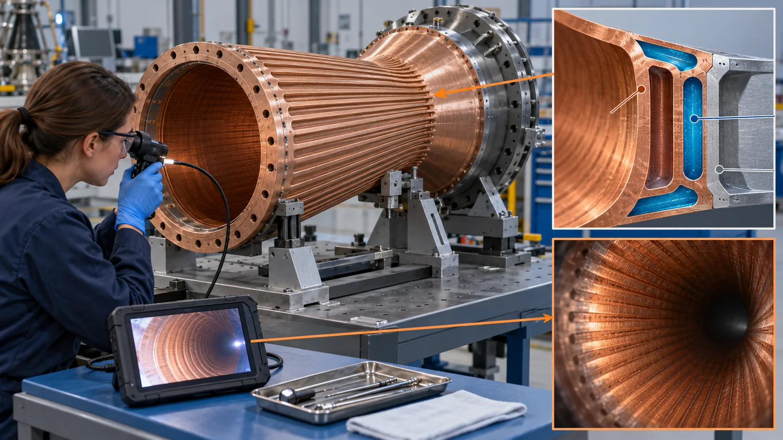
As the Ellis technical brief says, a liner's low-cycle-fatigue count ranges from one for an expendable engine to several thousand for a reusable one.Sourced[Ref. 9] The same copper alloy faces different questions: an expendable engine only has to survive one firing, while a reusable engine must keep the channel wall from thinning over repeated firings. Both the evaluation and the optimization of the composition are far harder for the latter. The NASA standard NASA-STD-5012 sets requirements for the strength and life (fatigue and creep) assessment of liquid-fueled engines.Sourced[Ref. 29] The economics of reuse are covered in our reusable rockets explainer.
8. Reading today's engines from published values (checked 17 October 2026)
Finally, here are values companies publish on their official pages, with conditions. Values whose conditions differ cannot be used to rank engines. The "Conditions" column repeats what the page states.
| Engine | Propellants and cycle | Thrust (published) | Specific impulse (published) | Conditions and cautions |
|---|---|---|---|---|
| RS-25 | Hydrogen/oxygen, staged combustion | Vacuum 512,300 lbf; sea level 418,000 lbf | Vacuum 452 s; sea level 366 s | 109% power. L3Harris (company-stated)Sourced[Ref. 2] |
| LE-9 | Hydrogen/oxygen, expander bleed | Vacuum "150 ton" (MHI's notation; about 1,471 kN if read as tonnes-force; our conversion) | Vacuum 425 s | Two or three on the H3 first stage. MHI (company-stated)Sourced[Ref. 6] |
| Merlin | RP-1/oxygen, gas generator | 845 kN (190,000 lbf) | Not found on the page | Shown under the "Sea Level" tab. SpaceX (company-stated)Sourced[Ref. 3] |
| Merlin Vacuum | RP-1/oxygen, gas generator | 981 kN (220,500 lbf) | Not found on the page | Shown under the "Vacuum" tab. SpaceX (company-stated)Sourced[Ref. 3] |
| Raptor | Methane/oxygen, staged combustion | 250 tf (551 klbf) | Not found on the page | Sea level or vacuum not stated. SpaceX (company-stated)Sourced[Ref. 4] |
| BE-4 | LNG/oxygen, oxygen-rich staged combustion | 640,000 lbf (2,846 kN); throttles to 220,000 lbf (978 kN) | Not found on the page | Sea level or vacuum not stated. Blue Origin (company-stated)Sourced[Ref. 5] |
| BE-3U | Hydrogen/oxygen, open expander | 200,000 lbf (890 kN); throttles to 100,000 lbf (445 kN) | Not found on the page | For the New Glenn second stage. Blue Origin (company-stated)Sourced[Ref. 5] |
Checked on 17 October 2026. Published values can be updated. This article could not find specific-impulse values on the SpaceX or Blue Origin pages.
For materials, the thrust-to-weight ratio (thrust divided by engine mass) is a useful gauge. L3Harris publishes the RS-25 mass as 7,775 lb,Sourced[Ref. 2] and dividing the vacuum thrust by it gives about 66.Our calculation MHI lists the LE-9 at 2,400 kg with vacuum thrust "150 ton" (about 1,471 kN if read as tonnes-force),Sourced[Ref. 6] giving about 62.Our calculation We could not confirm whether the published masses are dry masses or include accessories, so we do not compare the two values. The gauge simply shows the direction: to carry large thrust on a light structure, walls and pumps are made thin and light, which leaves a smaller margin in the materials (our commentary).
9. How to read the yardsticks and standards
Engine performance and reliability are measured with several yardsticks. Thrust and specific impulse are measured in hot-fire tests and must always come with sea level or vacuum and the power level. Life is confirmed by fatigue and creep analysis and tests, and by the number of hot-fire tests. Materials compatibility with oxygen and hydrogen is confirmed by testing. Propellant quality has its own standards. What matters is knowing what each yardstick does and does not measure.
| What is assessed | Typical test or method (name, source) | Standards and guidance (ECSS, NASA, ISO, etc.) | Reading notes |
|---|---|---|---|
| Thrust and specific impulse | Engine hot-fire test. The definition of specific impulse is in the NASA Glenn explanation.Sourced[Ref. 1] | ECSS-E-ST-35C Rev.1 "Propulsion general requirements" (6 March 2009) and ECSS-E-ST-35-03C "Liquid propulsion for launchers" (13 May 2011).Sourced[Refs. 24, 25] A clause fixing how to measure specific impulse was not checked (could not be confirmed). | Sea level or vacuum, power level, chamber pressure. Company-stated values differ from third-party measurements. |
| Structural strength and life (fatigue, creep) | Strength and life analysis and testing. Liner life is dominated by low-cycle fatigue.Sourced[Ref. 9] | NASA-STD-5012 (Version C, change dated 31 December 2025; Active): strength and life assessment requirements for liquid-fueled engines.Sourced[Ref. 29] | A NASA standard. Its application to commercial vehicles depends on contracts (could not be confirmed). The requirement values were not checked here. |
| Material compatibility with oxygen | Promoted combustion, frictional ignition and particle impact tests (NASA White Sands and Marshall).Sourced[Refs. 18, 17] | NASA-STD-6001 (Version B with Change 3, change dated 9 June 2025; Active): requirements and test procedures for flammability, offgassing and compatibility of materials for space vehicles; Test 17 is promoted combustion.Sourced[Refs. 30, 17] | The burn limit shifts with test conditions (temperature, pressure, specimen shape). Do not label a material simply "non-burning". |
| Propellant quality | Composition limits plus sampling and test methods | ISO 15859-1 (oxygen), -2 (hydrogen) and -8 (kerosine), all published June 2004 and confirmed.Sourced[Refs. 31, 32, 33] Rocket kerosene is covered by MIL-DTL-25576 (RP-1 and RP-2).Sourced[Ref. 34] A part for methane could not be found. | MIL-DTL-25576 was confirmed at revision E (14 April 2006) on a document repository; the latest revision could not be confirmed. |
| Cleanliness and compatibility testing | Cleanliness requirements for parts and systems; compatibility tests of materials with propellants | ECSS-E-ST-35-06C Rev.2 (7 April 2020) and ECSS-E-ST-35-10C (6 March 2009).Sourced[Refs. 27, 28] | Only titles and scope were checked. Requirement values are not given. |
| Solid rocket motors | Propellant and case tests, motor firing tests | ECSS-E-ST-35-02C "Solid propulsion for spacecrafts and launchers" (8 October 2010).Sourced[Ref. 26] | Only the title and scope were checked. |
| Life of reusable engines | Could not be confirmed (flight counts are company-reported records) | Could not be confirmed (no common standard for the life of reusable engines was found in this survey) | A count of flights means different things under different test and maintenance conditions. |
| ASTM standards | — | No relevant ASTM standard could be confirmed (the ASTM website was not opened for this article) | — |
The arrangement of the table is Our calculation (organizing). Numbers, titles and status were checked on ecss.nl, the NASA Technical Standards System and ISO catalogue pages (17 October 2026). Standard texts were not read; only titles and scope are given.
Reading notes (for materials engineers)
- Ground tests and flight records differ. Ground hot-fire tests run at sea-level pressure. Vacuum values come from design and correction, and conditions differ from flight data.
- Company-stated values differ from independent verification. Every thrust and specific-impulse figure here is company-published. Where the page does not say sea level or vacuum, values cannot be compared.
- Check whether a standard is a recommendation or a requirement. NASA-STD-5012 and NASA-STD-6001 are standards NASA uses; whether they apply to a commercial engine depends on contracts or certification. ECSS standards also become requirements only when a project adopts them by contract (general remark).
- Qualification differs from acceptance testing. Qualification tests show that a new design meets the requirements; acceptance tests show that an individual unit is good. (See our explainer on reading space-materials evaluations.)
10. Glossary
- Thrust
- The force with which the engine pushes the vehicle. Measured in newtons (N) or pounds-force (lbf).
- Specific impulse (Isp)
- Thrust divided by the weight flow of propellant. Unit: seconds. The "fuel economy" of the propellant.
- Mass flow rate (ṁ)
- Mass of propellant (gas) passing through the engine each second.
- Effective exhaust velocity
- Specific impulse times gravitational acceleration: an "effective" exit speed that includes the pressure term.
- Propellant
- The material a rocket expels; the combination of fuel and oxidizer.
- Oxidizer
- The source of oxygen that lets fuel burn. Liquid oxygen is the usual one.
- LOX
- Liquid oxygen. Boiling point 90.188 K at normal pressure.
- RP-1
- Rocket Propellant-1: kerosene refined for rocket use.
- LNG
- Liquefied natural gas, mostly methane.
- O/F (mixture ratio)
- Mass of oxidizer divided by mass of fuel.
- Combustion chamber
- Where propellants burn into hot, high-pressure gas.
- Nozzle / throat
- The converging-diverging tube that accelerates the gas. The narrowest point is the throat.
- Area ratio
- Nozzle exit area divided by throat area.
- Regenerative cooling
- Cooling the wall with a propellant such as the fuel, then using the warmed propellant as fuel.
- Turbopump
- A turbine-driven pump that raises propellant pressure and feeds the chamber.
- Gas-generator cycle
- A cycle in which a small separate burner drives the turbine and the used gas is dumped.
- Expander cycle
- A cycle in which fuel warmed in the wall turns to gas and drives the turbine.
- Staged-combustion cycle
- A cycle in which a preburner drives the turbine and the used gas is also burned in the main chamber.
- Preburner
- A small burner ahead of the main chamber that makes the turbine gas.
- Coking
- Decomposition of a hydrocarbon on a hot wall leaving carbon deposits (coke).
- Low-cycle fatigue
- Fatigue from a small number of large strain cycles. One firing is one cycle.
- Thermal ratcheting
- Progressive, non-recovering deformation of a wall with each heating and cooling cycle.
- Hydrogen embrittlement
- Loss of ductility or toughness when hydrogen enters a metal.
- NARloy-Z
- The copper alloy (Cu-Ag-Zr) used for the SSME chamber liner.
- GRCop
- NASA Glenn's copper-chromium-niobium alloys, such as GRCop-84 and GRCop-42.
- Electroforming
- Building a shape by growing thick metal through electroplating.
- PBAN
- A polybutadiene-acrylonitrile polymer used as a binder in solid propellant.
- SSME / SLS
- Space Shuttle Main Engine / Space Launch System.
- ECSS
- European Cooperation for Space Standardization.
11. References
- NASA Glenn Research Center "Specific Impulse" (Beginner's Guide to Aeronautics) (checked 17 October 2026) — www1.grc.nasa.gov/beginners-guide-to-aeronautics/specific-impulse
- L3Harris "RS-25 engine" (engine specifications; 109% power level) (company-stated values; checked 17 October 2026) — l3harris.com/all-capabilities/rs-25-engine
- SpaceX "Falcon 9" (vehicle and Merlin engine pages) (company-stated values; checked 17 October 2026) — www.spacex.com/vehicles/falcon-9/
- SpaceX "Starship" (Raptor engine) (company-stated values; checked 17 October 2026) — www.spacex.com/vehicles/starship/
- Blue Origin "Engines" (BE-4, BE-3U and others) (company-stated values; checked 17 October 2026; the page does not say whether thrust is sea-level or vacuum) — www.blueorigin.com/engines
- Mitsubishi Heavy Industries "H3 First Stage Engine LE-9" (company-stated values; checked 17 October 2026) — www.mhi.com/products/space/first_stage_engine_le-9.html
- NIST "NIST Chemistry WebBook: Thermophysical Properties of Fluid Systems" (methane C74828, oxygen C7782447, hydrogen C1333740) (density and boiling point of the saturated liquid at 0.101325 MPa; checked 17 October 2026) — webbook.nist.gov/chemistry/fluid/
- Huzel D. K., Huang D. H. "Design of Liquid Propellant Rocket Engines", NASA SP-125 (2nd ed.) (NTRS; the RP-1 density of 50.45 lb/ft³ is a value used in a worked design example) — ntrs.nasa.gov/citations/19710019929
- Ellis D. L. (NASA Glenn) "Cu-Cr-Nb-Zr Alloy for Rocket Engines and Other High-Heat-Flux Applications", NASA Tech Briefs (Aug. 2013) — ntrs.nasa.gov/citations/20130014444
- Ellis D. L. (NASA Glenn) "Conductivity of GRCop-42 Alloy Enhanced" (2004) — ntrs.nasa.gov/citations/20050192166
- Kazaroff J. M., Repas G. A. "Conventionally cast and forged copper alloy for high-heat-flux thrust chambers", NASA TM (1987) — ntrs.nasa.gov/citations/19870007469
- Quentmeyer R. J. "Experimental fatigue life investigation of cylindrical thrust chambers", NASA (1977) — ntrs.nasa.gov/citations/19770024295
- Gradl P. R. et al. (NASA Marshall) "GRCop-42 Development and Hot-fire Testing Using Additive Manufacturing Powder Bed Fusion for Channel-Cooled Combustion Chambers" (2019) — ntrs.nasa.gov/citations/20190030433
- Roback R., Szetela E. J., Spadaccini L. J. "Deposit formation in hydrocarbon rocket fuels", NASA (1981) — ntrs.nasa.gov/citations/19810021741
- Cook R. T. "Advanced cooling techniques for high-pressure hydrocarbon-fueled engines", NASA (1979) — ntrs.nasa.gov/citations/19800008881
- Schoenman L. "Fuel/oxidizer-rich high-pressure preburners", NASA (1981) — ntrs.nasa.gov/citations/19820002372
- Engel C. D., Herald S. D., Davis S. E. (NASA Marshall) "Promoted Metals Combustion at Ambient and Elevated Temperatures" (2005) — ntrs.nasa.gov/citations/20050245285
- Stoltzfus J. M., Gunaji M. V. (NASA White Sands) "Test methods for determining the suitability of metal alloys for use in oxygen-enriched environments" (1991) — ntrs.nasa.gov/citations/19920013202
- Zee R., Chin B., Inamdar R. "Hot hydrogen testing of metallic turbo pump materials", NASA (1993) — ntrs.nasa.gov/citations/19940019593
- Lee J. A., Woods S. (NASA Marshall) "Hydrogen Embrittlement", NASA TM (2016) — ntrs.nasa.gov/citations/20160005654
- NASA "SLS (Space Launch System) Solid Rocket Booster" fact sheet (July 2024) — www.nasa.gov/wp-content/uploads/2024/07/sls-4904-sls-solid-rocket-booster-fact-sheet-jul2024-508.pdf
- Jet Propulsion Laboratory "Alternate propellants for the space shuttle solid rocket booster motors", JPL TM 33-649 (1973) — ntrs.nasa.gov/citations/19740002597
- Glaser C., Hijlkema J., Anthoine J. "Bridging the Technology Gap: Strategies for Hybrid Rocket Engines", Aerospace 10(10), 901 (2023), DOI 10.3390/aerospace10100901 — doi.org/10.3390/aerospace10100901
- ECSS ECSS-E-ST-35C Rev.1 "Propulsion general requirements" (6 March 2009) (checked 17 October 2026; listed under Active Standards) — ecss.nl/standard/ecss-e-st-35c-rev-1-propulsion-general-requirements/
- ECSS ECSS-E-ST-35-03C "Liquid propulsion for launchers" (13 May 2011) — ecss.nl/standard/ecss-e-st-35-03c-liquid-propulsion-for-launchers-13-may-2011/
- ECSS ECSS-E-ST-35-02C "Solid propulsion for spacecrafts and launchers" (8 October 2010) — ecss.nl/standard/ecss-e-st-35-02c-solid-propulsion-for-spacecrafts-and-launchers-8-october-2010/
- ECSS ECSS-E-ST-35-06C Rev.2 "Cleanliness requirements for spacecraft propulsion hardware" (7 April 2020) — ecss.nl/standard/ecss-e-st-35-06c-rev-2-cleanliness-requirements-for-spacecraft-propulsion-hardware-7-april-2020/
- ECSS ECSS-E-ST-35-10C "Compatibility testing for liquid propulsion systems" (6 March 2009) — ecss.nl/standard/ecss-e-st-35-10c-compatibility-testing-for-liquid-propulsion-systems/
- NASA NASA-STD-5012 "Strength and Life Assessment Requirements for Liquid-Fueled Space Propulsion System Engines" (Version C, change date 31 December 2025) (NASA Technical Standards System; Active; checked 17 October 2026) — standards.nasa.gov/standard/NASA/NASA-STD-5012
- NASA NASA-STD-6001 "Flammability, Offgassing, and Compatibility Requirements and Test Procedures" (Version B with Change 3, change date 9 June 2025) (NASA Technical Standards System; Active; checked 17 October 2026) — standards.nasa.gov/standard/NASA/NASA-STD-6001
- ISO ISO 15859-1:2004 "Space systems — Fluid characteristics, sampling and test methods — Part 1: Oxygen" (Published, confirmed; checked 17 October 2026) — www.iso.org/standard/37276.html
- ISO ISO 15859-2:2004 "… Part 2: Hydrogen" (Published, confirmed; checked 17 October 2026) — www.iso.org/standard/37277.html
- ISO ISO 15859-8:2004 "… Part 8: Kerosine propellant" (Published, confirmed; checked 17 October 2026) — www.iso.org/standard/37283.html
- EverySpec (document repository) MIL-DTL-25576E "Propellant, Rocket Grade Kerosene" (14 Apr 2006) (covers two grades, RP-1 and RP-2; confirmed on a document repository, not the issuing body; whether a newer revision exists could not be confirmed) — everyspec.com/MIL-SPECS/MIL-SPECS-MIL-DTL/MIL-DTL-25576E_16072/
12. Claim-to-source audit
| Claim in the text | Basis | Type |
|---|---|---|
| Definition of specific impulse (thrust / weight flow, unit seconds); the thrust equation F = ṁVe + Ae(pe − p0); liquid and solid rockets carry propellants and take in no outside air | NASA Glenn explanation Reference 1 https://www1.grc.nasa.gov/beginners-guide-to-aeronautics/specific-impulse | Sourced |
| RS-25 thrust and specific impulse (109% power, sea level and vacuum), O/F 6.0, chamber pressure 2,994 psia, area ratio 69:1, diameter 96 in, mass 7,775 lb | L3Harris published values (company-stated) Reference 2 https://l3harris.com/all-capabilities/rs-25-engine | Sourced |
| Merlin thrust, propellants and cycle; Merlin Vacuum thrust and radiatively cooled nozzle; Falcon 9 second-stage restart | SpaceX official page (company-stated) Reference 3 https://www.spacex.com/vehicles/falcon-9/ | Sourced |
| Raptor thrust and methane-oxygen staged combustion | SpaceX official page (company-stated) Reference 4 https://www.spacex.com/vehicles/starship/ | Sourced |
| BE-4 and BE-3U thrust, propellants and cycle descriptions | Blue Origin official page (company-stated) Reference 5 https://www.blueorigin.com/engines | Sourced |
| LE-9 propellants, vacuum thrust "150 ton", vacuum specific impulse 425 s, mass 2,400 kg, expander bleed cycle, two or three on the first stage | MHI official page (company-stated) Reference 6 https://www.mhi.com/products/space/first_stage_engine_le-9.html | Sourced |
| Boiling points and saturated-liquid densities of oxygen, methane and hydrogen at normal pressure | NIST Chemistry WebBook Reference 7 https://webbook.nist.gov/chemistry/fluid/ | Sourced |
| The RP-1 density of 50.45 lb/ft³, oxygen at 71.38 lb/ft³ and O/F 2.35 are values from a worked design example in NASA SP-125 | NASA SP-125 (NTRS) Reference 8 https://ntrs.nasa.gov/citations/19710019929 | Sourced |
| Liner heat flux (above 10 MW/m²), temperature difference above 500 °C across 1 mm, strain difference above 1%, low-cycle-fatigue count (one to several thousand), creep and thermal ratcheting, GRCop-84 composition (14% Cr₂Nb) | NASA Tech Briefs (Ellis, 2013) Reference 9 https://ntrs.nasa.gov/citations/20130014444 | Sourced |
| Motivation for GRCop-42 (Cu-4 at.% Cr-2 at.% Nb): higher thermal conductivity for expander cycles | NTRS (Ellis, 2004) Reference 10 https://ntrs.nasa.gov/citations/20050192166 | Sourced |
| NARloy-Z composition (Cu 96.5%, Ag 3%, Zr 0.5%), channel closeout by electroforming, throat heat flux of the order of 163 MW/m², the NASA-Z story | NASA TM (Kazaroff and Repas, 1987) Reference 11 https://ntrs.nasa.gov/citations/19870007469 | Sourced |
| The 1977 cyclic test of 22 cylindrical liners: the failure mode, and a life ranking that did not match isothermal-test rankings | NASA (Quentmeyer, 1977) Reference 12 https://ntrs.nasa.gov/citations/19770024295 | Sourced |
| Powder-bed-fusion build and hot-fire testing of GRCop-42 | NTRS (Gradl et al., 2019) Reference 13 https://ntrs.nasa.gov/citations/20190030433 | Sourced |
| RP-1 coking test results (600 to 800 K, peak near 700 K); comparison of chamber-pressure limits (oxygen/methane highest) | NASA (Roback et al., 1981; Cook, 1979) Reference 14 https://ntrs.nasa.gov/citations/19810021741 Reference 15 https://ntrs.nasa.gov/citations/19800008881 | Sourced |
| Fuel-rich and oxygen-rich preburners exist; design criteria for preventing metal ignition in an oxygen-rich preburner | NASA (Schoenman, 1981) Reference 16 https://ntrs.nasa.gov/citations/19820002372 | Sourced |
| Promoted combustion test (Test 17 of NASA-STD-6001), results in hot oxygen, White Sands test methods | NASA (Engel et al., 2005; Stoltzfus and Gunaji, 1991) Reference 17 https://ntrs.nasa.gov/citations/20050245285 Reference 18 https://ntrs.nasa.gov/citations/19920013202 | Sourced |
| Use of Inconel 718 and NASA-23, hot-hydrogen exposure results, compilation of hydrogen embrittlement data | NASA (Zee et al., 1993; Lee and Woods, 2016) Reference 19 https://ntrs.nasa.gov/citations/19940019593 Reference 20 https://ntrs.nasa.gov/citations/20160005654 | Sourced |
| SLS solid rocket booster data (five segments, steel cases, PBAN, 3.6 million pounds of thrust, 126 s) | NASA fact sheet Reference 21 https://www.nasa.gov/wp-content/uploads/2024/07/sls-4904-sls-solid-rocket-booster-fact-sheet-jul2024-508.pdf | Sourced |
| The Space Shuttle reference solid propellant is an 86% by weight solids AP/Al/PBAN formulation | JPL TM 33-649 (1973) Reference 22 https://ntrs.nasa.gov/citations/19740002597 | Sourced |
| First demonstration of hybrid propulsion (1933), its advantages, and the absence of industrial use and in-space validation | Glaser et al. (2023) Reference 23 https://doi.org/10.3390/aerospace10100901 | Sourced |
| ECSS general requirements for propulsion (hybrid not covered); titles and dates of the standards for liquid (launchers), solid, cleanliness and compatibility testing | ECSS official pages Reference 24 https://ecss.nl/standard/ecss-e-st-35c-rev-1-propulsion-general-requirements/ Reference 25 https://ecss.nl/standard/ecss-e-st-35-03c-liquid-propulsion-for-launchers-13-may-2011/ Reference 26 https://ecss.nl/standard/ecss-e-st-35-02c-solid-propulsion-for-spacecrafts-and-launchers-8-october-2010/ Reference 27 https://ecss.nl/standard/ecss-e-st-35-06c-rev-2-cleanliness-requirements-for-spacecraft-propulsion-hardware-7-april-2020/ Reference 28 https://ecss.nl/standard/ecss-e-st-35-10c-compatibility-testing-for-liquid-propulsion-systems/ | Sourced |
| Numbers, titles, versions and status of NASA-STD-5012 and NASA-STD-6001 | NASA Technical Standards System Reference 29 https://standards.nasa.gov/standard/NASA/NASA-STD-5012 Reference 30 https://standards.nasa.gov/standard/NASA/NASA-STD-6001 | Sourced |
| Numbers, titles and status of ISO 15859 Parts 1 (oxygen), 2 (hydrogen) and 8 (kerosine) | ISO catalogue pages Reference 31 https://www.iso.org/standard/37276.html Reference 32 https://www.iso.org/standard/37277.html Reference 33 https://www.iso.org/standard/37283.html | Sourced |
| Title and date of revision E of MIL-DTL-25576 (rocket-grade kerosene, RP-1 and RP-2) | Document-repository page (EverySpec); not confirmed at the issuing body Reference 34 https://everyspec.com/MIL-SPECS/MIL-SPECS-MIL-DTL/MIL-DTL-25576E_16072/ | Sourced |
| The 94,300 lbf gap, exit area of about 6,400 in² and diameter of about 90 in, mass flow of about 1,133 lb/s, effective exhaust velocity of about 4,433 m/s, about 2,280 kN, chamber pressure of about 20.6 MPa, thrust-to-weight of about 66 and 62, mean densities of 361, 1,017 and 851 kg/m³ and their 1/2.8 ratio | Our calculation (from published values and NIST data; the methane O/F of 4.0 is an assumption) | Our calculation |
| Specific impulse of methane and kerosene engines, a common standard for the life of reusable engines, an ISO standard for methane, ASTM standards | Could not be confirmed in primary sources within this survey, so not stated (this article) | Commentary |
| That the cycle choice sets materials demands; the lesson of lost equipment; firing count and life requirements; the general remark that solids are hard to stop and liquids easy to restart | Our organization and commentary based on the published material | Commentary |
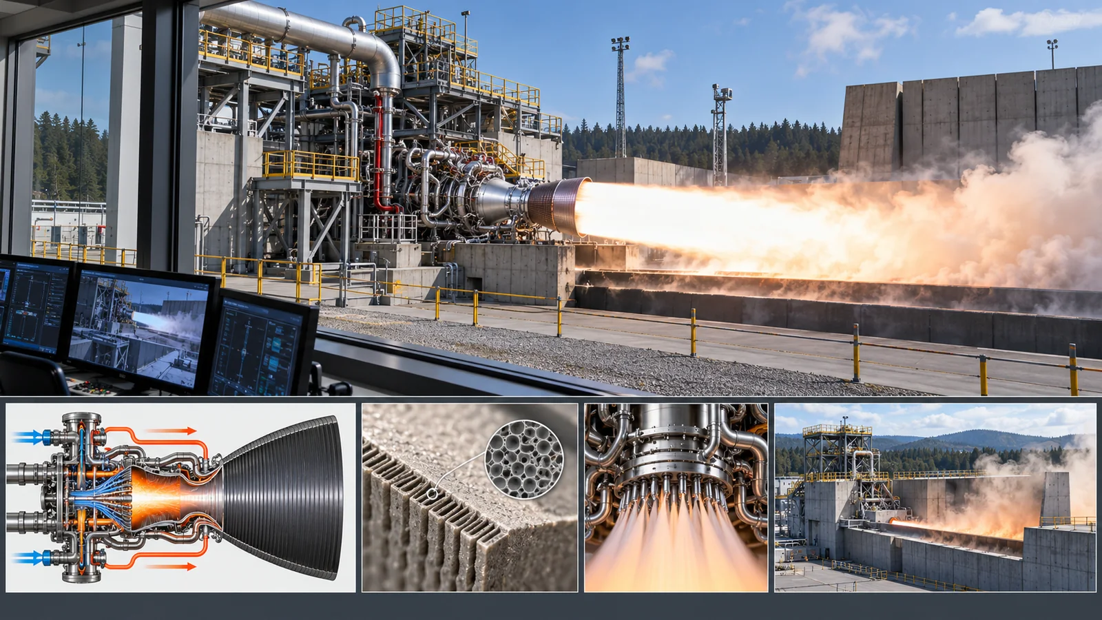
| Figs. 1 and 9 are AI-generated concept images, and Figs. 2 to 8 are explanatory drawings | Note by this article | Commentary |
Last updated: 17 October 2026. Sources are limited to primary materials (NASA, ECSS, NASA standards, ISO, NIST, company pages, peer-reviewed papers). Thrust and specific impulse are company-published values and carry their conditions (sea level, vacuum, power level). Numerical examples (mass flow, area, mean density) are explanatory calculations made for this article. Specific impulse of kerosene and methane engines, a common standard for the life of reusable engines, and an ISO standard for methane could not be confirmed and are not stated. Figs. 1 and 9 are AI-generated concept images and do not depict real facilities or products.