TECHNOLOGY EXPLAINER
Electric Propulsion
— A small push applied for a long time: getting far on little propellant, and the materials inside ion and Hall thrusters
When people think of rockets they picture a huge flame. Yet once a spacecraft is in space, changing its orbit or holding its altitude is increasingly done with electric propulsion: using electricity to accelerate propellant gently and throw it out the back. The push is tiny, but the same amount of propellant yields a much bigger change in speed, so propellant takes a smaller share of the spacecraft's mass. Written for materials engineers who know little about spaceflight, this article explains why electric propulsion is used, why its thrust is small, and how ion thrusters and Hall thrusters differ, using figures from public sources and a few small calculations. The focus is on materials: the grids that ions wear away, the channel walls whose erosion sets thruster life, the tungsten cathode impregnated with barium, how propellants are chosen, and what the plume does to surfaces on the spacecraft.
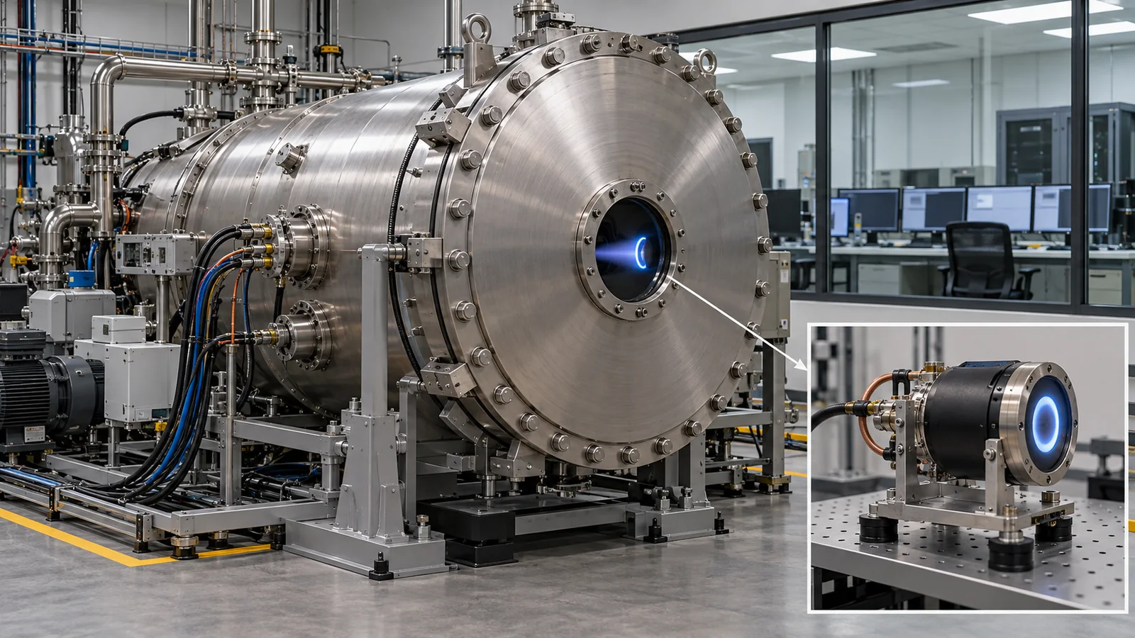
- The short version / what to know first / where this fits in the series
- Why electric propulsion: specific impulse and the rocket equation
- Thrust is small: power decides the force
- A map of electric-propulsion types
- Gridded ion thrusters: the "wear" of the grids
- Hall thrusters: channel walls and magnetic shielding
- Cathodes and propellants: how materials are chosen
- How long they have run: flight records and life tests
- Effects on the spacecraft: heat and plume
- Limits, and what could not be confirmed
- How to read the yardsticks and standards
- Glossary / References / Claim-to-source audit
Sourced = stated in published material (link given)
Our calculation = a value this article worked out from stated assumptions
Not yet confirmed = plans, drafts or targets that are not settled
Readings for the materials field are marked as commentary. Inference is shown in bold. Every analogy comes with its limit.
The fractions, thrusts and days in Chapters 2 and 3 are illustrative values we calculated, not design values for any real spacecraft (we leave out non-propellant mass, orbital gravity, eclipses and power variations). Thrust and specific impulse are the nominal operating conditions in NASA's tables and change with operating point. The life-test numbers differ in conditions, propellant and power from test to test, so they cannot be ranked. For standards we only checked titles, scope and status; because this field changes fast, they carry a checking date (17 October 2026).
1. The short version / what to know first / where this fits in the series
- Electric propulsion is a "small push, little propellant" method. It uses electrical energy to accelerate propellant and eject it. To change speed by 3 km/s, for example, a chemical system with a specific impulse of 300 s needs propellant worth about 64 % of the spacecraft's mass, whereas 1,500 s needs about 18 % and 3,000 s about 10 % Our calculation
- Thrust is set by power, and it is small. NASA's report says that electric propulsion generally gives a thrust-to-power ratio below 75 mN/kW, and that even a small spacecraft able to deliver 500 W produces no more than 38 mN. So the thrusters run for hundreds or thousands of hours Sourced[Ref. 1]
- The materials story comes down to "erosion, deposition and heat". The grids of an ion thruster, the channel walls of a Hall thruster and the impregnated material in a cathode must survive tens of thousands of hours of ion bombardment and high temperature. One life test ran to 51,184 hours and 918 kg of xenon Sourced[Ref. 8]
No prior knowledge of spaceflight is needed. "Thrust", "specific impulse" and "plasma" are explained where they appear. A plasma is a gas whose atoms have split into electrons and ions, so that it conducts electricity. If you remember only that ions are accelerated by electric fields in vacuum, you can follow the rest.
Electric propulsion runs on electric power, so reading our explainer on solar cells for space first makes the power constraint clear. How a spacecraft sheds its own heat is in our explainer on spacecraft thermal control, the size and mass limits of small satellites are in our explainer on satellite structures and small satellites, and the whole picture of how the space environment affects materials is in our explainer on the space environment and its effects on materials.
2. Why electric propulsion: specific impulse and the rocket equation
Throwing propellant backward pushes a spacecraft forward. The force is the thrust; NASA Glenn's explanation puts it as the mass flow rate of what is ejected multiplied by its speed Sourced[Ref. 2]. The same page defines specific impulse, Isp, as thrust divided by the weight flow rate of propellant; its unit is the second (s), and it is the same thing as the exhaust speed divided by the gravitational acceleration g0 Sourced[Ref. 2]. In other words, specific impulse is a fuel-economy figure: the higher it is, the less propellant is needed.
What does a high specific impulse buy? The propellant needed to change speed follows the ideal rocket equation Sourced[Ref. 3]. The propellant's share of the initial mass is 1 − exp(−Δv / (g0 × Isp)), where g0 is 9.80665 m/s2 Sourced[Ref. 4].
As the figure shows, for Δv = 3 km/s the propellant falls from about 64 % (Isp 300 s) to about 18 % (1,500 s) and about 10 % (3,000 s). For Δv = 6 km/s it is about 87 %, 33 % and 18 % Our calculation. Chemical propulsion delivers a large force for a short time; in NASA's table the specific impulse of small-spacecraft chemical devices spans about 40 to 310 s. Electric devices span about 20 to 3,200 s depending on type Sourced[Ref. 1].
Specific impulse is fuel economy, not the size of the force. Electric propulsion trades a high specific impulse for a very small thrust. In NASA's table, for example, small-spacecraft gridded-ion thrusters give 0.1 to 20 mN and Hall thrusters 0.25 to 55 mN. For scale, the weight of a 1 g object is about 9.8 mN Our calculation, so these thrusts are a few times to a few tens of times that small Sourced[Ref. 1].
NASA's report says that the specific impulse of electrothermal thrusters (which heat propellant electrically and expel it through a nozzle) is of the same order as chemical ones, because both are limited by the temperatures materials can withstand. High-temperature materials such as tungsten and molybdenum alloys determine electrothermal performance Sourced[Ref. 1]. Ion and Hall thrusters instead accelerate ions with electric fields, so they can reach exhaust speeds beyond the heat limit of any material. In exchange, fast ions wear materials away. It can be read as swapping a temperature limit for an erosion limit (commentary).
3. Thrust is small: power decides the force
In electric propulsion, available power sets the thrust. If the efficiency of converting electricity into kinetic energy is η, the kinetic power of the exhaust (½ × flow × exhaust speed2) equals η × P, and since thrust F is flow times exhaust speed, F = 2ηP / (g0 × Isp) Our calculation. For the same power, raising the specific impulse lowers the thrust.
Picking 15 xenon Hall thrusters from NASA's Table 4-10 whose thrust, specific impulse and power are all listed, we get thrust-to-power ratios of about 45 to 66 mN/kW, which corresponds to overall efficiencies of about 0.27 to 0.52. The gridded-ion BIT-3 (iodine) comes to about 14 mN/kW (efficiency about 0.14) Our calculation. These are consistent with NASA's statement of "generally below 75 mN/kW" Sourced[Ref. 1].
Suppose a 500 kg spacecraft can spend 1 kW on electric propulsion. With Isp = 1,500 s and η = 0.5, the exhaust speed is about 14.7 km/s, the thrust about 68 mN and the propellant flow about 4.6 mg/s. Changing speed by 3 km/s needs about 92 kg of propellant (the 18 % in the figure), so using it up takes about 231 days of continuous thrusting Our calculation. A chemical system would do it in minutes.
Assumptions and limits: constant power, mass loss from propellant only, no gravity or eclipses. In practice power drops in eclipse and the orbit spirals outward, so real durations differ.
Efficiency cannot exceed 1, so thrust from a given power has a ceiling. By the formula above, doubling the power only doubles the thrust. A big thrust needs big solar arrays or a chemical system alongside. NASA's report says electric propulsion can deliver an order of magnitude more total impulse (thrust times time) than chemical systems, but because of the low thrust-to-power ratio it takes hundreds to thousands of hours to deliver what chemical systems do in seconds to minutes Sourced[Ref. 1].
More thrust needs more power, and power comes from solar-array area and mass (our explainer on solar cells for space). With an overall efficiency of 0.3 to 0.5, more than half of the input power does not become exhaust kinetic energy and ends up as heat or other losses Our calculation. NASA's report also says that for low-efficiency types such as pulsed thrusters, "thermal soak-back" can set the upper limit of what the spacecraft can radiate Sourced[Ref. 1]. The materials story of electric propulsion links directly to the materials that make power and the materials that shed heat (commentary).
4. A map of electric-propulsion types
NASA's report divides electric propulsion by how the propellant is accelerated into electrothermal, electrostatic and electromagnetic types Sourced[Ref. 1]. We turned the thrust and specific-impulse ranges of small-spacecraft devices in NASA's Table 4-1 into a map.
| Type | How it works | Example propellants | Where materials need care (as the sources describe) |
|---|---|---|---|
| Electrothermal | Heats propellant electrically and expels it through a nozzle (resistojet, arcjet, electrodeless) | Water, sulfur dioxide and others. Flown: Bradford's water electrothermal system (HawkEye 360, Capella, BlackSky), Pale Blue's water resistojet (SPHERE-1 EYE) | The temperature limit of surfaces wetted by propellant sets performance. Tungsten and molybdenum alloys are used, and re-entry behavior becomes an issue [Ref. 1] |
| Electrospray | Extracts ions or droplets from a conductive liquid with an electric field | Ionic liquids (such as EMI-BF4), indium, gallium. Flown: LISA Pathfinder (colloid thruster), Enpulsion Nano | The propellant is conductive; deposits can cause shorts and contamination. Sensitive to humidity and oxidation. Over long runs, build-up on electrodes can stop operation [Ref. 1] |
| Gridded ion | Ions made in a plasma are accelerated by the voltage between two grids | Xenon, krypton, iodine. Flown: GOCE, Hayabusa (microwave discharge) | The grids erode. Sensitive to foreign objects. Cathodes are sensitive to propellant purity [Ref. 1] |
| Hall-effect | Electric and magnetic fields cross to trap electrons, which ionize the propellant; the ions are accelerated by the electric field | Xenon, krypton, argon. Flown: SMART-1, OneWeb, Starlink | Erosion of the channel walls (or their pole covers) sets life. The body runs hot [Ref. 1] |
| Pulsed plasma / vacuum arc | An arc between electrodes ablates solid propellant into plasma, which is accelerated | PTFE, molybdenum, bismuth and others. Flown: Xantus (molybdenum, specific impulse 1,774 s) | Ablated PTFE becomes carbon and fluorine, and accumulated carbon can form a conductive path. The igniter can limit life [Ref. 1] |
| Ambipolar | Ionizes in a discharge cavity; the potential difference from electron diffusion pushes ions out | Xenon, iodine, water | No exposed electrodes, so propellant choice is wide. But low efficiency sends heat into the spacecraft [Ref. 1] |
All Sourced (organized from NASA's report [Ref. 1]; the arrangement of the table is Our calculation). The flown examples are the main ones named in that report.
The "Hall" in Hall thruster comes from electrons drifting sideways in a magnetic field (the Hall current). The Hall element used in magnetic sensors is a close relative in principle, but a completely different device. Where the analogy breaks down: a magnetic sensor only reads a voltage, while a Hall thruster uses the electron flow itself to make ions.
5. Gridded ion thrusters: the "wear" of the grids
A gridded ion thruster turns a gas propellant such as xenon into ions in a plasma discharge and accelerates them backward with a voltage across two grids (the ion optics). The discharge comes in two styles: a direct-current type in which electrons from an internal cathode strike the gas, and a radio-frequency or microwave type with no internal cathode. It runs at high voltage and needs an external cathode, the neutralizer, to keep the beam charge-neutral. High specific impulse is possible, but thrust density is limited by space charge (ions of the same charge repelling each other) Sourced[Ref. 1].
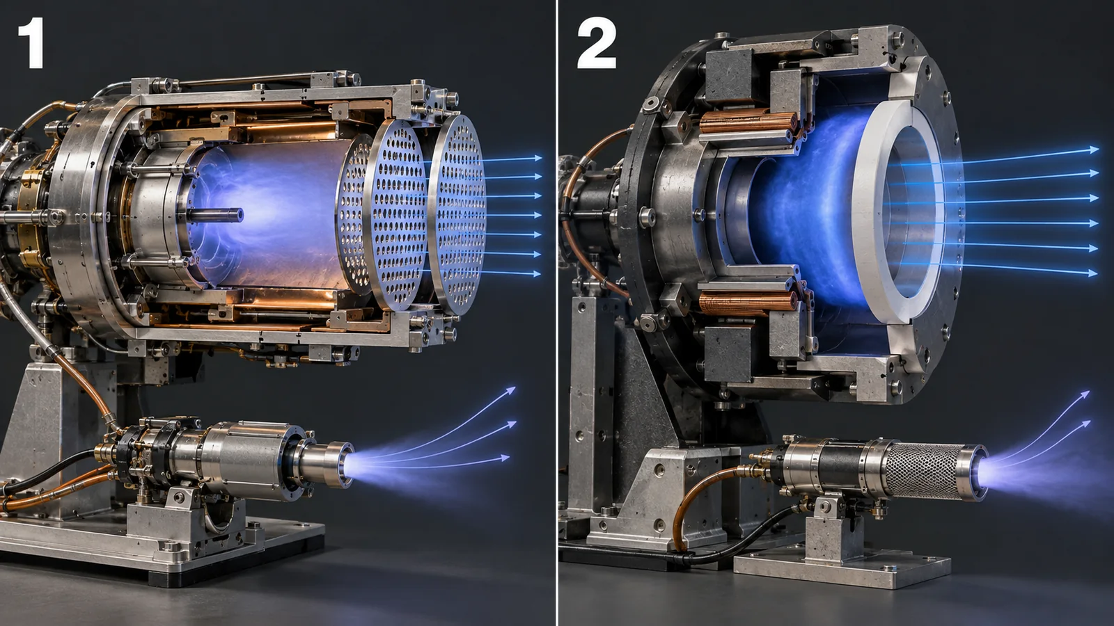
View original SVG, values and sources
Original SVG reference: Concept diagram (vector drawing). Simplified sections of a gridded ion thruster (left) and a Hall thruster (right), and where materials matter. Part names and cautions are from NASA's report [Ref. 1]. The cathode material is from NASA Glenn's inspection report [Ref. 10], and carbon-based grids from NASA's report [Ref. 11].
The grids hold a gap while ions wear them down
NASA's report says the gap between the grids is typically under 1 mm; this narrow gap is what gives the strong field and thrust. The price is that a foreign particle bridging the gap shorts the grids. Charge-exchange ions (ions that picked up an electron on the way and changed character), formed between and behind the grids, strike the grids and slowly erode them. Over time this leads to structural failure of a grid, electrons streaming back, or shorting from deposited conductive material Sourced[Ref. 1].
The spare flight thruster of NASA's Deep Space 1 went through a 30,352-hour extended life test (begun in October 1998 and voluntarily ended on 26 June 2003) Sourced[Ref. 6]. The post-test analysis reported the following Sourced[Ref. 7].
- Enlarged accelerator-grid holes and a narrower grid gap meant that at 26,000 hours the thruster could no longer prevent electron backstreaming at full power
- Pits eroded through the web of the accelerator grid, and grooves reached 45 % of the grid thickness near the center
- Material sputtered from the accelerator grid adhered to the downstream face of the screen grid, but did not spall off as flakes
The long-duration test of NASA Glenn's next-generation thruster NEXT ran from June 2005 to February 2014, reaching 51,184 hours, 918 kg of xenon and a total impulse of 35.5 MN·s before being ended voluntarily Sourced[Ref. 8]. The post-test inspection measured the grid wear in detail Sourced[Ref. 9].
The main points of the NEXT inspection are these Sourced[Ref. 9].
- The change in grid gap was −4 % at the center and −7 % on average. Comparing with −30 % in the NSTAR test, the presentation says the efforts to stabilize the NEXT grid gap were largely successful
- The accelerator grid lost 29.5 g by measurement; correcting for 12.4 g of deposits, mass lost to erosion is estimated at about 42 g (33.7 g in the NSTAR test). The minimum thickness of the screen grid was 86 % of its pre-test value
- Deposits of eroded material and of carbon were found. The carbon is estimated to have arrived by back-sputtering. Deposits reduced the screen-grid hole diameters by 2.2 % on average
- The downstream diameters of the accelerator-grid holes grew by 24 to 33 % (deposits excluded), and the minimum hole diameter by about 5 to 7 %
It has few moving parts (bearings or valves), but the ions themselves erode materials, so there is wear. Long-duration tests always measure grid erosion and deposition. Also, the cause of a ring-shaped deposit on the screen grid is unknown, but the presentation says a test-facility effect is likely, so ground testing can change the result Sourced[Ref. 9].
Carbon-based grids as an alternative
Molybdenum is the conventional grid material, and NASA papers compare carbon-based materials against it Sourced[Ref. 11]. NASA Glenn's report says carbon-based materials have shown nearly an order of magnitude better resistance to sputter erosion than molybdenum. Carbon/carbon composites (carbon fiber in a carbon matrix) and pyrolytic carbon grids have been tried in several programs Sourced[Ref. 11]. A NASA JPL report says 30 cm carbon-carbon grids passed vibration testing undamaged, while also noting that grids of 15 cm and larger have run into many problems, including passing vibration tests Sourced[Ref. 12].
A grid is a thin perforated plate, mounted as a pair facing each other across a gap under 1 mm, which must hold that gap through thermal expansion and launch vibration. Carbon-based materials erode less, but their mechanical robustness and vibration resistance as thin, large plates have been reported as challenges. NASA's report also says estimating grid life needs validated thermal modeling and proto-flight-level vibration tests Sourced[Ref. 1]. Choosing a grid material means looking not only at sputter resistance but also at dimensional stability, vibration and control of manufacturing scatter (commentary).
6. Hall thrusters: channel walls and magnetic shielding
NASA's report calls the Hall thruster arguably the most successful electric propulsion by number of units flown. The Soviet Union first flew an SPT-60 in 1971, and over 300 more flew through 2018. The first non-Russian one was the French PPS-1350 on ESA's SMART-1 in 2003. From 2019, 120 Starlink and 6 OneWeb spacecraft each used Hall thrusters, accelerating the count sharply. The report says SpaceX had launched over 11,500 Starlink satellites by April 2026 Sourced[Ref. 1].
The principle: an electrode (anode) sits at the back of an annular discharge channel, with an axial electric field and a radial magnetic field applied. Because the fields cross, electrons circle and advance slowly, and they ionize the neutral propellant, such as xenon, by collision. The ions are accelerated by the electric field and leave backward. Electrons come from a cathode, which also neutralizes the beam. Although its specific impulse is lower than a gridded ion thruster's, a Hall thruster has a higher thrust-to-power ratio, a simple design and good efficiency, which makes it a balanced choice for many missions Sourced[Ref. 1].
The walls erode, and set the life
NASA's report says that the life of a classical Hall thruster is limited mainly by erosion of the discharge channel wall, and that of a magnetically shielded one mainly by erosion of the pole covers. It adds that performance can also change over life through erosion and contamination Sourced[Ref. 1]. The channel walls have been boron nitride (BN) ceramic Sourced[Ref. 13].
NASA JPL showed a magnetic shielding arrangement of the field near the wall that reduces plasma contact with the wall, greatly cuts erosion of the BN walls and extends life by orders of magnitude Sourced[Ref. 13]. Because the wall is now protected, it also became possible to replace the insulating wall with a conductor. In the 6 kW H6 thruster, replacing BN rings with graphite kept efficiency above 60 %, within 2 % of the BN baseline. The graphite walls ran much cooler, and the same report says a thruster without ceramic walls is simpler and cheaper to build to survive launch loads, and radiates more efficiently, which raises the power capability Sourced[Ref. 13].
A magnetically shielded wall did not become harder; it erodes less because the ions that reach it carry less energy. Where the analogy breaks down: it is less like a shield and more like turning the wind aside. Erosion remains elsewhere, on the poles. In a JPL simulation, the maximum computed erosion rate at the inner pole of H6 exceeds the measured rate of back-sputtered deposits by about 4.5 times, and explains only part of the surface roughening seen after a 150-hour wear test Sourced[Ref. 14].
NASA's report says a Hall thruster's core can exceed 400 °C and its cathode 1,000 °C. Most of the heat radiates directly from the surfaces, but some soaks back to the spacecraft through the mount, propellant lines and harness, and a survival heater may be needed Sourced[Ref. 1]. Whether the wall is a ceramic such as BN or a conductor such as graphite is a trade not only on erosion resistance but on emissivity, thermal conduction and strength against launch loads (commentary).
7. Cathodes and propellants: how materials are chosen
Hollow cathodes: porous tungsten impregnated with barium
Both gridded-ion and Hall thrusters need cathodes to emit electrons. NASA Glenn's inspection report on NEXT examines the cathode insert (the electron-emitting part) as a porous tungsten matrix with an impregnate whose main constituents are barium, oxygen, aluminum and calcium. Using electron microscopy and X-ray diffraction, it looked at impregnate distribution, the thickness of the etched region, and the shape and phase of the emission surface Sourced[Ref. 10]. One expected failure mode is "barium depletion of the insert", which leads to excessive cathode temperature or inability to ignite Sourced[Ref. 10]. In this inspection, the impregnate area fraction of unused inserts and of inserts from the long-duration test agreed within uncertainty, and no significant change in the microstructure of the tungsten matrix and impregnate was seen Sourced[Ref. 10].
NASA's report says cathode life is sensitive to propellant purity and to air and humidity exposure before launch, and that feed-system cleanliness, bake-out and high-purity propellant matter. Heaterless cathodes are also advancing, and JPL's MaSMi work included a 25,000-ignition-cycle heaterless-cathode demonstration Sourced[Ref. 1].
Propellants: what gets thrown out
The "fuel" of electric propulsion is also a materials-compatibility question. NASA's report arranges it as follows Sourced[Ref. 1].
- Xenon: the propellant Hall thrusters have mainly flown on; heavy molecules, low ionization energy, easy to handle
- Krypton and argon: Starlink uses krypton, and its second generation also argon. They are less efficient than xenon and harder to store, but much cheaper; at the scale of thousands of satellites, cost and supply are given as the reasons
- Iodine: three times the storage density of xenon, stored as a solid with low vapor pressure. But it is a strong oxidizer, and its long-term effect on thruster and spacecraft is largely unknown. Beihangkongshi-1, launched in November 2020, made the first on-orbit demonstration of iodine propulsion, with two 90-minute burns changing altitude by 700 m. LunaH-Map, which carried a BIT-3, ended when its propulsion system could not operate; the team concluded that a tank valve was stuck closed (the report does not say whether iodine was involved)
- Water: a propellant for electrothermal (resistojet) systems, used by devices from Bradford, Pale Blue and Aurora
- PTFE and metals: pulsed plasma thrusters ablate PTFE, vacuum-arc thrusters use metals such as molybdenum, and electrosprays use ionic liquids or indium and gallium
NASA's report says that for the newer low-toxicity chemical propellants no public, peer-reviewed database of compatible materials exists, and that system developers have difficulty getting data Sourced[Ref. 1]. That is about chemical propulsion, but for electric propulsion too the report says iodine is a strong oxidizer whose long-term effect on the thruster and spacecraft is largely unknown Sourced[Ref. 1]. Combinations of tank, valve, seal and line materials with propellants look like a place where the materials side could contribute a lot (commentary).
8. How long they have run: flight records and life tests
The most important question in judging electric propulsion is "how many hours, and with how much propellant". Here are examples with numbers from NASA sources.
- Dawn (flight): an ion propulsion system developed at NASA JPL. The 1,218 kg spacecraft launched in 2007 and visited Vesta and Ceres. As of June 2016 the propulsion system had run over 48,454 hours, used about 401 kg of xenon and changed speed by over 11.0 km/s, described as a record for an on-board propulsion system Sourced[Ref. 5]
- NEXT long-duration test (ground): 51,184 hours, 918 kg of xenon, 35.5 MN·s Sourced[Ref. 8]
- JPL's MaSMi (ground): a small magnetically shielded Hall thruster. A 7,205-hour wear test used over 100 kg of xenon for a total impulse of about 1.55 MN·s. NASA's table says the same test article is being run on to 8,187 hours and 1.73 MN·s Sourced[Ref. 1]
- BHT-600 (ground): a 7,000-hour test at NASA Glenn ended after 70 kg of xenon Sourced[Ref. 1]
- SPT-70 (ground): experiments have demonstrated a life of 3,100 hours, about 450 kN·s Sourced[Ref. 1]
- GOCE (flight): ESA's gravity satellite (1,000 kg), at an altitude of 220 to 260 km, used two gridded-ion thrusters (T5) to cancel air drag until the xenon ran out in October 2013 Sourced[Ref. 1]
- Hayabusa (flight): JAXA's spacecraft (510 kg, launched on 9 May 2003) made a powered Earth swing-by with its ion engines in May 2004. Demonstrating ion-engine performance was one of its objectives. The title of a paper shows that these were microwave-discharge ion engines Sourced[Ref. 18][Ref. 16][Ref. 17]. JAXA says Hayabusa2's extended mission will use the remaining ion-engine xenon, of which about half remains Sourced[Ref. 19]
- OneWeb (flight): 80 satellites with BHT-350 thrusters launched in December 2022 and January 2023, and as of August 2023 over 100 units were operating, all reported operational Sourced[Ref. 1]
There are also cases that did not go well. LunaH-Map's BIT-3 was inoperable and the mission ended in late 2023 Sourced[Ref. 1]. On UWE-4, three of the four thrusters showed anomalous behavior Sourced[Ref. 1].
Dawn's 48,454 hours is a total for the propulsion system and is not necessarily the life of one thruster. NEXT's 51,184 hours is a single ground-test thruster whose operating point was changed along the way (the first 13,042 hours at full power, then stretches of throttled operation, and finally full power again) Sourced[Ref. 9]. A thruster of a few tens of watts and one of several kilowatts deliver very different total impulse in the same "1,000 hours". Look at propellant mass (kg) and total impulse (N·s) as well as hours; that is how NASA's report reads them.
9. Effects on the spacecraft: heat and plume
A thruster runs hot right next to the spacecraft and ejects a plasma. The spacecraft's materials feel the effects of this "neighbor".
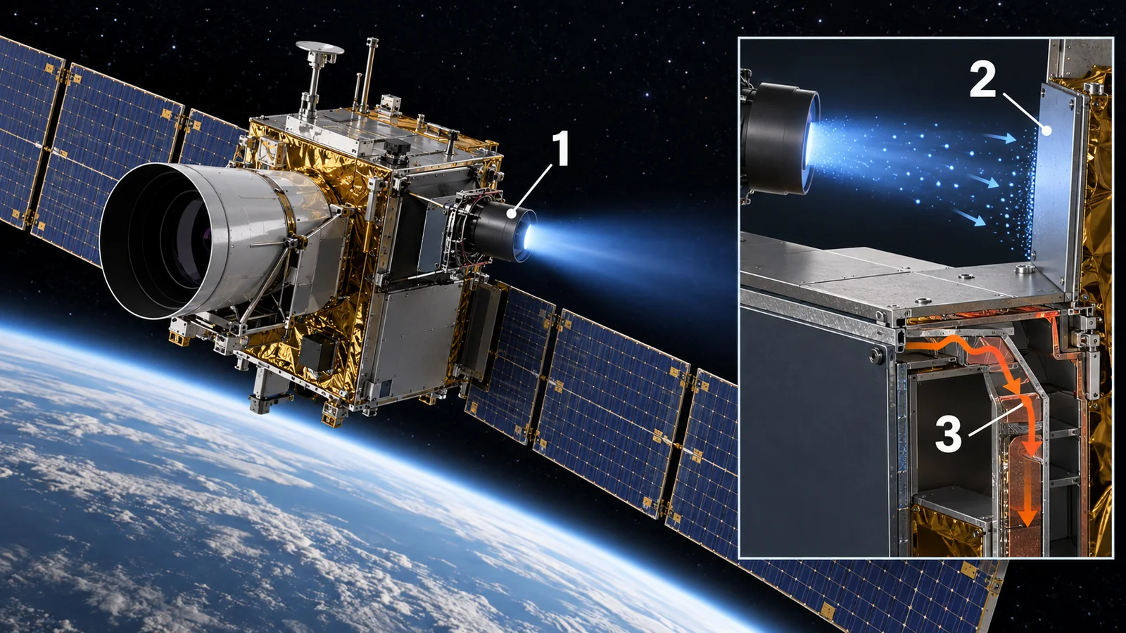
View original SVG, values and sources
Original SVG reference: Concept diagram (vector drawing). What a thruster does to its spacecraft. Heat soak-back and plume effects are from NASA's report [Ref. 1] and the abstract of the SPT-100 witness-plate test [Ref. 15].
- Heat: most of a Hall thruster's heat is radiated directly from its surfaces, but some soaks back to the spacecraft through the mount, lines and harness. Low-efficiency types such as ambipolar and pulsed thrusters carry a larger heat load Sourced[Ref. 1]. For the thermal design of the body see our explainer on spacecraft thermal control
- Plume (the exhaust plasma): plume ions of a Hall thruster erode or contaminate surfaces even at large angles. Ground measurements at large angles may under-predict what happens in flight Sourced[Ref. 1]
- A witness-plate example: NASA exposed witness plates to the plume of an SPT-100 for 50 hours. In the most energetic region there was a net removal of material from samples facing the thruster, and at the periphery net deposits were seen along with changes in optical properties. Samples inside collimators changed within experimental uncertainty Sourced[Ref. 15]
- Electrosprays: the propellant is conductive, and deposits can short circuits or foul solar panels. Plume shields are often used to protect surfaces Sourced[Ref. 1]
The SPT-100 test showed both sides: erosion in the strong region, deposition and changed optical properties at the edge Sourced[Ref. 15]. Solar-cell cover glass, radiator paint and optical thin films all have surface optical properties as their very function. As the thermal-control article shows, a rise of 0.05 in absorptance alone cuts a radiator's heat rejection substantially (our explainer on spacecraft thermal control). Materials near the plume need to be judged on sputter resistance and on changes in optical properties from deposits together (commentary).
10. Limits, and what could not be confirmed
- Scope of this article: it rests on NASA's report on small-spacecraft devices (spacecraft of 180 kg or less) and on NASA technical reports. We did not check primary sources on high-power Hall thrusters for large geostationary satellites, nuclear-electric propulsion or magnetoplasma propulsion, so we do not cover them
- Propellant price and supply: we do not use market estimates, so we give no price figure for xenon
- Sources checked by abstract only: many of the NTRS reports behind Figs. 6 to 8 were checked by abstract only (stated in the references). The NEXT inspection presentation and the insert report were checked in full text
- Hayabusa numbers: we could not confirm operating hours, propellant mass or performance figures for its ion engines from JAXA's official pages or the NASA abstract. We checked only the title and bibliographic data of the IEEE paper, not its text
- Grid materials: we do not state the grid material of any specific engine where the sources did not confirm it (molybdenum or carbon-based)
- Calculations: the propellant fractions, thrust-to-power ratios and days are illustrative values from simple formulas, not predictions for any real spacecraft
- The text of standards: we did not check the requirements in the text of the ECSS standards. We did not find a published ISO standard on electric propulsion within the range we checked
- ASTM: we did not open ASTM's site
11. How to read the yardsticks and standards
Electric propulsion is evaluated by combining "performance measured in a ground vacuum chamber", "flight record" and "inspection of material wear". The yardsticks are: (1) thrust, specific impulse and efficiency (at nominal operating conditions); (2) total impulse and propellant throughput (kg); (3) operating hours in life tests and the wear measured afterward; (4) repeated cycles such as ignition counts; (5) the effect of the plume on other surfaces; and (6) development maturity. All of them depend on the conditions of the test facility.
| What is evaluated | Typical test or method (name, source) | Standards and guidance (ECSS, ISO, NASA and others) | Cautions in reading |
|---|---|---|---|
| Thrust, specific impulse, efficiency | Values at the nominal operating condition are given. Where a manufacturer states no nominal condition, NASA's table says it either asked or assumed one from similar devices Sourced[Ref. 1] | Engineering requirements for propulsion systems including electric: ECSS-E-ST-35C Rev.1 "Propulsion general requirements" [Ref. 20], ECSS-E-ST-35-01C "Liquid and electric propulsion for spacecraft" [Ref. 21] | Check which condition a value is for. For Hall thrusters, facility effects (such as pumping capacity) can make ground and flight differ [Ref. 1]. We did not check the standards' text |
| Life and total impulse | Long-duration test: record operating hours, propellant throughput and total impulse, and validate a life model (the NEXT example) Sourced[Ref. 8] | As above (ECSS-E-ST-35-01C includes verification requirements). The parts that set test durations and conditions were not checked in the text | Read propellant mass and total impulse. Ground and flight mean different things |
| Wear and erosion | Post-test inspection: grid thickness, hole diameters, groove depths, mass, cross-sections (the NEXT example) Sourced[Ref. 9]. Electron-microscope examination of inserts Sourced[Ref. 10] | We could not confirm a common standard | Deposits such as back-sputtered carbon can contaminate the measurement (Chapter 5) |
| Plume effects | Expose witness plates to the plume in a facility and measure surface analysis and optical changes (the SPT-100 example) Sourced[Ref. 15] | We could not confirm a common standard | Measurements at large angles can read low [Ref. 1]. Not identical to flight conditions |
| Maturity | NASA's report does not use TRL directly but classifies devices by evidence of progress toward mission infusion (PMI status), and refers to the 2022 JANNAF TRL guidelines Sourced[Ref. 1] | — | The same device can have a different maturity for a low-orbit small satellite and for a deep-space probe, the report says |
| Standardization activity | A document under development in ISO/TC 20/SC 14: ISO/DTR 26097 "Space systems — Micro-cathode arc propulsion module for CubeSats" Sourced[Ref. 22] | Status "under development" (stage 50.00, final-text approval stage). Not a published standard | A draft cannot be used as a requirement. We did not check its contents |
The arrangement of this table is Our calculation (our own reordering). Standard numbers, titles and status were checked on the official pages of ECSS and ISO (checked 17 October 2026). ISO texts are paywalled, so we limited ourselves to titles and scope. We did not open ASTM's site.
Cautions in reading (for materials engineers)
- "Nominal" is not "full range": NASA's table lists values only at each device's nominal operating condition, and asks readers to follow the references for the full range
- Ground tests and flight are different things: facility back-pressure and the angle of plume measurements can make ground values differ from flight
- Some numbers are unverified: NASA's table carries a note not to assume data has been independently verified unless otherwise published
- Check whether a standard is published: something under development, like ISO/DTR 26097, cannot be used as a requirement
12. Glossary
- Thrust
- The force from the reaction of ejecting propellant. For electric propulsion, in millinewtons (mN).
- Specific impulse (Isp)
- A measure of how well propellant is used (fuel economy). Unit: seconds. Exhaust speed divided by g0.
- Total impulse
- Thrust multiplied by firing time (N·s): the total momentum a device can deliver.
- Delta-v (Δv)
- The change in speed a propulsion system can deliver. A measure of how much orbit-changing work it can do.
- Ideal rocket equation
- The formula linking velocity change and propellant fraction.
- Plasma
- A gas whose atoms have split into electrons and ions and conducts electricity.
- Grids (ion optics)
- The two perforated electrodes that extract and accelerate the ions.
- Neutralizer
- A cathode that emits electrons to keep the beam charge-neutral.
- Charge-exchange ion
- An ion that picked up an electron in the beam and stays slow. A cause of grid erosion.
- Electron backstreaming
- Electrons slipping past the negative voltage of the accelerator grid back into the discharge chamber.
- Hall thruster
- A thruster that makes plasma with electric and magnetic fields and accelerates the ions.
- Magnetic shielding
- A design that shapes the magnetic field near the wall so that less plasma reaches it, reducing erosion.
- BN (boron nitride)
- The ceramic traditionally used for channel walls.
- Hollow cathode
- A tubular cathode that emits electrons. An impregnated insert emits them.
- Insert
- The electron-emitting part inside a hollow cathode: porous tungsten impregnated with barium compounds.
- PPU
- Power processing unit: converts spacecraft power into the voltages and currents a thruster needs.
- PPT, VAT
- Pulsed plasma thruster, vacuum arc thruster: use solid propellant ablated by an arc between electrodes.
- Plume
- The spread of exhaust plasma leaving a thruster.
- Thermal soak-back
- Heat from the thruster flowing into the spacecraft through mount, lines and harness.
- ECSS
- European Cooperation for Space Standardization. Europe's cooperative body for space standards.
13. References
- NASA (Small Spacecraft Systems Virtual Institute) "State-of-the-Art of Small Spacecraft Technology", Chapter 4 In-Space Propulsion (2026 edition, including Tables 4-1, 4-9, 4-10 and 4-11; checked 17 October 2026) — nasa.gov/smallsat-institute/sst-soa/in-space-propulsion/
- NASA Glenn Research Center "Specific Impulse" (definitions of thrust, total impulse and specific impulse Isp = Veq/g0; checked 17 October 2026) — grc.nasa.gov/www/k-12/airplane/specimp.html
- NASA Glenn Research Center "Ideal Rocket Equation" (checked 17 October 2026) — www1.grc.nasa.gov/beginners-guide-to-aeronautics/ideal-rocket-equation/
- NIST "standard acceleration of gravity" (9.806 65 m/s2, exact; CODATA 2022; checked 17 October 2026) — physics.nist.gov/cgi-bin/cuu/Value?gn
- Garner C. E., Rayman M. D. (NASA JPL) "In-flight Operation of the Dawn Ion Propulsion System Through the Low Altitude Mapping Orbit at Ceres" (2016; abstract only) — ntrs.nasa.gov/citations/20190025608
- Sengupta A., Brophy J. R., Goodfellow K. D. (NASA JPL) "Status of the extended life test of the Deep Space 1 flight spare ion engine after 30,352 hours of operation" (abstract only) — ntrs.nasa.gov/citations/20060043359
- Anderson J. R., Sengupta A., Brophy J. R. (NASA JPL) "Post-Test Analysis of the Deep Space One Spare Flight Thruster Ion Optics" (abstract only) — ntrs.nasa.gov/citations/20110013157
- Shastry R., Herman D. A., Soulas G. C., Patterson M. J. (NASA Glenn) "End-of-Test Performance and Wear Characterization of NASA's Evolutionary Xenon Thruster (NEXT) Long-Duration Test" (2014; abstract only) — ntrs.nasa.gov/citations/20140016766
- Soulas G. C., Shastry R. (NASA Glenn) "Post-Test Inspection of NASA's Evolutionary Xenon Thruster Long Duration Test Hardware: Ion Optics" (presentation of 25 July 2016; full text checked) — ntrs.nasa.gov/citations/20170002704
- Mackey J., Shastry R., Soulas G. (NASA Glenn) "Characterization of the NEXT Hollow Cathode Inserts After Long-Duration Testing" (text checked) — ntrs.nasa.gov/citations/20170009085
- Haag T., Patterson M., Rawlin V., Soulas G. (NASA Glenn) "Carbon-Based Ion Optics Development at NASA GRC" (2002; abstract only) — ntrs.nasa.gov/citations/20020061976
- Snyder J. S., Brophy J. R. (NASA JPL) "Performance Characterization and Vibration Testing of 30-cm Carbon-Carbon Ion Optics" (abstract only) — ntrs.nasa.gov/citations/20070022514
- Goebel D. M., Hofer R. R., Mikellides I. G., Katz I., Polk J. E., Dotson B. (NASA JPL) "Conducting Wall Hall Thrusters" (2013; abstract only) — ntrs.nasa.gov/citations/20150007838
- Mikellides I. G., Ortega A. L. (NASA JPL) "Assessment of Pole Erosion in a Magnetically Shielded Hall Thruster" (2014; abstract only) — ntrs.nasa.gov/citations/20160008257
- Pencil E. J. (NASA Lewis) "Preliminary far-field plume sputtering characterization of the Stationary Plasma Thruster (SPT-100)" (abstract only) — ntrs.nasa.gov/citations/19940020293
- Abell P. A. (NASA) "The Hayabusa Spacecraft Sample Return Mission" (abstract only; launched 9 May 2003; demonstrating ion-engine performance was one objective) — ntrs.nasa.gov/citations/20100033487
- Kuninaka H., Nishiyama K., Funaki I., Shimizu Y., Yamada T., Kawaguchi J. "Assessment of Plasma Interactions and Flight Status of the HAYABUSA Asteroid Explorer Propelled by Microwave Discharge Ion Engines", IEEE Transactions on Plasma Science, 34(5), 2125-2132 (2006; title and bibliographic data only; text not checked) — doi.org/10.1109/TPS.2006.876513
- JAXA Institute of Space and Astronautical Science (ISAS) "HAYABUSA" (mass 510 kg, launched on M-V-5, powered Earth swing-by with ion engines in May 2004; checked 17 October 2026) — isas.jaxa.jp/en/missions/spacecraft/past/hayabusa.html
- JAXA Institute of Space and Astronautical Science (ISAS) "Hayabusa2" (the extended mission uses the remaining ion-engine xenon, about half; checked 17 October 2026) — isas.jaxa.jp/en/missions/spacecraft/current/hayabusa2.html
- ECSS ECSS-E-ST-35C Rev.1 "Propulsion general requirements" (6 March 2009; checked 17 October 2026) — ecss.nl/standard/ecss-e-st-35c-rev-1-propulsion-general-requirements/
- ECSS ECSS-E-ST-35-01C "Liquid and electric propulsion for spacecraft" (15 November 2008; checked 17 October 2026) — ecss.nl/standard/ecss-e-st-35-01c-liquid-and-electric-propulsion-for-spacecraft/
- ISO ISO/DTR 26097 "Space systems — Micro-cathode arc propulsion module for CubeSats" (draft technical report; status "under development", stage 50.00; checked 17 October 2026) — iso.org/standard/92605.html
14. Claim-to-source audit
| Claim in the text | Basis | Class |
|---|---|---|
| The classification of electric propulsion (electrothermal, electrostatic, electromagnetic), thrust-to-power generally below 75 mN/kW, 38 mN at 500 W, hundreds to thousands of hours, the descriptions and cautions for each type, the thrust and specific-impulse ranges of Table 4-1, the nominal values of Hall thrusters in Table 4-10, the history of Hall thrusters (SPT-60, SMART-1, Starlink, OneWeb), core above 400 °C and cathode above 1,000 °C, heat soak-back, plume effects, propellants (xenon, krypton, argon, iodine, water, PTFE), GOCE, MaSMi, BHT-600, SPT-70 and OneWeb records, the LunaH-Map and UWE-4 problems, heaterless cathodes, the TRL classification | NASA's report, Chapter 4 Reference 1 https://www.nasa.gov/smallsat-institute/sst-soa/in-space-propulsion/ | Sourced |
| The definitions of thrust and specific impulse, the ideal rocket equation, and the value of g0 | Two NASA Glenn pages, NIST Reference 2 https://www.grc.nasa.gov/www/k-12/airplane/specimp.html Reference 3 https://www1.grc.nasa.gov/beginners-guide-to-aeronautics/ideal-rocket-equation/ Reference 4 https://physics.nist.gov/cgi-bin/cuu/Value?gn | Sourced |
| The cumulative operation of Dawn's propulsion system (48,454 hours, about 401 kg, over 11.0 km/s) | Garner and Rayman (abstract only) Reference 5 https://ntrs.nasa.gov/citations/20190025608 | Sourced |
| The DS1 spare-engine test (30,352 hours, ended 26 June 2003) and grid wear (backstreaming at 26,000 hours, grooves 45 % of thickness) | Sengupta et al., Anderson et al. (both abstract only) Reference 6 https://ntrs.nasa.gov/citations/20060043359 Reference 7 https://ntrs.nasa.gov/citations/20110013157 | Sourced |
| The NEXT long-duration test (51,184 hours, 918 kg, 35.5 MN·s) and the grid gap, hole diameter, mass and deposition figures | Shastry et al. (abstract only), Soulas and Shastry (full presentation) Reference 8 https://ntrs.nasa.gov/citations/20140016766 Reference 9 https://ntrs.nasa.gov/citations/20170002704 | Sourced |
| The composition of the cathode insert (porous tungsten with barium and other impregnates), the barium-depletion failure mode, the comparison with unused parts | Mackey et al. (full text) Reference 10 https://ntrs.nasa.gov/citations/20170009085 | Sourced |
| The sputter resistance of carbon-based grids (about an order of magnitude better than molybdenum) and the vibration results and challenges | Haag et al., Snyder and Brophy (both abstract only) Reference 11 https://ntrs.nasa.gov/citations/20020061976 Reference 12 https://ntrs.nasa.gov/citations/20070022514 | Sourced |
| The reduction of BN wall erosion by magnetic shielding, the result of replacing it with graphite walls (efficiency above 60 %, within 2 %), and the pole-erosion calculation | Goebel et al., Mikellides and Ortega (both abstract only) Reference 13 https://ntrs.nasa.gov/citations/20150007838 Reference 14 https://ntrs.nasa.gov/citations/20160008257 | Sourced |
| The SPT-100 plume witness-plate results (50 hours) | Pencil (abstract only) Reference 15 https://ntrs.nasa.gov/citations/19940020293 | Sourced |
| Hayabusa's mass, launch and ion-engine swing-by, the "microwave discharge" in the paper title, and Hayabusa2's extended mission and remaining xenon | Two ISAS pages, NASA (abstract only), Kuninaka et al. (title and bibliographic data only) Reference 18 https://www.isas.jaxa.jp/en/missions/spacecraft/past/hayabusa.html Reference 19 https://www.isas.jaxa.jp/en/missions/spacecraft/current/hayabusa2.html Reference 16 https://ntrs.nasa.gov/citations/20100033487 Reference 17 https://doi.org/10.1109/TPS.2006.876513 | Sourced |
| The titles and scope of ECSS-E-ST-35C Rev.1 and ECSS-E-ST-35-01C, and the title and status of ISO/DTR 26097 | ECSS and ISO official pages Reference 20 https://ecss.nl/standard/ecss-e-st-35c-rev-1-propulsion-general-requirements/ Reference 21 https://ecss.nl/standard/ecss-e-st-35-01c-liquid-and-electric-propulsion-for-spacecraft/ Reference 22 https://www.iso.org/standard/92605.html | Sourced |
| The propellant fractions in Fig. 2 (64, 18, 10 %, 87, 33, 18 %), the thrust-to-power ratios and efficiencies in Fig. 3 (45 to 66 mN/kW, 0.27 to 0.52, BIT-3 at 14 mN/kW), and the 500 kg example (thrust about 68 mN, about 231 days, about 92 kg of propellant) | Our calculation (assumptions in the text). Not values of a real spacecraft | Our calculation |
| Readings such as "swapping a temperature limit for an erosion limit", "power turns into a solar-cell and heat problem", "a grid must resist both erosion and breakage", "wall materials are chosen for heat shedding too" and "the plume both erodes and fouls" | This article's organization and commentary based on published content. Not views stated by any of the organizations | Commentary |
| High-power Hall thrusters, nuclear-electric propulsion, propellant prices, the grid material of each engine, numbers for Hayabusa's ion engines, and the text of the standards | Not confirmed within the range of primary sources this article could reach, so not stated | Commentary |
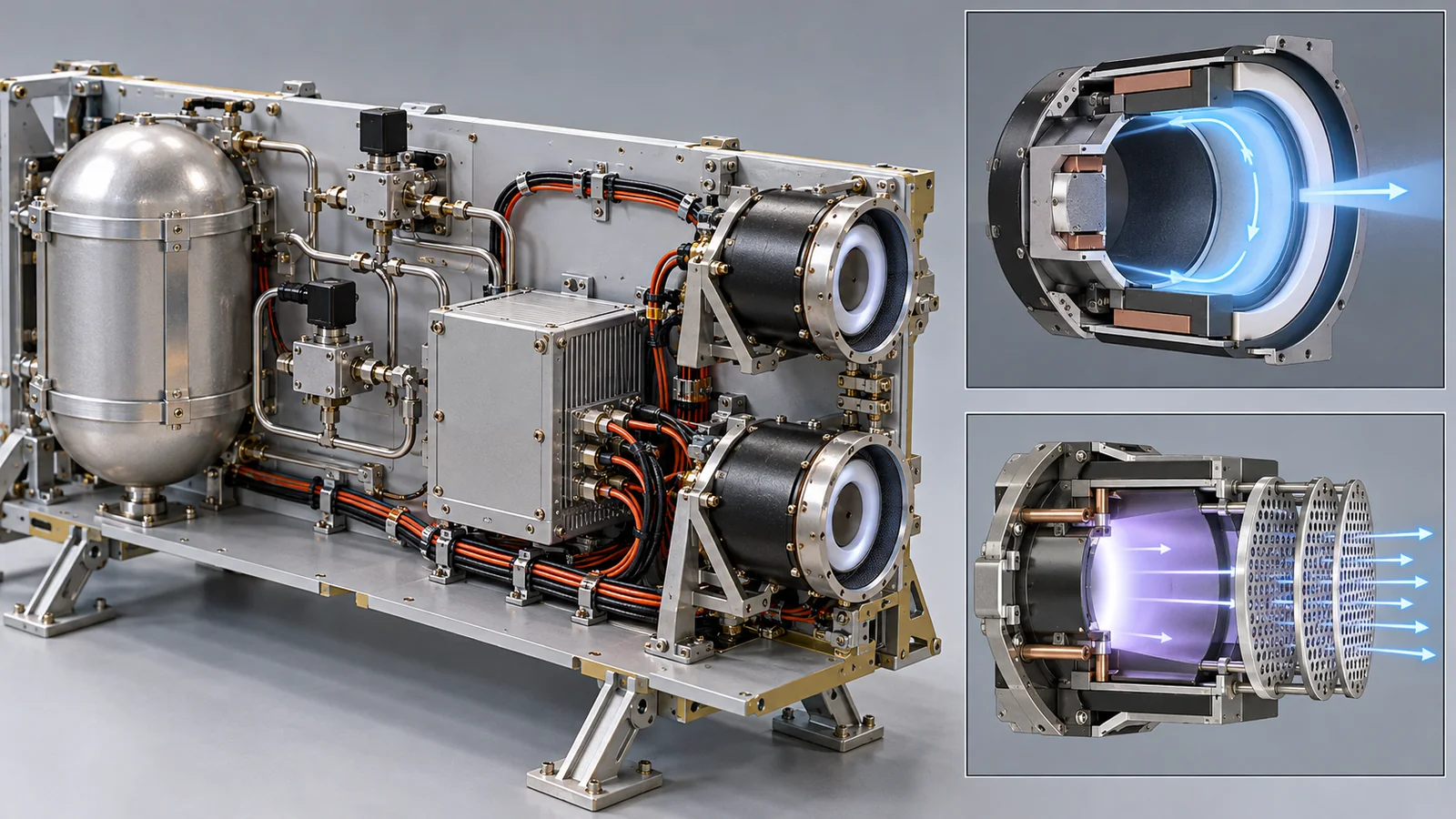
| That, of Figs. 1 to 9, Figs. 1 and 9 (AI image frames) are illustrative concept images, and that the other figures are drawings for explanation, not observations of real data | A note by this article | Commentary |
Last updated: 17 October 2026 / Sources are limited to primary materials (NASA's report on small-spacecraft technology, NASA technical reports, NASA Glenn, NIST, JAXA, the official pages of ECSS and ISO, and bibliographic data of peer-reviewed papers). The propellant fractions, thrust-to-power ratios and days are illustrative calculations made for this article and do not predict any real spacecraft. We could not confirm high-power Hall thrusters, propellant prices, the grid material of each engine, numbers for Hayabusa's ion engines, or the requirements in the standards' texts, so we do not state them.