TECHNOLOGY EXPLAINER
Super Engineering Plastics for Space
— What PEEK-class plastics are good and bad at in light structures, insulation and wiring
Replace metal with a light plastic, and do it in the vacuum, temperature swings and radiation of space. Super engineering plastics, of which PEEK is the best known, are strong candidates. In space, though, they are judged by yardsticks that do not appear in a ground-side catalog. Written for materials engineers who know little about spaceflight, this article separates the strengths, very little outgassing and a flight record, from the weaknesses: erosion by oxygen atoms at about Kapton's rate, a sharp loss of stiffness above the glass transition (about 143 °C) and poor heat conduction. It does so with numbers from primary sources. The later chapters also sort out how far 3D-printed PEEK has been checked against space criteria.
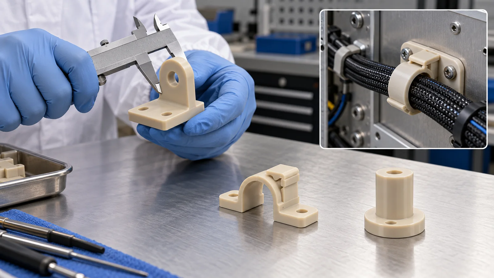
- The short version / what to know first / where this fits in the series
- Background: super engineering plastics and the "five enemies" of space
- Where they are used in space
- As a structural material: the orbital record of carbon fiber and PEEK
- Enemy 1, vacuum: outgassing varies greatly by material
- Enemy 4, atomic oxygen: PEEK erodes about as fast as Kapton
- Enemy 2, UV and radiation: molecular structure and test atmosphere decide
- Enemy 3, temperature: the glass-transition wall and heat paths
- 3D-printed PEEK
- Limits, and what could not be confirmed
- How to read the yardsticks and standards
- Glossary / References / Claim-to-source audit
Sourced = stated in published material (link given)
Our calculation = a value this article worked out from stated assumptions
Not yet confirmed = plans, drafts or targets that are not settled
Readings for the materials field are marked as commentary. Inference is shown in bold. Every analogy comes with its limit.
Outgassing numbers are records from the NASA Goddard database and values from a paper reporting ESA tests. Sample shape, pre-treatment and laboratory differ from record to record, so we do not rank the records. In-orbit measurements are values under the conditions in the paper or report (orbit, duration, orientation). The temperature results from analysis come from a calculation for one assumed CubeSat design, not a measurement on hardware. Manufacturer values are labeled as the manufacturer's, and for standards we only checked titles, scope and status. Because this field changes fast, standards carry a checking date (17 October 2026).
1. The short version / what to know first / where this fits in the series
- Where they fit: light structures, insulation, wiring and sliding parts. Carbon-fiber-reinforced PEEK was reported to show no change in its thermal expansion over about four months in an in-orbit experiment on Ten-Koh, a small satellite from the Kyushu Institute of Technology. The NASA database holds records with applications as sensor frames, insulating isolators and cable tubing Sourced[Ref. 3, 14]
- The strength is "little gas"; the weaknesses are "erodes, softens and traps heat". PEEK's outgassing is small in most NASA records, and even 3D-printed PEEK gave an RML of 0.11 % in an ESA test. On the other hand, its atomic-oxygen erosion yield is 2.99 for PEEK and 3.00 for Kapton H (× 10-24 cm3 per atom), about the same. It loses stiffness above its glass transition (about 143 °C), and because its thermal conductivity is low, an analysis reports local temperatures approaching that point Sourced[Ref. 1, 4]
- 3D printing offers freedom, but we could not confirm a flight record. Printed parts lose density and elongation to pores. The tests outside the ISS were done on printed PEI (Ultem) and PEKK; printed PEEK is at the ground-test stage Sourced[Ref. 4, 5, 6]
PEEK's crystallinity, glass transition versus melting point, how fillers (glass fiber, carbon fiber) work and processing conditions are covered in our explainer on PEEK and super engineering plastics (in the polymers and resins field), and we do not repeat them. Space terms (outgassing, atomic oxygen, erosion yield and so on) are also treated in our explainer on polyimides for space, but this article can be read on its own, since each term is explained where it appears.
Reading our explainers on the space environment and on polyimides for space first gives the five enemies and the ideas of outgassing and erosion yield. Combining plastics with carbon fiber is covered in our explainer on CFRP and composites for space, additive manufacturing in general in our explainer on additive manufacturing for space, and heat-dissipation design in our explainer on spacecraft thermal control.
2. Background: super engineering plastics and the "five enemies" of space
"Super engineering plastic" is a name for resins with higher heat resistance, strength and chemical resistance than general engineering plastics such as polyamide or polycarbonate. No law or standard defines it. This article centers on PEEK (polyetheretherketone) and covers PEI (polyetherimide, trade name Ultem), PPS (polyphenylene sulfide), PSU and PES (polysulfone types), LCP (liquid crystal polymer) and PAI (polyamide-imide, trade name Torlon), with polyimide and PBI (polybenzimidazole) alongside for comparison.
Here are PEEK's basic numbers, as given in the datasheet values a paper cited: glass transition temperature 143 °C, melting point 343 °C, thermal conductivity 0.25 W/m·K, density 1.30 g/cm3, tensile modulus 4 GPa Sourced[Ref. 4].
The polymer chains in a plastic cannot move when it is cold (a hard, glassy state). Above Tg the more mobile segments of the chains start to move and the material suddenly softens (a rubbery state). The melting point is, for a crystalline plastic such as PEEK, the temperature at which the crystals melt and the shape is lost. Above its Tg (about 143 °C) PEEK keeps its shape because the crystals remain as a skeleton, but its stiffness drops sharply. In the Victrex values given in our explainer on PEEK and super engineering plastics, flexural stress falls from 165 MPa at 23 °C to 19 MPa at 175 °C. Where the analogy breaks down: butter going from "a little soft" (near Tg) to "fully melted" (melting point) is similar, but butter has no crystalline skeleton in this sense.
This series organizes the space environment as five enemies. A satellite in orbit is in a state of "falling while moving sideways fast enough never to hit the ground", and low orbit near 400 km still holds a thin atmosphere with oxygen atoms. How super engineering plastics fare against the five enemies is shown below (the orbit story is told in more detail in Chapter 2 of our explainer on polyimides for space).
High heat resistance and little outgassing are real strengths. But they are not enough. On a surface facing forward in low orbit, PEEK erodes as fast as Kapton. A temperature above the glass transition can appear in a very small spot, depending on how heat paths are designed. And ultraviolet and radiation test results change with the kind of material and the test atmosphere. The word "super" does not mean a pass in space.
3. Where they are used in space
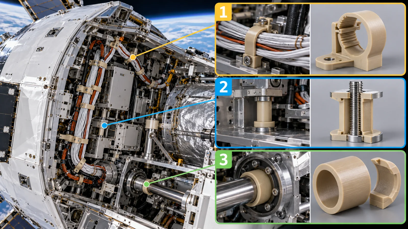
The uses we could confirm from primary sources are summarized in the figure and table below.
View original SVG, values and sources
Original SVG reference: Concept diagram (vector drawing). Where PEEK-class plastics are used inside a spacecraft, and the evidence we could confirm. The layout is illustrative and does not show any specific satellite. Item 5 (3D printing) is at the ground-test stage.
| No. | Use | What the primary sources confirm | Enemy covered here |
|---|---|---|---|
| 1 | Structural panels (carbon fiber and PEEK) | The Ten-Koh paper says CF/PEEK was the main material of the external structure of Shinen-2, a deep-space probe of the Kyushu Institute of Technology, and that it "survived the launch and space environment" (a statement about an earlier project). On Ten-Koh, three CF/PEEK samples were used to measure thermal expansion in orbit Sourced[Ref. 3] | Temperature (Chapter 8), outgassing |
| 2 | Sensor frames and insulating spacers | The NASA database has records for PEEK with the application "magnetometer sensor frame" (Victrex 450G903 black, 2010, record GSFC32026), and "isolator" for a PEEK sheet (2012, GSFC33550) and a 30 % glass-filled bar (2012, GSFC33412) Sourced[Ref. 14] | Outgassing (Chapter 5) |
| 3 | Cable tubing and heat-shrink tubing | The NASA database has records for PEEK tubing with the application "cable insulation" (2012, GSFC33343 and 33415) and for PEEK "shrink tubing" (2006 and 2010) Sourced[Ref. 14] | Outgassing, AO |
| 4 | Sliding parts and seals | The NASA database has a record for black PEEK with dry-film lubricant, application "ring seal" (1991, GSFC19615). A presentation from BAM (Germany's Federal Institute for Materials Research and Testing) says in its abstract that MoS2-filled PEEK/PTFE composites reach a friction coefficient of about 0.03 in high vacuum Sourced[Ref. 14, 11] | Outgassing |
| 5 | 3D-printed housings and structures | A "proof-of-concept model" of a 2U CubeSat structure printed in PEEK (Rinaldi et al.) and an electrostatic analyzer printed in CNT-filled PEEK (Larrick et al.) were tested on the ground. We could not confirm a flight record within the sources we checked Sourced[Ref. 4, 5] | General (Chapter 9) |
The "enemy covered" column is this article's organization of what the sources say (commentary). The "application" field in the NASA database is the description written by whoever requested the test, not a guarantee that the material flew or may be used (our reading). We did not check how much is used on spacecraft.
4. As a structural material: the orbital record of carbon fiber and PEEK
Among super engineering plastics, the best-documented space record is the in-orbit measurement of thermal expansion of carbon-fiber-reinforced PEEK (CF/PEEK).
Ten-Koh, a small satellite of the Kyushu Institute of Technology, was launched on 29 October 2018 and orbits in a sun-synchronous orbit at about 600 km. It carried a "material mission" with three CF/PEEK samples (50 mm long, 10 mm wide, 2 mm thick) and measured their coefficient of thermal expansion (CTE) in orbit using strain gauges. The samples were made of plain-woven carbon fabric from Toray and PEEK from Victrex, and two of the three had a protective coating (one for ultraviolet light, one for atomic oxygen) Sourced[Ref. 3].
| Item | What the paper states |
|---|---|
| Observation period | 9 November 2018 to 19 March 2019, 101 measurements in all. Contact with the ground station was lost on 19 March 2019 and there are no later data (the authors say a single-event effect from radiation was the likely cause) |
| Sample temperature | About -40 to 20 °C each orbit. Sensors on nearby solar panels read an upper limit of 50 °C and a lower limit of -45 °C |
| Result | CTE varied non-linearly with temperature, and no shift in CTE was seen over about four months (120 days). The trend agreed with ground tests (median of thermomechanical analysis 3.11 ppm/°C) and with earlier in-orbit data |
| Measurement design | Each strain gauge was fixed by thermal welding (up to 400 °C) between two CF/PEEK pieces. Adhesive would outgas in vacuum and the gauge could detach and become debris, so it was avoided. Destructive (tensile) tests were also skipped so as not to create debris |
All Sourced (Abdullah et al., Aerospace 2020 [Ref. 3]). The in-orbit CTE values differ between samples because of strain-gauge misalignment; the authors attribute the differences between orbit and ground data to that misalignment and to different heating and cooling rates.
The paper gives as reasons for CF/PEEK's performance that the toughness of the PEEK resin suppresses the microcracks that thermal cycling causes, and that in a thermoplastic composite internal stress is dissipated inside the material and so is less likely to become a crack (the authors' explanation). What is more interesting from the materials side is that a thermoplastic melts, so parts can be welded without adhesive. This experiment used exactly that property to embed the strain gauges without an outgassing adhesive. Not having to bring in a separate "adhesive layer", as a thermoset would require, is an advantage in vacuum (commentary).
5. Enemy 1, vacuum: outgassing varies greatly by material
The outgassing test (measuring mass loss and condensation in vacuum) and the meaning of TML, RML, WVR and CVCM are explained in detail in Chapter 4 of our explainer on polyimides for space. A quick recap: TML is the total mass lost, WVR is the water regained, RML = TML − WVR is the loss excluding water, and CVCM is what condensed on a cold plate. ECSS-Q-ST-70-02C runs the test in vacuum (10-3 Pa or lower) at 125 °C for 24 hours, and sets minimum screening values for material selection of RML < 1.0 % and CVCM < 0.10 % Sourced[Ref. 13].
Three points in reading the figure.
- PEEK, PPS and LCP often show little gas. The PEEK molding compound has a TML of 0.26 % (RML 0.14 % without water), PPS 0.05 % and LCP 0.03 %. Rinaldi and colleagues say the high crystallinity of PEEK is what to expect behind its low outgassing Sourced[Ref. 14, 4].
- PAI, polyimide, PBI and PES have records with large TML. ECSS says the TML of water-absorbing materials (polyamides, polyimides, polyurethanes and so on) is often above 1.0 % Sourced[Ref. 13]. In the figure, Vespel SP-1 (polyimide) has a TML of 1.04 % but an RML of 0.85 %, while Torlon 4203 (PAI) has a TML of 1.68 % and, even without water, an RML of 1.36 %, over the limit. Yet another Torlon, 5030 (a different grade), has a TML of 0.42 % and an RML of 0.20 %, so values differ greatly by grade Sourced[Ref. 14].
- Even the same product gives different values in different records. Miniflex PEEK tubing has two records. One has a TML of 0.71 % and a CVCM of 0.12 % (above the 0.10 % limit). The other shows "24 h, 140 °C, air" in the database's treatment column, with a TML of 0.23 % and a CVCM of 0.01 %. We did not confirm what that column means from the database's own description, but Inference: a heating pre-treatment (bake-out) may have cut the outgassing sharply Sourced[Ref. 14].
Even for a plastic such as PEEK that outgasses little by chemistry, test values move with shapes of large surface area (thin tubing, fabric, printed parts) and with whether the part was dried or baked. As in the Miniflex tubing example above, products with the same name land both inside and outside the CVCM limit. On the ground we tend to judge by "the material's name", but in space how the part was pre-treated, what shape it was made in and how it was tested must be on record (commentary).
Outgassing of 3D-printed PEEK
Rinaldi and colleagues (University of Rome Tor Vergata, Thales Alenia Space Italia and ESA/ESTEC) tested three PEEK specimens printed by FDM (a process that pushes heat-softened plastic through a nozzle and stacks it) in ESA/ESTEC's µVCM apparatus according to ECSS-Q-ST-70-02C. On average the TML was 0.19 %, the CVCM 0.01 % and the RML 0.11 %: the RML was far below the 1.0 % limit and the CVCM one tenth of its limit. The printed parts were not fully dense (1.221 to 1.244 g/cm3, about 94 to 96 % of the datasheet's 1.300), and the authors had worried that the pores would raise outgassing. Comparing with the NASA database's PEEK 450 pellets (TML 0.3 %, CVCM 0.02 %, RML 0.12 %), they concluded that printing did not affect PEEK's outgassing behavior Sourced[Ref. 4].
6. Enemy 4, atomic oxygen: PEEK erodes about as fast as Kapton
Atomic oxygen (AO) and erosion yield (the volume lost per oxygen atom) are explained in Chapter 5 of our explainer on polyimides for space. In short, oxygen atoms float in low orbit near 400 km and hit the front of a satellite flying at about 7.7 km per second, slowly turning the surface of a polymer into gas. The smaller the erosion yield, the harder the material is to erode, and Kapton H's 3.0 × 10⁻²⁴ cm3 per atom is also used as a ruler for the oxygen-atom dose in orbit Sourced[Ref. 1].
NASA measured PEEK's erosion yield in an experiment that put 41 polymers outside the ISS for 3.95 years (the PEACE Polymers of MISSE 2).
The result is strikingly simple. PEEK's erosion yield of 2.99 × 10⁻²⁴ cm3 per atom is about 1.00 times that of Kapton H (3.00). PSU (polysulfone) is 2.94, and PEI was reported only as "greater than 3.31" because the sample was partly or fully eroded. The fluoropolymers FEP (0.200) and PTFE (0.142), by contrast, are about 15 times and about 21 times lower than Kapton H (3.00 ÷ 0.200 = 15, 3.00 ÷ 0.142 = about 21) Sourced[Ref. 1]Our calculation.
PEEK's erosion yield of 2.99 × 10⁻²⁴ is about 0.997 times Kapton H's 3.00 × 10⁻²⁴. Our explainer on polyimides for space calculated that Kapton H in the MISSE 2 experiment eroded at about 64 µm per year (about 253 µm in 3.95 years), so PEEK under the same conditions erodes at about 64 µm per year too (64 × 0.997 ≈ 64 µm per year). Losing 0.5 mm from the surface takes 500 ÷ 64 ≈ 7.8 years, and 2 mm takes 2,000 ÷ 64 ≈ 31 years Our calculation.
Assumptions and limits: the same orientation, altitude and solar activity as the MISSE 2 tray, and a constant erosion rate. The rate varies greatly with real orientation (facing forward or backward). An eroded, rougher surface may also change solar absorptance and emittance (not checked here) and affects dimensional tolerance.
A polyimide film 7.5 to 25 µm thick is gone within months to about a year at the same erosion rate (Chapter 5 of our explainer on polyimides for space). A PEEK bracket several millimeters thick, by contrast, becomes a "margin for erosion" design problem that plays out over years to decades. NASA's MISSE-9 and MISSE-10 report likewise says AO erosion should be considered when designing printed plastic parts and that extra thickness may be needed for long exposure in low orbit Sourced[Ref. 6]. But MISSE-9 faced backward (wake) and MISSE-10 faced Earth (nadir), and AO was "negligible" to "below 3 × 10¹⁹ atoms per cm2" (less than about one 280th of the 8.43 × 10²¹ of the forward-facing MISSE 2 tray) Our calculation. Orientation changes the AO dose by orders of magnitude, which bears directly on where a part is placed (commentary).
7. Enemy 2, UV and radiation: molecular structure and test atmosphere decide
PEEK's molecular structure and its resistance to radiation
In a 1988 presentation to an IEEJ (Institute of Electrical Engineers of Japan) research group on insulating materials, Sasuga T. (affiliation not checked here; taken from the INIS record) examined the radiation resistance of "fully aromatic" engineering plastics whose main chains consist entirely of aromatic rings. According to the abstract, radiation resistance depends strongly on chemical structure, and the order of stability of the aromatic units was "imide ring > diphenyl ether-diphenyl ketone > aromatic amide >> bisphenol A > diphenyl sulfone". PEEK's repeat unit corresponds to the "diphenyl ether-diphenyl ketone" one. Under conditions involving oxygen (gamma rays in pressurized oxygen), the polymers deteriorated at doses 1/5 to 1/10 of those without oxygen. In electron-beam irradiation without oxygen, PEEK and polyimide mainly cross-linked, while irradiation with oxygen cut the main chains Sourced[Ref. 7].
Funk and Sykes of NASA Langley (1988) say in their abstract that they evaluated PEEK thin films and carbon-fiber composites, including how film crystallinity affects stability under electron radiation and the mechanical properties of the composites after electron radiation followed by thermal cycling simulating 30 years in geosynchronous orbit (we could not confirm the numbers) Sourced[Ref. 8].
As the abstract above shows, the same plastic can degrade 5 to 10 times faster when irradiated in air or oxygen. Space is vacuum, so conditions where oxygen penetrates the interior do not arise Inference, but using the result of a ground gamma-ray test in air directly as a space lifetime may be too severe an estimate. Conversely, a vacuum electron-beam value does not include the combination with oxygen atoms (Chapter 6) or ultraviolet light. When reading a test report, always check the source (electrons, protons, gamma rays), atmosphere, dose rate and temperature (commentary).
Printed PEI and PEKK outside the ISS
For PEEK itself, we could not confirm numbers from in-orbit ultraviolet and radiation data within the sources we checked (we have only the abstract saying that PEEK resin samples flew on LDEF and were evaluated after 5.8 years of exposure [Ref. 9]). In its place there is a NASA report on 3D-printed samples of PEI and PEKK, from the same family of super engineering plastics, that were put outside the ISS.
| Item | MISSE-9 (backward-facing, wake) | MISSE-10 (Earth-facing, nadir) |
|---|---|---|
| Exposure period | 198 days open; 411 days in vacuum | 250 days open; 455 days in vacuum |
| Ultraviolet and thermal cycles | 720 equivalent sun hours; 3,069 cycles | 561 equivalent sun hours; 3,876 cycles |
| Atomic oxygen | Negligible | Below 3 × 10¹⁹ atoms per cm2 |
| Tensile stress of Ultem 1010 | Control 12.30 ksi to 12.07 ksi (-1.9 %) | 11.50 ksi (-6.5 %). NASA attributes the drop to embrittlement |
| Tensile stress of ESD PEKK | Control 12.21 ksi to 13.14 ksi (+7.6 %) | 12.77 ksi (+4.6 %) |
| Other | Ultem 9085 showed no significant change in strength and its strain decreased. Polycarbonate (MISSE-10 only) lost strength through embrittlement (8.19 to 7.54 ksi, -7.9 %). The resistivity of ESD PEKK rose but stayed within the static-dissipative range (106 to 1012 ohms per square). No micrometeoroid or debris impact marks were found on the samples (checked with a 4x magnifier) | |
All Sourced (NASA/TM–20230008474 [Ref. 6]). The percentages are our calculation from the ksi values in the table (Our calculation). The samples are not PEEK but PEI and PEKK printed by Stratasys, Made In Space (now Redwire) and MSFC. In the same report NASA states that ABS was not chosen because of its low glass transition temperature.
From these results NASA concludes that the optical and mechanical properties of the printed parts show consistency that implies durability for about a year in low Earth orbit if they are not exposed to AO Sourced[Ref. 6]. Beyond one year, in other orbits, on forward-facing surfaces (with AO) and for PEEK itself, this report cannot tell us.
8. Enemy 3, temperature: the glass-transition wall and heat paths
PEEK is said to have high heat resistance. What really matters on a spacecraft, though, is not "the highest temperature it survives" but "what temperature each part of the component reaches".
The temperature of the Ten-Koh samples was -40 to 20 °C each orbit Sourced[Ref. 3]. Over this range, the storage modulus E′ of printed PEEK in the dynamic mechanical analysis (DMTA) by Rinaldi and colleagues is relatively stable: 3.9 GPa at -70 °C and 2.3 GPa at 125 °C. E′ begins to fall at about 125 °C and stayed above 1 GPa up to 140 °C. The Tg read from the tan-delta peak is 153 °C Sourced[Ref. 4]. In other words, between -70 and 125 °C PEEK's stiffness does not collapse.
The story changes, though, when heat cannot escape.
Metal conducts heat well, so even if one part of a component heats up, the heat spreads at once and the temperature evens out. Plastic conducts heat poorly, so only the part that generates heat gets hot. It is like the heat of hot water in a cup reaching the handle of a metal spoon but not that of a wooden spoon. Where the analogy breaks down: space is a vacuum with no air, so heat cannot be carried by convection. It moves by conduction through solids and by radiation from surfaces (see our explainer on spacecraft thermal control for the whole heat-rejection picture).
Rinaldi and colleagues analyzed the temperature distribution when the structure of a 2U CubeSat (10 × 10 × 21 cm) is made of PEEK. The heat from the internal equipment enters the structure at four joints, and the surroundings are assumed to be at 4 K with a surface emissivity of 0.8. The results follow.
Because PEEK's thermal conductivity, 0.25 W/m·K, is three orders of magnitude lower than aluminum's 170 W/m·K, the heat-generating spots come close to Tg locally, and there the stiffness drops and thermal deformation may appear, the authors write. When they worked out the conductivity needed to keep the inner-outer temperature difference within 40 °C, a figure of about 5 W/m·K came out. That is far above a neat (unfilled) resin, so they say it must be made up with high-conductivity composites or with heat sinks, protective layers and coatings (MLI, white and black paint) Sourced[Ref. 4].
The catalog's maximum service temperature is a number for conditions where every part of the material is at the same temperature. On a spacecraft, heat-generating electronics cluster in one place and there is no convection in vacuum, so the peak temperature is set by the part's shape and its heat paths. Even for the same PEEK, whether it exceeds Tg depends on whether heat paths (high-conductivity fillers, metal inserts, metal straps that carry heat away) are built into the design. If the person choosing the material does not ask the thermal analyst "what is this part's peak temperature?", the material's "strength" may go unused (commentary).
The cold side: down to liquid-nitrogen temperature
On the cold side, a 1991 NASA abstract reports that when PEEK film was cooled from 23 °C to -196 °C (liquid nitrogen), the free volume seen by positron lifetime spectroscopy fell by about 46 % in amorphous samples and about 36 % in semicrystalline samples. If the trend continues, the authors "surmise" that liquid-hydrogen temperature would not harm the film's diffusivity for liquid hydrogen Sourced[Ref. 10]. This is a surmise confirmed in an abstract, not a result of strength or cracking tests on hardware at low temperature.
9. 3D-printed (additively manufactured) PEEK
Printing PEEK in a 3D printer (by FDM or FFF, which push softened plastic through a nozzle and stack it) allows complex lightweight shapes and may reduce the number of parts. How far has it been checked against space criteria?
The CubeSat structure of Rinaldi and colleagues
The printing conditions were a nozzle temperature of 410 °C, a bed temperature of 120 °C, a layer height of 0.2 mm, 100 % infill and a raster angle of ±45°. The specimens were printed flat (in the XY plane). The results are in the figure: as a ratio to the datasheet (injection molding), tensile strength was about 80 %, tensile modulus about 73 %, elongation at break about 15 % (6.9 % ÷ 45 %) and density about 94 to 96 %. Flexural strength, though, was 173 MPa, above the datasheet's 165 MPa Sourced[Ref. 4]Our calculation.
A drop of 20 to 30 % in strength and modulus can be absorbed by design safety factors (the paper itself puts a factor of 1.25 into its design coefficient to allow for the difference between datasheet and printed parts). What deserves care is the large drop in elongation at break: 6.9 % for the printed part against the datasheet's 45 %. Toughness is PEEK's selling point, so it is dangerous to assume that a printed PEEK part is tough because "it is PEEK". Weak bonding between layers and pores are plausible causes (Inference), but the paper does not dig into the reason for the lower elongation. NASA's report adds that printing conditions, such as smaller layer heights, slower cooling between layers and more perimeter shells, leave room for improvement Sourced[Ref. 6].
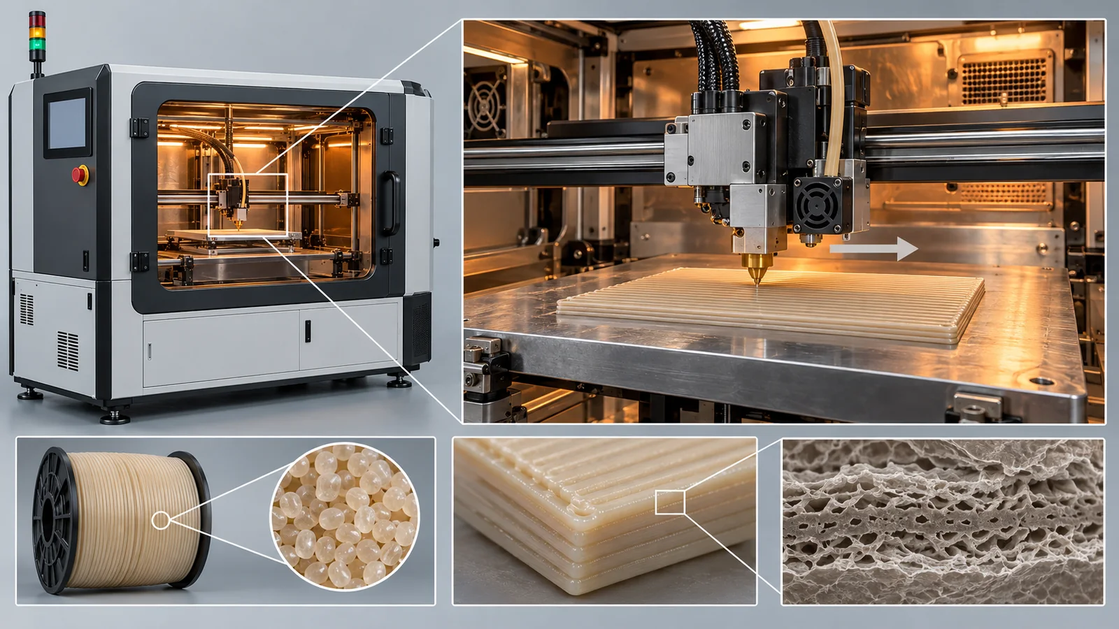
An electrostatic analyzer printed in CNT-filled PEEK
Larrick and colleagues (printing at the University of Alaska Fairbanks Geophysical Institute, residual-gas analysis at NASA Goddard) printed an electrostatic analyzer (ESA) for measuring space plasma (electrons) in PEEK with carbon nanotubes (CNT) and in plain PEEK. The nozzle was at about 420 °C, the chamber at 90 °C and the bed at 140 to 160 °C; the three electrodes that need conductivity are CNT-filled and the insulating support is PEEK. The ground-test results were as follows Sourced[Ref. 5].
- Vibration: no damage under a simulated launch (20 G GEVS profile, 20 minutes in each of two orientations). With about three times its own mass (30 g) of aluminum attached, it survived 20 minutes at 14.1 G RMS
- Outgassing: residual-gas analysis (NASA Goddard) showed no difference from the empty chamber and no problem was found. The authors say a full analysis of condensable material remains to be done
- Electron beam, UV and temperature: the pass band stayed stable when electron beams were applied at different temperatures. Under ultraviolet light (simulating Lyman-alpha) it rejected out-of-band electrons and UV photons better than a machined aluminum analyzer
- Remaining worries: charging at low energy (test results were inconsistent), the dark CNT-PEEK surface expected to reach about 100 °C in sunlight, and thermal expansion and warping
This work is at the ground-test stage and is not a report of a flight. The authors note possible large mass savings, shapes that cannot be made otherwise and simpler manufacturing and assembly. Inference: charging is a challenge common to insulating materials made conductive rather than something particular to super engineering plastics, and assessing spacecraft charging is the territory of standards such as ECSS-E-ST-20-06C [Ref. 26].
Connection to standards
NASA-STD-6030 sets requirements for additive manufacturing (AM) processes used for NASA spaceflight hardware. All crewed spaceflight hardware is covered, tailoring guidance is given for uncrewed missions, and in-space AM is also meant to be covered, though significant tailoring is expected (baseline of 21 April 2021; not a NASA mandatory standard) Sourced[Ref. 21]. ECSS has an additive manufacturing standard, ECSS-Q-ST-70-80C, but it is for metallic powder bed fusion, and we could not find an ECSS or ISO standard for plastic FDM Sourced[Ref. 25].
10. Limits, and what could not be confirmed
- PEEK's in-orbit ultraviolet and radiation numbers: we could confirm only the abstracts of the LDEF evaluation of PEEK resin and of NASA Langley's electron-beam evaluation. We give no numbers from them
- Quantity and locations of use on spacecraft: we could not confirm statistics on how much PEEK is used where on which spacecraft. The "application" field of the NASA database is the description of the party that requested the test
- Requirements for cable insulation: we confirmed that PEEK tubing has records with a cable-insulation application, but not spacecraft wiring standards or statistics on the record of PEEK-insulated wire
- An in-orbit record for 3D-printed PEEK: we could not confirm one. The CubeSat of Rinaldi and colleagues is a "proof-of-concept model" and the analyzer of Larrick and colleagues was tested on the ground
- The scope of the Ten-Koh data: the observations cover about four months (101 measurements), and there are no data after contact was lost on 19 March 2019. Long-term change cannot be inferred from these data
- The text of standards: we did not confirm the test conditions of the ISO standards (paywalled) or the text of ECSS-Q-ST-70-04C and 70-06C. For ECSS-Q-ST-70-02C we checked the relevant passages of the publicly available PDF
- ASTM: we did not open ASTM's site. ASTM E 595 is only the number and title written on NASA's page, and ASTM D 638 only the number and title written in the references of the paper by Rinaldi and colleagues
11. How to read the yardsticks and standards
Space evaluation of super engineering plastics goes beyond a table of properties: it checks one environmental factor at a time with tests reproduced on the ground. The yardsticks fall into five groups: (1) what comes out in vacuum (outgassing: TML, RML, CVCM); (2) what erodes in low orbit (erosion yield); (3) how the material changes under ultraviolet light and particles (changes in optical properties and strength); (4) temperature swings and temperature distribution (relation to the glass transition, thermal-vacuum cycling); and (5) for crewed craft, flammability and odor and toxic gas (flammability and offgassing). Each measures only one factor, whereas in space they act together. A yardstick is a tool for screening and comparing materials; it does not directly predict lifetime in orbit.
| What is evaluated | Typical test or method (name, source) | Standards and guidance (ECSS, ISO, NASA and others) | Cautions in reading |
|---|---|---|---|
| Outgassing (TML, RML, CVCM) | A test measuring mass loss and condensed amount in vacuum at 125 °C for 24 hours. NASA calls it ASTM E 595 Sourced[Ref. 1, 14]. Results are searchable in the NASA Goddard database. Printed PEEK was tested in ESA/ESTEC's µVCM apparatus [Ref. 4] | ECSS-Q-ST-70-02C "Thermal vacuum outgassing test for the screening of space materials" (2008). RML < 1.0 % and CVCM < 0.10 % are the minimum screening values Sourced[Ref. 13] | Values change with grade, shape and pre-treatment (Chapter 5). Screening is for selection, not a lifetime guarantee |
| Atomic oxygen (erosion yield) | In orbit: the PEACE Polymers of MISSE (fluence calibrated with Kapton H) Sourced[Ref. 1]. On the ground: plasma asher (NASA refers to ASTM E 2089-00). Work that corrects by the ratio to in-orbit values [Ref. 2] | ISO 15104:2025 "Space systems — Environmental testing for spacecraft thermal control materials" (ground-test methods for atomic oxygen, particle radiation, ultraviolet light and thermal cycling; aimed at thermal control materials; published January 2025) Sourced[Ref. 16] | The dose differs by orders of magnitude with orientation (forward or backward) and altitude (Chapter 6). Ground tests and in-orbit values may not agree |
| Ultraviolet, particle and gamma radiation | Ground simulated irradiation with property measurements before and after. In orbit: MISSE-9 and 10 (ultraviolet 720 and 561 equivalent sun hours) Sourced[Ref. 6]. A summary of radiation resistance: the abstract by Sasuga [Ref. 7] | ECSS-Q-ST-70-06C "Particle and UV radiation testing for space materials" (2008) Sourced[Ref. 17]. ISO 15856:2010 "Space systems — Space environment — Simulation guidelines for radiation exposure of non-metallic materials" (gives recommended methods and practices; reconfirmed in 2026) Sourced[Ref. 15] | Check the source, the atmosphere (air or vacuum), the dose rate and the temperature (Chapter 7). ISO 15856 is "recommended" guidance |
| Temperature and thermal cycling | Dynamic mechanical analysis (DMTA; Rinaldi and colleagues measured E′ and Tg in tension mode at 1 Hz from -50 to 250 °C) Sourced[Ref. 4]. In orbit: temperature measurement on Ten-Koh [Ref. 3] | ECSS-Q-ST-70-04C "Thermal testing for the evaluation of space materials, processes, mechanical parts and assemblies" (2008) Sourced[Ref. 18]. We could not confirm a standard for DMTA | Read the material's Tg together with the part's temperature distribution (thermal analysis) (Chapter 8) |
| Mechanical properties (tensile, flexural) | Rinaldi and colleagues made tensile specimens as ASTM D 638 Type V and flexural specimens to ASTM D 790 dimensions (as stated in the paper; the title of D 638 in the paper's references is "Standard Test Method for Tensile Properties of Plastics") Sourced[Ref. 4] | ECSS-E-ST-32-08C Rev.1 "Space engineering — Materials" (2014; the standard for mechanical requirements on materials; text not checked) [Ref. 27] | Printed parts change with specimen orientation and print conditions. Do not set them beside datasheet values (injection molding) |
| Flammability and offgassing for crewed craft | Tests of how well a material resists burning and of the trace toxic gases it gives off into living space | NASA-STD-6001 "Flammability, Offgassing, and Compatibility Requirements and Test Procedures" (Version B with Change 3) Sourced[Ref. 22]. ECSS-Q-ST-70-21C (flammability screening) [Ref. 23]. ECSS-Q-ST-70-29C (offgassing in a crew compartment) [Ref. 24] | The aim differs from vacuum outgassing (contamination). We did not check the requirements in the text |
| Additive-manufacturing process | Checking print conditions and specimen properties (Rinaldi and colleagues, Larrick and colleagues) | NASA-STD-6030 (baseline 2021) Sourced[Ref. 21]. ECSS-Q-ST-70-80C covers metallic powder bed fusion [Ref. 25]. We could not confirm one for plastic FDM | A standard sets requirements for process control. Test values are still needed for each material, machine and set of conditions |
| Material selection and approval procedure | Preparing material data and controlling approval of use Sourced[Ref. 19] | ECSS-Q-ST-70-71C Rev.1 (2019) [Ref. 19]. NASA-STD-6016 (Version C with Change 1; dated 30 September 2021; shown as a NASA Endorsed Standard but not mandatory) [Ref. 20] | Which standard applies is set by contract for each project. We did not check the requirements in the text |
The arrangement of this table is Our calculation (our own reordering). Standard numbers, titles and status were checked on the official pages of ECSS, ISO and NASA (checked 17 October 2026). For ASTM we give only the numbers and titles written in NASA reports or papers; we did not open ASTM's site. ISO texts are paywalled, so we limited ourselves to titles and scope.
Cautions in reading (for materials engineers)
- Ground tests and flight results are different things: Ten-Koh's four months and MISSE-9 and 10's 198 to 250 days are valuable in-orbit data, but they are limited in time and orbit. AO changes by orders of magnitude with orientation
- A database "record" is not a "product guarantee": a NASA record is a test result for one lot at one time, and products with the same name change with pre-treatment (Chapter 5)
- Check whether a standard is a recommendation or a requirement: ISO 15856 is recommended guidance. NASA-STD-6016 and 6030 are shown as not NASA mandatory standards. An ECSS standard becomes a requirement when a contract applies it, and it can be tailored
- A proof of concept and a qualified flight part are different: the CubeSat structure of Rinaldi and colleagues is a "proof-of-concept model" and the analyzer of Larrick and colleagues was ground-tested; neither is reported as having passed qualification testing as a flight part
12. Glossary
- Super engineering plastic
- A name for resins with higher heat resistance, strength and chemical resistance than general engineering plastics. Not defined by law or standard.
- PEEK
- Polyetheretherketone. A crystalline super engineering plastic. Tg about 143 °C and melting point about 343 °C (datasheet values).
- PEKK
- Polyetherketoneketone. A resin with a structure close to PEEK's. A CNT-filled ESD grade was tested outside the ISS.
- PEI
- Polyetherimide (trade name Ultem). An amorphous super engineering plastic.
- PPS, LCP
- Polyphenylene sulfide and liquid crystal polymer. Many NASA records show little gas release.
- PAI, PBI
- Polyamide-imide (Torlon) and polybenzimidazole. Some records show large TML from absorbed water.
- CF/PEEK
- PEEK composite reinforced with carbon fiber. A light structural material with low thermal expansion.
- Glass transition (Tg)
- A guide to the temperature at which a hard state turns soft. Above it, stiffness drops sharply.
- DMTA
- Dynamic mechanical thermal analysis. Measures modulus (E′) and other properties while changing temperature, to find Tg.
- Thermal conductivity
- How well heat is conducted. PEEK 0.25, aluminum 170 W/m·K.
- CTE
- Coefficient of thermal expansion. The fractional change in length per 1 °C.
- Outgassing
- A material releasing gas in vacuum.
- TML, RML, WVR, CVCM
- Total mass loss; mass loss excluding water (TML - WVR); water vapor regained; and the amount condensed.
- Atomic oxygen (AO)
- Oxygen atoms floating in low orbit. They erode polymer surfaces.
- Erosion yield
- The volume of material lost per oxygen atom (cm3 per atom). Smaller means harder to erode.
- Equivalent sun hours (ESH)
- The amount of ultraviolet light expressed as hours in the Sun.
- FDM / FFF
- 3D-printing methods that push softened plastic through a nozzle and stack it.
- CubeSat (2U)
- A small satellite built on a 10 cm cube (1U). A 2U is about 10 × 10 × 20 cm.
- ESD
- Electrostatic discharge. ESD plastics are tuned to a resistivity that lets static charge leak away.
- MISSE
- NASA's series of experiments that expose materials outside the ISS.
- Wake / nadir / ram
- Backward-facing / Earth-facing / forward-facing. The AO dose differs by orders of magnitude between them.
- ECSS
- European Cooperation for Space Standardization. Europe's cooperative body for space standards.
13. References
- de Groh K. K. et al. (NASA Glenn) "MISSE PEACE Polymers Atomic Oxygen Erosion Results", NASA/TM—2006-214482 (November 2006) — ntrs.nasa.gov/citations/20070002707
- Stambler A. H. et al. (NASA Glenn) "Ground-Laboratory to In-Space Atomic Oxygen Correlation for the Polymer Erosion and Contamination Experiment (PEACE) Polymers", NASA/TM—2011-216904 (January 2011) — ntrs.nasa.gov/citations/20110006367
- Abdullah F., Okuyama K., Fajardo I., Urakami N. (Kyushu Institute of Technology) "In Situ Measurement of Carbon Fibre/Polyether Ether Ketone Thermal Expansion in Low Earth Orbit", Aerospace 7(4), 35 (2020), DOI 10.3390/aerospace7040035 — doi.org/10.3390/aerospace7040035
- Rinaldi M. et al. (University of Rome Tor Vergata, Thales Alenia Space Italia, ESA/ESTEC) "Additive Manufacturing of Polyether Ether Ketone (PEEK) for Space Applications: A Nanosat Polymeric Structure", Polymers 13(1), 11 (2021), DOI 10.3390/polym13010011 (open access) — doi.org/10.3390/polym13010011
- Larrick Q. et al. "Additively Manufactured Plastic Plasma Spectrometer" (electrostatic analyzer printed in CNT-filled PEEK; NASA Technical Reports Server, 2024) — ntrs.nasa.gov/citations/20240014082
- Finckenor M. M., McElderry J. R. (NASA Marshall) "Space Environmental Effects on Additively Manufactured Materials – Results from MISSE-9 and MISSE-10", NASA/TM–20230008474 (July 2023) — ntrs.nasa.gov/citations/20230008474
- Sasuga T. "High temperature irradiation effect on fully aromatic polymers" (abstract on radiation resistance of aromatic polymers; 1988, IEEJ insulating materials research group; checked in the INIS record; in Japanese) — inis.iaea.org/records/za72j-pp962
- Funk J. G., Sykes G. F. Jr. "Space radiation effects on poly(aryl-ether-ketone) thin films and composites" (1988; abstract only) — ntrs.nasa.gov/citations/19880054320
- Whitaker A. F., Finckenor M. M., Kamenetzky R. R. "Property changes induced by the space environment in polymeric materials on LDEF" (1992; abstract only) — ntrs.nasa.gov/citations/19920045605
- NASA "Investigation of microstructural changes in polyetherether-ketone films at cryogenic temperatures by positron lifetime spectroscopy" (1991; abstract only) — ntrs.nasa.gov/citations/19910008903
- Theiler G., Gradt T. (BAM) "MoS2-Filled PEEK Composite as a Self-Lubricating Material for Aerospace Applications", 40th Aerospace Mechanisms Symposium (2010; abstract only) — ntrs.nasa.gov/citations/20100021916
- Delzeit L. D., Vance J. R., Shaw A. "Engineering Polymers as Structural Materials in Spacecraft Water Systems" (2021; abstract only) — ntrs.nasa.gov/citations/20210024171
- ECSS ECSS-Q-ST-70-02C "Thermal vacuum outgassing test for the screening of space materials" (15 November 2008; checked on the ECSS page and PDF) — ecss.nl/standard/ecss-q-st-70-02c-thermal-vacuum-outgassing-test-for-the-screening-of-space-materials/
- NASA Goddard Outgassing Database (searchable test results; checked 17 October 2026) — outgassing.nasa.gov/
- ISO ISO 15856:2010 "Space systems — Space environment — Simulation guidelines for radiation exposure of non-metallic materials" (edition 1, August 2010; reconfirmed in 2026; checked on the ISO page) — iso.org/standard/45843.html
- ISO ISO 15104:2025 "Space systems — Environmental testing for spacecraft thermal control materials" (edition 1, January 2025; checked on the ISO page) — iso.org/standard/84447.html
- ECSS ECSS-Q-ST-70-06C "Particle and UV radiation testing for space materials" (31 July 2008) — ecss.nl/standard/ecss-q-st-70-06c-particle-and-uv-radiation-testing-for-space-materials/
- ECSS ECSS-Q-ST-70-04C "Thermal testing for the evaluation of space materials, processes, mechanical parts and assemblies" (15 November 2008) — ecss.nl/standard/ecss-q-st-70-04c-thermal-testing-for-the-evaluation-of-space-materials-processes-mechanical-parts-and-assemblies/
- ECSS ECSS-Q-ST-70-71C Rev.1 "Materials, processes and their data selection" (15 October 2019) — ecss.nl/standard/ecss-q-st-70-71c-rev-1-materials-processes-and-their-data-selection-15-october-2019/
- NASA NASA-STD-6016 "Standard Materials and Processes Requirements for Spacecraft" (Version C with Change 1; dated 30 September 2021, changed 15 November 2023; checked on the NASA Standards page) — standards.nasa.gov/standard/NASA/NASA-STD-6016
- NASA NASA-STD-6030 "Additive Manufacturing Requirements for Spaceflight Systems" (baseline, 21 April 2021; checked on the NASA Standards page) — standards.nasa.gov/standard/NASA/NASA-STD-6030
- NASA NASA-STD-6001 "Flammability, Offgassing, and Compatibility Requirements and Test Procedures" (Version B with Change 3; dated 26 August 2011, changed 9 June 2025; checked on the NASA Standards page) — standards.nasa.gov/standard/NASA/NASA-STD-6001
- ECSS ECSS-Q-ST-70-21C "Flammability testing for the screening of space materials" (5 February 2010) — ecss.nl/standard/ecss-q-st-70-21c-flammability-testing-for-the-screening-of-space-materials-5-february-2010/
- ECSS ECSS-Q-ST-70-29C "Determination of offgassing products from materials and assembled articles to be used in a manned space vehicle crew compartment" — ecss.nl/standard/ecss-q-st-70-29c-determination-of-offgassing-products-from-materials-and-assembled-articles-to-be-used-in-a-manned-space-vehicle-crew-compartment/
- ECSS ECSS-Q-ST-70-80C "Processing and quality assurance requirements for metallic powder bed fusion technologies for space applications" (30 July 2021; covers metallic powder bed fusion) — ecss.nl/standard/ecss-q-st-70-80c-processing-and-quality-assurance-requirements-for-metallic-powder-bed-fusion-technologies-for-space-applications-30-july-2021/
- ECSS ECSS-E-ST-20-06C Rev.1 "Spacecraft charging" (15 May 2019) — ecss.nl/standard/ecss-e-st-20-06c-rev-1-spacecraft-charging-15-may-2019/
- ECSS ECSS-E-ST-32-08C Rev.1 "Space engineering - Materials" (15 October 2014) — ecss.nl/standard/ecss-e-st-32-08c-rev-1-space-engineering-materials-15-october-2014/
14. Claim-to-source audit
| Claim in the text | Basis | Class |
|---|---|---|
| The in-orbit CTE measurement of three CF/PEEK samples on Ten-Koh (launched 29 October 2018, altitude about 600 km): 101 measurements (9 November 2018 to 19 March 2019), sample temperature -40 to 20 °C, no shift in about four months, loss of contact, thermal welding, and the use of CF/PEEK for the external structure of Shinen-2 | Abdullah et al. (Aerospace 2020) Reference 3 https://doi.org/10.3390/aerospace7040035 | Sourced |
| Mechanical properties, density, DMTA (E′ 3.9 to 2.3 GPa, Tg 153 °C) and outgassing (TML 0.19, RML 0.11, CVCM 0.01 %) of 3D-printed PEEK (nozzle 410 °C, bed 120 °C). The thermal analysis of a CubeSat (aluminum 245 to 246 K, PEEK 224 to 414 K, required conductivity about 5 W/m·K). The datasheet values for PEEK (Tg 143 °C, thermal conductivity 0.25 and so on) | Rinaldi et al. (Polymers 2021) Reference 4 https://doi.org/10.3390/polym13010011 | Sourced |
| Ground tests of the electrostatic analyzer printed in CNT-filled PEEK (vibration, residual-gas analysis, electron beam and ultraviolet light, charging and thermal concerns) | Larrick et al. (NASA Technical Reports Server) Reference 5 https://ntrs.nasa.gov/citations/20240014082 | Sourced |
| Tests of printed PEI, PEKK and polycarbonate on MISSE-9 and 10 (exposure period, ultraviolet light, thermal cycles, AO, changes in tensile stress, changes in mass, optical properties and resistivity, no impact marks, and why ABS was not chosen) | NASA/TM–20230008474 Reference 6 https://ntrs.nasa.gov/citations/20230008474 | Sourced |
| The erosion yields in MISSE 2 PEACE Polymers (PEEK 2.99, Kapton H 3.00, PSU 2.94, PEI > 3.31, PBI > 2.21, PMR-15 > 3.02, FEP 0.200, PTFE 0.142 × 10⁻²⁴ cm3 per atom), calibration with Kapton H, and the study of correlation with ground tests | NASA/TM—2006-214482, NASA/TM—2011-216904 Reference 1 https://ntrs.nasa.gov/citations/20070002707 Reference 2 https://ntrs.nasa.gov/citations/20110006367 | Sourced |
| Records in the NASA Goddard database (TML, CVCM and WVR of PEEK, PPS, LCP, PEI, PES, PAI, polyimide and PBI; application field: sensor frame, isolator, cable insulation, shrink tubing, ring seal). That the test method is ASTM E 595 | NASA Goddard Outgassing Database (checked 17 October 2026) Reference 14 https://outgassing.nasa.gov/ | Sourced |
| The outgassing test conditions, the definition of RML, RML < 1.0 % and CVCM < 0.10 %, and that the TML of water-absorbing materials is often above 1.0 % | The PDF and official page of ECSS-Q-ST-70-02C Reference 13 https://ecss.nl/standard/ecss-q-st-70-02c-thermal-vacuum-outgassing-test-for-the-screening-of-space-materials/ | Sourced |
| The order of radiation resistance of aromatic polymers (imide ring > diphenyl ether-diphenyl ketone > ...), deterioration at 1/5 to 1/10 of the dose with oxygen, and cross-linking versus main-chain scission in PEEK | Abstract of Sasuga (1988) Reference 7 https://inis.iaea.org/records/za72j-pp962 | Sourced |
| The evaluation of PEEK thin films and composites under electron radiation and thermal cycling equal to 30 years in geosynchronous orbit, the evaluation of PEEK resin on LDEF, the decrease in free volume of PEEK at -196 °C, the friction coefficient of MoS2-filled PEEK, and the study of water systems | Funk and Sykes, Whitaker et al., the 1991 NASA report, Theiler and Gradt, Delzeit et al. (abstracts only in every case) Reference 8 https://ntrs.nasa.gov/citations/19880054320 Reference 9 https://ntrs.nasa.gov/citations/19920045605 Reference 10 https://ntrs.nasa.gov/citations/19910008903 Reference 11 https://ntrs.nasa.gov/citations/20100021916 Reference 12 https://ntrs.nasa.gov/citations/20210024171 | Sourced |
| The RML in Fig. 4, the "vs Kapton H" ratios in Fig. 5, the ratios in Fig. 8, the estimates of PEEK erosion (64 µm per year, years to lose 0.5 mm and 2 mm), the ratio of AO doses (about one 280th or less), and the percentage changes in tensile stress of Ultem 1010 and others | Our calculation (assumptions in the text). Not measured results | Our calculation |
| The titles, scope and status of ISO 15856:2010 and ISO 15104:2025 | ISO official pages Reference 15 https://www.iso.org/standard/45843.html Reference 16 https://www.iso.org/standard/84447.html | Sourced |
| The titles and scope of ECSS-Q-ST-70-04C, 70-06C, 70-21C, 70-29C, 70-71C Rev.1, 70-80C, ECSS-E-ST-20-06C Rev.1 and ECSS-E-ST-32-08C Rev.1 | ECSS official pages Reference 18 https://ecss.nl/standard/ecss-q-st-70-04c-thermal-testing-for-the-evaluation-of-space-materials-processes-mechanical-parts-and-assemblies/ Reference 17 https://ecss.nl/standard/ecss-q-st-70-06c-particle-and-uv-radiation-testing-for-space-materials/ Reference 23 https://ecss.nl/standard/ecss-q-st-70-21c-flammability-testing-for-the-screening-of-space-materials-5-february-2010/ Reference 24 https://ecss.nl/standard/ecss-q-st-70-29c-determination-of-offgassing-products-from-materials-and-assembled-articles-to-be-used-in-a-manned-space-vehicle-crew-compartment/ Reference 19 https://ecss.nl/standard/ecss-q-st-70-71c-rev-1-materials-processes-and-their-data-selection-15-october-2019/ Reference 25 https://ecss.nl/standard/ecss-q-st-70-80c-processing-and-quality-assurance-requirements-for-metallic-powder-bed-fusion-technologies-for-space-applications-30-july-2021/ Reference 26 https://ecss.nl/standard/ecss-e-st-20-06c-rev-1-spacecraft-charging-15-may-2019/ Reference 27 https://ecss.nl/standard/ecss-e-st-32-08c-rev-1-space-engineering-materials-15-october-2014/ | Sourced |
| The titles, scope and status of NASA-STD-6016, 6030 and 6001, and that 6016 and 6030 are not NASA mandatory standards | NASA Standards official pages Reference 20 https://standards.nasa.gov/standard/NASA/NASA-STD-6016 Reference 21 https://standards.nasa.gov/standard/NASA/NASA-STD-6030 Reference 22 https://standards.nasa.gov/standard/NASA/NASA-STD-6001 | Sourced |
| Readings such as "outgassing is a property of material, pre-treatment and shape", "printed PEEK becomes a PEEK that does not stretch", "maximum service temperature is a material's number, temperature distribution a design's number", "check the atmosphere of a radiation test" and "a thermoplastic opens a path without adhesive" | This article's organization and commentary based on published content. Not views stated by any of the organizations | Commentary |
| PEEK's in-orbit ultraviolet and radiation numbers, the quantity of use on spacecraft, the record of PEEK-insulated wire, an in-orbit record of printed PEEK, the text of ISO standards, the test conditions of ECSS-Q-ST-70-04C and 70-06C, and a standard for DMTA | Not confirmed within the range of primary sources this article could reach, so not stated | Commentary |
| That, of Figs. 1 to 9, Figs. 1 and 9 (AI image frames) are illustrative concept images, and that the other figures are drawings for explanation, not observations of real data | A note by this article | Commentary |
Last updated: 17 October 2026 / Sources are limited to primary materials (NASA technical reports, the NASA Goddard database, peer-reviewed papers, the official pages of ECSS, ISO and NASA, and an INIS record). In-orbit measurements are values under the conditions reported and do not carry over to other orbits or periods. Calculated and analyzed values rest on the assumptions of this article or of the papers cited, are illustrative, and do not predict the lifetime or temperature of real hardware. We could not confirm PEEK's in-orbit ultraviolet and radiation numbers, the quantity of use on spacecraft, an in-orbit record for printed PEEK, or the test conditions in the standards' texts, so we do not state them.