TECHNOLOGY EXPLAINER
Thermal Protection Systems
— Ablators, ceramic tiles and heat-resistant composites that carry vehicles through re-entry
A vehicle returning from space plunges into the atmosphere at more than 7 km per second. A layer of hot gas forms ahead of it, and the surface sees thousands of degrees. Written for materials engineers who know little about space engineering, this article uses diagrams to explain why it gets hot, how the heat is shed (ablation, radiation, heat sink), the Shuttle's silica tiles and reinforced carbon-carbon, the ablators (Avcoat, PICA) of Orion and Stardust, and how a stainless-steel vehicle is protected. Failures (Columbia, and the char loss on Artemis I) are read through a materials lens, within the scope of the official investigations.
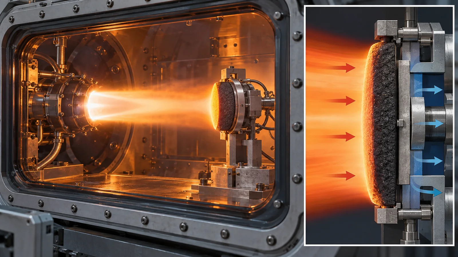
- The short version / what to know first / where this fits
- Why it gets hot: compressed hot gas
- How the heat is shed: four concepts
- Radiation can shed only so much
- Ablators: protection by wearing away (PICA, Avcoat)
- Reusable silica tiles and heat-resistant composites
- Learning from damage: Columbia and Artemis I
- Heat protection for a stainless-steel vehicle
- Testing on the ground: arc jets and flight data
- How to read the yardsticks and standards / glossary / references / claim-to-source audit
Sourced = stated in a published source (linked)
Our calculation = a value this article calculated from stated assumptions
Not yet confirmed = company targets, plans, drafts of standards, and other items not yet settled
Our own reading for materials engineers is marked as commentary. Inference is shown in bold. Every analogy comes with a note on where it stops working.
Temperatures, heat fluxes and speeds depend on the vehicle, mission and test conditions. "3,000 °F" appears with two different meanings: the exterior temperature reached on Shuttle re-entry and the maximum-use temperature of RCC. Values under different conditions are not ranked against each other. Demonstration data carry the vehicle name, date and conditions (ground test or flight). Figs. 3 and 5 are explanatory values we calculated. Re-entry failures and accidents are described neutrally within official investigation reports and agency statements, and causes are not asserted by inference. This field changes fast, so statuses carry a check date (17 October 2026). Military applications are not covered.
1. The short version, what to know first, and where this fits
- The star of the heat is compressed hot gas. Low-orbit speed is about 17,500 mph (about 7.8 km/s), and the kinetic energy is about 30 MJ per kilogram, about 46 times the energy needed to warm aluminum from room temperature to its melting point.Our calculation[Refs. 23, 25] The vehicle takes this heat from the hot gas ahead of it.
- There are four ways to get rid of it: wear away and carry it off (ablators), radiate it as light (heat-resistant tiles and the like), store it in thick metal (heat sink), or cool with a coolant or seeping gas. Real vehicles rely mainly on either single-use ablators or reusable tiles and heat-resistant composites.Sourced[Ref. 2]
- The material is decided by properties, process and attachment. The Shuttle tile is mostly air (94% by volume) and needed a compliant mount. On Artemis I, NASA reported that how easily gas escapes from the Orion ablator was behind the char loss.Sourced[Refs. 1, 11]
No space knowledge is needed. Knowing what temperature is, how heat travels (convection and radiation) and that materials expand when heated is enough. The orbital speed is given in numbers in Section 2. Equations are kept to a minimum, explained in words and checked with numbers.
Read it after the series overview and "space environment and materials", and together with the rocket basics and reusable rockets explainers the path to re-entry connects. Shedding heat as light in space is covered in thermal control materials and radiative cooling, thermal management on orbit in spacecraft thermal control, carbon-fiber composites in CFRP and composites for space, and polymers in polyimides for space.
2. Why it gets hot: compressed hot gas
First, the speed. SpaceX says staying in low orbit needs a sideways speed of about 17,500 mph (about 7.8 km/s).Sourced[Ref. 23] NASA says the Shuttle orbiter re-entered at over 17,000 mph,Sourced[Ref. 1] and that Apollo returned from the Moon at more than 25,000 mph.Sourced[Ref. 1] The Stardust capsule re-entered at 12.6 km/s.Sourced[Ref. 5]
At this speed, the air ahead cannot get out of the way and is compressed, forming a layer of hot gas behind a shock wave. The vehicle takes heat from this hot gas. The ECSS handbook says the thermal loads on a protection system are characterized by very large heat fluxes during relatively short times, and that the surrounding flow is hypersonic, three-dimensional and reactive (involving chemical reactions).Sourced[Ref. 2]
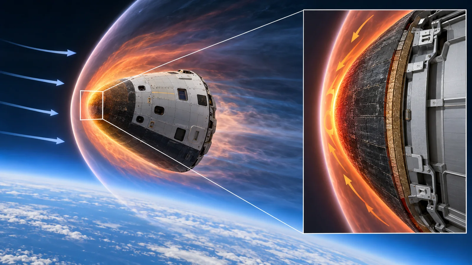
View original SVG, values and sources
Original SVG reference: Conceptual diagram (vector drawing). Schematic of why re-entry is hot, centered on compression heating of the gas. The point that it is not friction heat is our commentary.
The "friction" explanation is common and appears in NASA material too.Sourced[Ref. 1] The main actor, however, is heat reaching the surface from hot gas compressed ahead of the vehicle (our commentary). It is like the nozzle of a bicycle pump warming up because the air is compressed, not mainly because of rubbing inside the pump. Where the analogy stops: a pump compresses slowly; in re-entry, besides compression, the gas also dissociates and ionizes, and at high speed radiation joins in.
(1) Seeing the energy of speed in numbers
The kinetic energy per kilogram is ½ × speed squared. At about 7.82 km/s it is about 30.6 MJ (about 8.5 kWh).Our calculation Meanwhile, warming solid aluminum from 298 K to its melting point of 933 K takes about 0.67 MJ/kg, calculated from NIST-JANAF heat-capacity data.Our calculation[Ref. 25] So the kinetic energy at orbital speed is about 46 times the energy needed to warm aluminum to its melting point; for a lunar return (about 11.2 km/s) about 94 times, and for Stardust (12.6 km/s) about 119 times.Our calculation
More detail: the calculation
Speed conversion uses 1 mph = 0.44704 m/s. 17,500 mph = 7.823 km/s and 25,000 mph = 11.176 km/s. Kinetic energies: 7.823² / 2 = 30.6, 11.176² / 2 = 62.5 and 12.6² / 2 = 79.4 (all MJ/kg).Our calculation For aluminum, the NIST-JANAF solid heat-capacity equation (298 to 933 K) was integrated to give an enthalpy rise of about 17.97 kJ/mol, divided by the molar mass of 26.98 g/mol (about 0.666 MJ/kg).Our calculation[Ref. 25] The heat of fusion is not included. The heat that actually enters the vehicle is a fraction of the kinetic energy, and that fraction was not checked in this article.
3. How the heat is shed: four concepts
The ECSS handbook divides re-entry thermal protection into ablation, radiation, heat sink and transpiration cooling.Sourced[Ref. 2] The figure summarizes each.
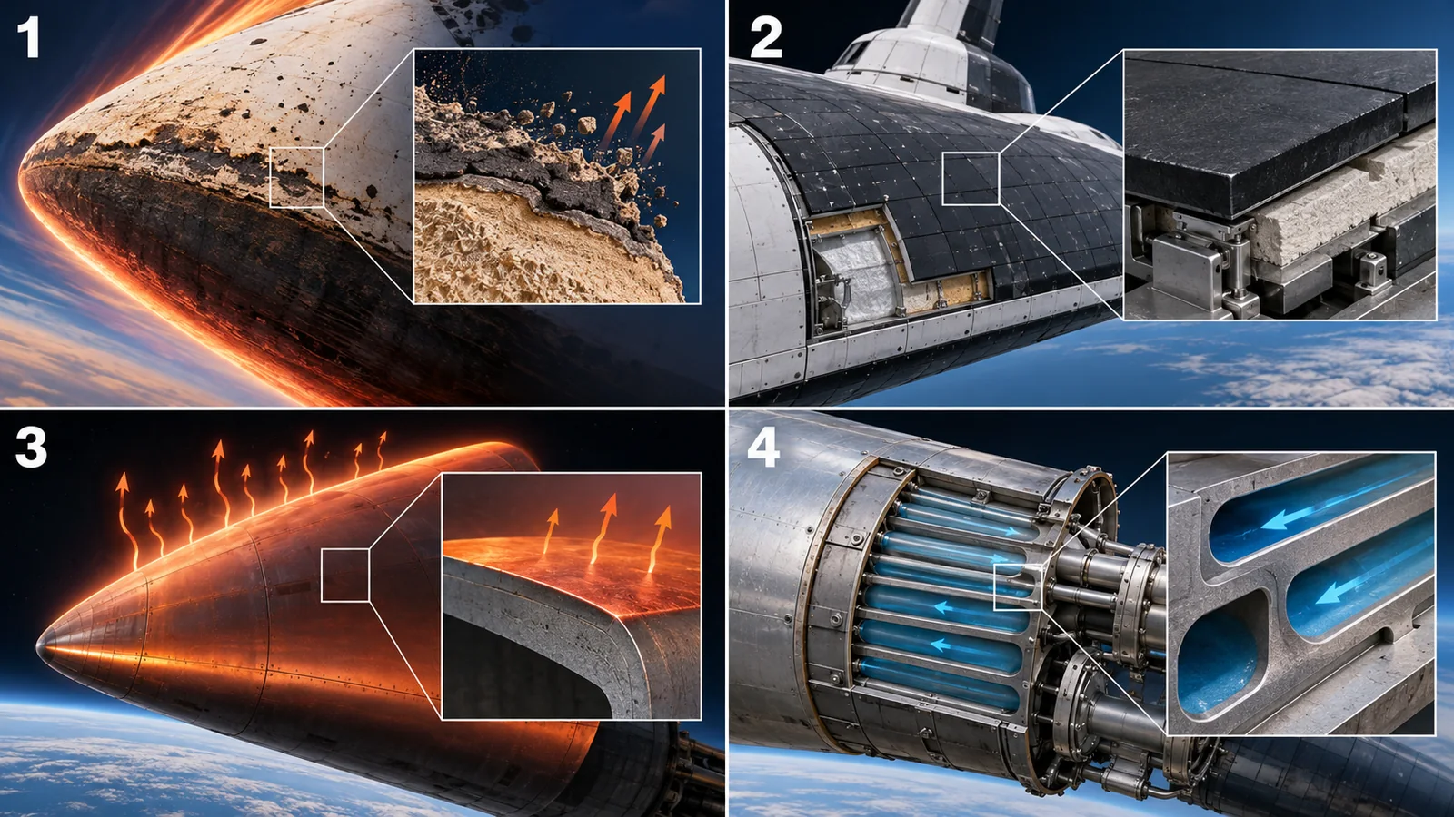
View original SVG, values and sources
Original SVG reference: Conceptual diagram (vector drawing). The four concepts of thermal protection. Classification and descriptions follow ECSS-E-HB-31-01 Part 16A; examples are those confirmed in the references.
A closer reading of the ECSS handbook. Ablation handles heat through loss of surface material (mass loss); phase changes absorb a lot of energy, giving good thermal characteristics, but it cannot be reused. Radiation has two layers: the outer layer withstands the "radiative equilibrium temperature" (the temperature at which the incoming heat is shed as light) and the inner layer insulates the structure. A heat sink is the simplest approach, storing heat in a thick layer of high heat capacity, used on early crewed vehicles (the first two crewed Mercury flights); the melting temperature is its limit, and it is hard to apply to the large heat loads of short re-entries.Sourced[Ref. 2]
4. Radiation can shed only so much
A radiative approach, such as the Shuttle tiles, can be reused. How much can radiation alone shed? When a surface sheds heat by radiation alone, the incoming heat flux q and the surface temperature T balance as q = ε × σ × T⁴ (ε is emissivity and σ is the Stefan-Boltzmann constant, 5.670×10⁻⁸ W m⁻² K⁻⁴).Sourced[Ref. 26] This is the "radiative equilibrium temperature".
Assuming an emissivity of 0.85, at RCC's maximum-use temperature of above 3,000 °F (about 1,922 K), the heat flux radiation can shed is about 66 W/cm².Our calculation[Ref. 1] By contrast, the PICA test condition for Stardust had a peak convective heating of about 1,200 W/cm².Sourced[Ref. 6] Shedding 1,200 W/cm² by radiation alone would put the surface at about 3,970 K,Our calculation far beyond the temperature of any reusable heat-resistant material. This is a rough guide to the dividing line: ablators are used where the heat flux is large, while tiles work where it is lower, as in a gliding return from orbit (our commentary).
The heat radiation can shed grows with the fourth power of temperature. Doubling the temperature lets 16 times more heat out. Put the other way, a tenfold higher heat flux raises the surface temperature only about 1.8 times (10 to the power 0.25). So for a radiating material, how high a temperature it withstands is decisive, and even a small gain in temperature capability greatly increases the heat shed. Where the analogy stops: this formula assumes an ideal case with no heat going elsewhere (no conduction into the interior); a real tile also has its insulation thickness and conduction designed.
5. Ablators: protection by wearing away (PICA, Avcoat)
An ablator protects a vehicle by deliberately wearing away. NASA describes Avcoat, the main material of the Orion heat shield, as a material designed to wear away as it heats up.Sourced[Ref. 13] Materials fall roughly into these groups. The ECSS handbook lists carbon phenolic (a high-strength charring ablator, used on the Galileo probe), silica phenolic (selected for the Huygens probe), phenolic nylon, graphite, silicone polymers, Teflon and AVCOAT 5026 used on the Apollo capsules, and says almost all heat shields are made of carbon-based materials.Sourced[Ref. 2]
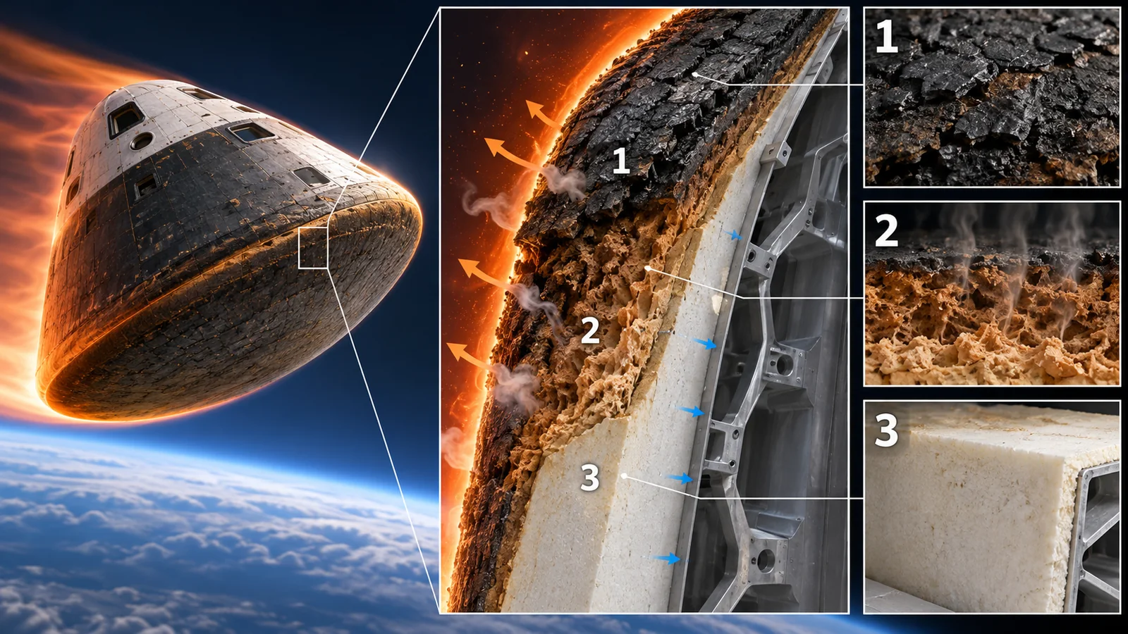
View original SVG, values and sources
Original SVG reference: Conceptual diagram (vector drawing). Schematic cross-section of an ablator. The heat-shedding functions organize the ECSS handbook; the cause of spalling is NASA's report. Layer thicknesses are illustrative.
(1) PICA: a light carbon skeleton soaked with resin
PICA (Phenolic Impregnated Carbon Ablator) is a carbon-fiber skeleton (FiberForm) soaked with phenolic resin. Its density is a light 0.27 g/cm³ and it ablates efficiently under large heat fluxes.Sourced[Ref. 9] NASA Ames developed it in the Lightweight Ceramic Ablators program, and it served as a single-piece forebody heat shield on Stardust. A 1996 paper said the Stardust re-entry at 12.6 km/s would be the fastest to date.Sourced[Ref. 5]
PICA was tested in arc jets that simulated the Stardust condition (peak convective heating of 1,200 W/cm² at 0.5 atm), and a code's predictions of recession and internal temperature were matched by adjusting material properties.Sourced[Ref. 6] In another exploratory test at a cold-wall heat flux of about 1,800 W/cm² and a stagnation pressure of 130 kPa, all samples survived.Sourced[Ref. 7] On the other hand, PICA has good thermal properties but is structurally weak; fracture tests showed cracks starting and growing in the phenolic phase.Sourced[Ref. 8] PICA has been used on Stardust, the Mars Science Laboratory (MSL) and Dragon.Sourced[Ref. 8]
On MSL, temperatures inside the heat shield were measured with thermocouples. The data show that the boundary layer transition (when the flow becomes turbulent) occurred at 5 of 7 thermocouple locations before peak heating.Sourced[Ref. 17] It is an example of comparing design assumptions (a fully turbulent heat pulse) with real flight data.
(2) Avcoat: resin filling a honeycomb
Avcoat descends from AVCOAT 5026 used on the Apollo capsules.Sourced[Ref. 2] The heat shield of Orion's first flight test, EFT-1 (2014), followed the Apollo approach and was a single piece made by filling each cell of a honeycomb (a cellular skeleton) with ablator using dedicated injection guns.Sourced[Ref. 10] EFT-1 experienced about 80% of the lunar-return velocity and about 50% of the lunar-return heating rate.Sourced[Ref. 10] For Artemis I (EM-1) in 2022, the Avcoat was changed to blocks (tiles) bonded to a composite skin, on a carrier structure of a titanium skeleton and composite skin.Sourced[Ref. 10]
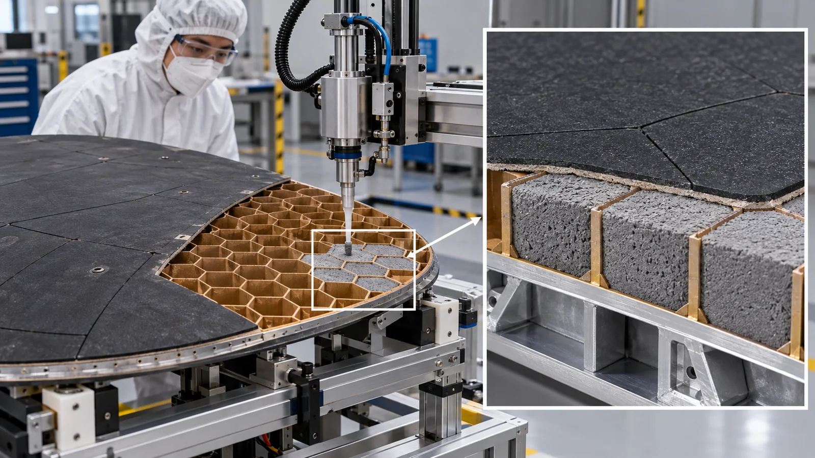
Even with the same composition, injecting into a honeycomb and bonding blocks differ in how they crack and how seams are handled. A NASA document says the problem of developing a suitable gap filler for tiled PICA led the Orion program to choose Avcoat over PICA as its main material.Sourced[Ref. 9] The Artemis I case below shows that a property, how easily gas escapes (permeability), can decide a heat-shield's fate. For materials engineers it means designing and inspecting not only composition but porosity, permeability, seams and bonding (our commentary).
6. Reusable silica tiles and heat-resistant composites
The Space Shuttle needed light, reusable protection with a design life of 100 missions. NASA explains that the Mercury, Gemini and Apollo capsules were protected by heat shields of phenolic epoxy resin in a nickel-alloy honeycomb, but ablators were bonded directly to the vehicle, heavy and not reusable.Sourced[Ref. 1] The airframe was mainly aluminum, which cannot exceed 350 °F without annealing (softening); the purpose of the thermal protection system is to hold that limit.Sourced[Ref. 1]
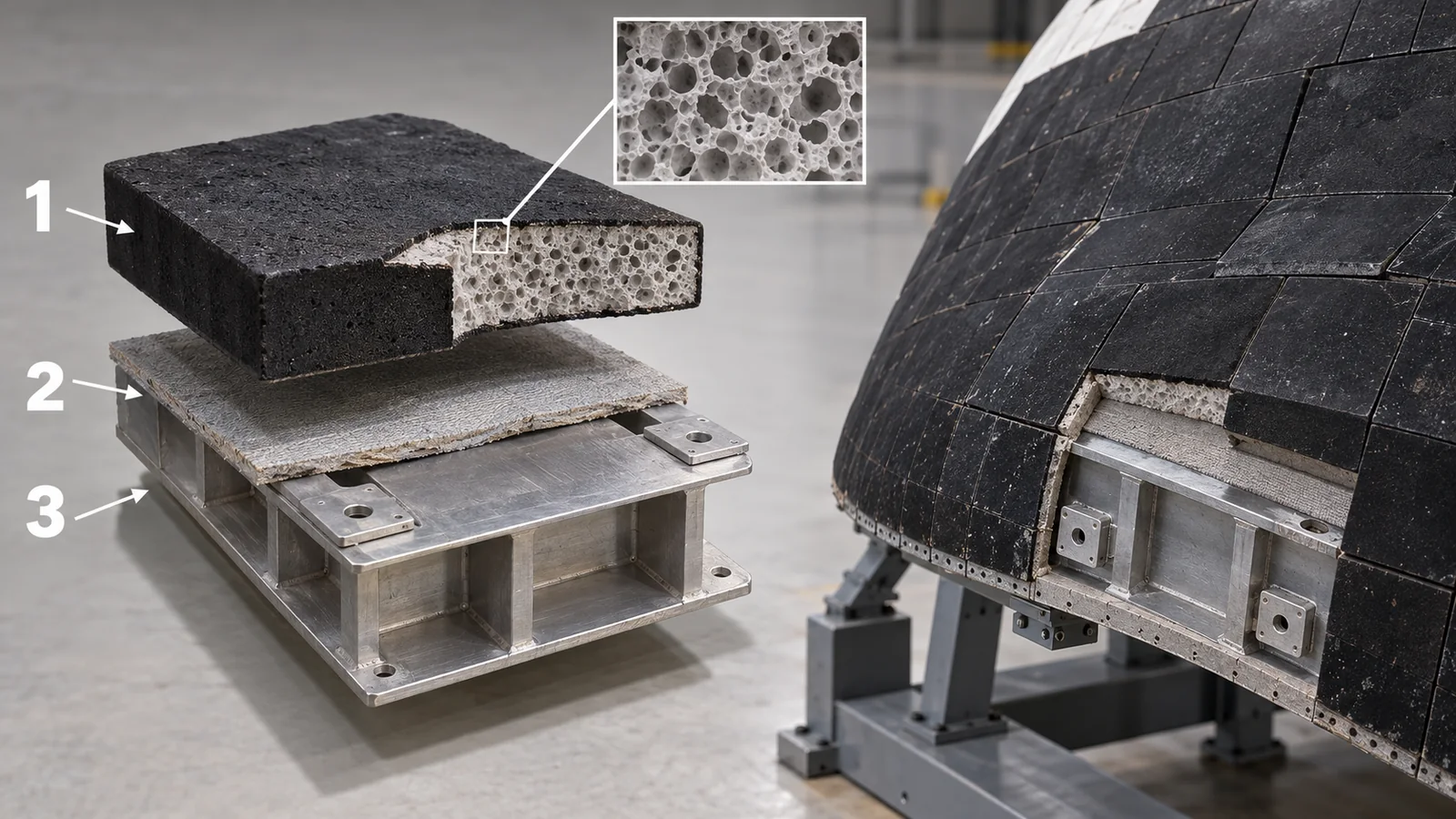
View original SVG, values and sources
Original SVG reference: Conceptual diagram (vector drawing). Schematic cross-section of a Shuttle tile. Numbers are those in NASA Facts (coating thickness, gap, temperature swing, LI-900 composition); thicknesses of the other layers are illustrative.
According to NASA Facts, most lower-surface tiles are LI-900 (a high-temperature reusable surface insulation) with a bulk density of 9 pounds per cubic foot (about 144 kg/m³), made of pure silica glass fibers 1 to 3 µm in diameter, 6% solid and 94% air by volume.Sourced [Ref. 1] It is designed to minimize thermal conductivity and mass and maximize thermal-shock resistance: it can be heated to 2,200 °F and plunged into cold water without damage. In exchange it is weak, so the higher-strength LI-2200 (22 pounds per cubic foot, about 352 kg/m³) was used around landing-gear doors and windows.Sourced[Ref. 1] The surface is covered by a coating 0.01 to 0.1 inch thick, sprayed from a glass-powder paint and fired at 2,200 °F for 90 minutes.Sourced[Ref. 1]
| Material | Bulk density (NASA Facts) | Converted (our calculation) | Role |
|---|---|---|---|
| LI-900 | 9 lb/ft³ | ≈ 144 kg/m³ | Most lower-surface tiles; light and shock-resistant but weak |
| FRCI | 12 lb/ft³ | ≈ 192 kg/m³ | Tiles in isolated areas (AETB-8 later added alumina fiber to this technology) |
| LI-2200 | 22 lb/ft³ | ≈ 352 kg/m³ | Higher-strength version around landing-gear doors and windows |
| PICA | about 0.27 g/cm³ (NASA Ames) | ≈ 270 kg/m³ | An ablator (single use); for comparison |
Converted with 1 lb/ft³ = 16.0185 kg/m³.Our calculation The FRCI 12-pound figure is from the tile-count table in NASA Facts. Densities are not a ranking, since uses and structures differ.Sourced[Refs. 1, 9]
(1) Attachment: loose and soft
Tiles are bonded to the airframe with a silicone adhesive through a strain isolator pad (a needled Nomex felt). Unlike many adhesives, silicone stays flexible in the cold part of the orbit and keeps good bond strength at re-entry temperatures. The pad limits vibration damage to the tiles during ascent and absorbs the difference in thermal expansion between tile and airframe.Sourced[Ref. 1] Gaps of 0.028 to 0.2 inch between tiles are needed to absorb the difference in expansion and contraction as the exterior temperature swings by up to about 400 °F in orbit. But if a gap is too wide, hot gas flows in during re-entry and damages the seal behind it, so gaps were controlled with "gap fillers" in many places.Sourced[Ref. 1]
Silica tiles have a small thermal expansion while the aluminum airframe moves a lot. Bonding them rigidly would build up stress with every temperature change. The Shuttle solved it by floating a low-strength material off the airframe on soft layers (pad and silicone) and gaps.Sourced[Ref. 1] Choosing the adhesive meant picking a material (silicone) that stays flexible when cold and keeps bond strength when hot. For materials engineers, not just the material's own heat resistance but managing the differences in expansion and stiffness against neighboring layers sets the system's life (our commentary).
(2) Reinforced carbon-carbon (RCC): the hottest places
The hottest places, like the nose cap and wing leading edge, used RCC (reinforced carbon-carbon). According to NASA Facts, RCC has a carbon-fiber composite substrate with layers added against oxidation: a silicon-carbide conversion coating, tetraethylorthosilane (TEOS) impregnation and a sodium silicate sealant. The maximum-use temperature is above 3,000 °F (multi-mission). Because its thermal conductivity is higher than other materials, heat moves internally by radiation from the hottest apex to cooler areas, softening temperature differences. But the internal insulation that protects the structure slows RCC cooling, so it stays hot longer, oxidizes more, and shortens the component's life.Sourced[Ref. 1]
NASA Facts covers other materials too. AFRSI (fibrous insulation blankets) sandwiches pure silica felt between a silica fabric on the hot side and an S-glass fabric, through-stitched with silica thread in a 1-inch grid; one blanket can replace up to 25 tiles. In 1996 AETB-8, with added alumina fiber, was introduced, and tougher "TUFI" tiles were used in high-impact areas such as around the engines. The tile water-repellent treatment (injection of dimethylethoxysilane) burns out at 1,050 °F, so it had to be redone after every flight.Sourced[Ref. 1]
NASA Ames later developed TUFROC (Toughened Uni-piece Fibrous Reinforced Oxidation-resistant Composite). It is described as suitable for reusable entry heating above 2,900 °F, with single-use potential to at least 3,600 °F; it was developed for the X-37 project and used as the wing leading edge of the Air Force X-37B. It is a two-layer system, from a carbon-composite surface into a Shuttle-tile-type material in depth. An improved surface treatment, Advanced TUFROC, is reported to run cooler by reducing catalytic atom recombination at the surface.Sourced[Refs. 18, 19]
In a hypersonic flow, air molecules have dissociated into atoms. When atoms recombine into molecules on a surface, they release heat. How strongly a surface promotes this reaction is its surface catalycity, and on a low-catalycity surface the heat flux drops in the same flow. The Advanced TUFROC surface treatment is based on this idea.Sourced[Ref. 19] In arc-jet testing too, the gap between cold-wall and hot-wall values depends, under some conditions, on the specimen's catalycity.Sourced[Ref. 20] Surface chemistry changes the heat flux a protection system sees (our commentary).
7. Learning from damage: Columbia and Artemis I
Damage to thermal protection can lead to loss of the vehicle. Here we organize two cases through a materials lens, within what official investigations have published. Causes are not asserted by inference.
(1) Columbia (2003): the reinforced carbon-carbon leading edge
The Columbia Accident Investigation Board (CAIB) reported that the physical cause of the loss was a breach in the thermal protection on the leading edge of the left wing. Insulating foam separated from the left bipod ramp of the external tank 81.7 seconds after launch and struck the wing near the lower half of RCC panel 8. During re-entry, superheated air entered through this breach, penetrated the leading-edge insulation and progressively melted the aluminum structure of the left wing, weakening it until aerodynamic forces caused loss of control.Sourced[Ref. 15] The Board recommended that NASA develop, validate and maintain a model able to predict the damage threshold of debris impacts on the RCC leading edge and similar parts.Sourced[Ref. 16] Foam impact tests on flat RCC panels were later compared with finite-element analysis.Sourced[Ref. 16]
(2) Orion on Artemis I (2022): char loss
Artemis I returned on 11 December 2022 using a skip re-entry (dipping into the upper atmosphere, slowing, and using lift to extend range). After splashdown, charred material on the heat shield was found to have broken off unexpectedly. NASA announced the cause on 5 December 2024: gases generated inside the Avcoat could not vent and dissipate as expected, so pressure built up, horizontal cracks formed near the surface of the char layer, and some charred material broke off.Sourced[Ref. 11]
A 2026 abstract by NASA authors concludes that the low-permeability Avcoat built up extreme internal gas pressure during the skip entry that could not adequately outgas, leading to cracking and char loss. It also reports that permeable and impermeable regions performed very differently and that ground testing reproduced the anomaly. Artemis II flew a modified trajectory without the skip, splashed down on 10 April 2026 and is reported to have had significantly reduced char loss. For Artemis III and beyond, a corrective action to make a more permeable Avcoat has been reported.Sourced[Ref. 12] This is an abstract, not a final report.
An ablator sheds heat by its resin decomposing into gas and charring. If the escape path for gas (permeability) is poor, internal pressure cracks it. The NASA abstract also points out that the material's permeability was not uniform.Sourced[Ref. 12] Manufacturing variation became a difference in flight behavior. For materials engineers, quality control of an ablator needs ways to check not only density and composition but the distribution of permeability without damage. The specific inspection method, however, could not be confirmed in this article.
8. Heat protection for a stainless-steel vehicle
The vehicles so far had an aluminum skeleton protected by tiles or ablators. In a stainless-steel vehicle, the metal itself withstands higher temperatures than aluminum, so the thickness and role of the tiles could change. However, the primary information this article could confirm is very limited. In an official update dated 15 September 2026, SpaceX says: Starship is designed to be fully reusable and built to survive re-entry; multiple Starship vehicles survived re-entry despite flight experiments that removed tiles to mimic heat-shield failures and maneuvers designed to stress the vehicle's structure; because of its size and robustness the vehicle can get through re-entry, so the company deliberately took a suborbital approach to flight testing before moving to orbital flights.Sourced[Ref. 23] (company statement)
Separate what is known from what is not. What is known: the company states that it deliberately ran experiments with tiles removed and that vehicles still survived re-entry. What is not known: the stainless-steel alloy, the tile material and structure, what temperatures reach which parts of the vehicle, and the number of reuses. These could not be confirmed in official materials. Also, re-entry from a suborbital flight is a lower-speed condition than re-entry from orbit (about 17,500 mph),Our calculation so such demonstrations do not carry the same meaning as an orbital return (our commentary). In its 15 September 2026 update SpaceX says orbital flights begin with Flight 14.Not yet confirmed[Ref. 23] The completed-launch list on its site shows Flight 14 (28 September 2026, return column "EXPENDED"),Sourced[Ref. 24] but the outcome of that re-entry is not covered in this article.
It would be wrong to say "stainless steel has a high melting point, so no thermal protection is needed." Inside a metal vehicle are propellant tanks (cryogenic liquids), people and cargo, and the aim is to protect the inside from the hot outside. Metals also lose strength at high temperature. The point is to think in terms of a combination of "the temperature the metal withstands", "insulation to protect the inside" and "a surface that sheds heat as light" (Figs. 4 and 5). What combination is best depends on vehicle design and re-entry conditions, and this article does not rank them.
9. Testing on the ground: arc jets and flight data
Thermal protection materials are tested and qualified on the ground in arc jets, which blow a hot gas stream on a specimen. NASA Ames facilities include the 60-MW Interaction Heating Facility (IHF) and the 10-MW TP3.Sourced[Refs. 21, 22] A 2025 NASA Ames short course explains that test targets are set on a cold wall (a value measured with a water-cooled calorimeter), matching heat flux and pressure at the specimen's stagnation point. It also notes that the hot-wall environment computed by CFD may not be close to the cold-wall environment, depending on the flow enthalpy and the specimen's catalycity.Sourced[Ref. 20]
In real flights, vehicles carry instruments that record temperatures inside the heat shield. On MSL, the MEDLI instrument suite measured temperatures within the PICA.Sourced[Ref. 17] Comparing ground-test predictions with flight data validates the design assumptions. But ground tests have limits in flow uniformity and in reproducing the chemistry and radiation of real flight. In TP3, the flow was reported to be non-uniform at most conditions.Sourced[Ref. 22]
10. How to read the yardsticks and standards
The performance of thermal protection is measured by what thermal environment (heat flux, pressure, time) it withstands and how well. Heat-shield materials are tested in ground arc jets for recession and in-depth temperature, and checked against flight data. A single number such as "withstands X degrees" changes meaning without its conditions (reusable or single use, duration, cold wall or hot wall), so it must be read with care.
| What is assessed | Typical test or method (name, source) | Standards and guidance (ECSS, NASA, ISO, etc.) | Reading notes |
|---|---|---|---|
| Thermal performance (heat flux and pressure) | Arc-jet tests (NASA Ames IHF, TP3, etc.)Sourced[Refs. 21, 22, 20] | ECSS-E-HB-31-01 Part 16A "Thermal Protection System" (5 December 2011; a handbook, not a requirements standard).Sourced[Ref. 2] An international standard fixing thermal-protection test methods could not be confirmed. | Results shift with cold versus hot wall, catalycity and flow uniformity. Ground values differ from flight values. |
| Material service temperature | NASA values: RCC maximum-use temperature above 3,000 °F (multi-mission); TUFROC above 2,900 °F reusable.Sourced[Refs. 1, 18] | Could not be confirmed (no standard unifying the definition of service temperature was found). | "Survives 2,200 °F into water" is a thermal-shock example, not an upper service limit (LI-900). |
| Thermal engineering | Thermal analysis, thermal-vacuum tests, etc. | ECSS-E-ST-31C "Thermal control" (15 November 2008); it does not directly set requirements for protection systems, but is supported by the handbooks.Sourced[Refs. 3, 2] | A standard for spacecraft thermal control in general, not dedicated to re-entry protection. |
| Materials and processes control | Specifications and tests for materials and processes | NASA-STD-6016 (Version C with Change 1, change dated 15 November 2023; Active): materials and processes requirements for spacecraft.Sourced[Ref. 4] | A NASA standard; application to commercial vehicles depends on contracts (could not be confirmed). The requirements were not checked here. |
| Verification in flight | Instrument data such as thermocouples (MSL MEDLI) and post-flight inspection (Orion).Sourced[Refs. 17, 12] | Could not be confirmed | Flight data differ in conditions by vehicle and trajectory; one success does not guarantee another condition. |
| ASTM standards | — | No relevant ASTM standard could be confirmed (the ASTM website was not opened for this article) | — |
The arrangement of the table is Our calculation (organizing). Numbers, titles and status were checked on ecss.nl and the NASA Technical Standards System (17 October 2026). Standard texts were not read; only titles and scope are given.
Reading notes (for materials engineers)
- Ground tests and flight differ. Arc-jet heat fluxes are cold-wall values and drop on a real hot wall. Surviving on the ground does not fully reproduce the chemistry and radiation of flight.
- "Up to how many degrees" is a conditional number. 3,000 °F appears as both the Shuttle re-entry exterior temperature and RCC's maximum-use temperature. Meaning changes with reusable versus single use, and with duration.
- Company or agency statements differ from independent verification. For Starship heat-shield demonstrations only company statements were confirmed here. The Artemis investigation is likewise a NASA authors' abstract; independent verification or a final report could not be confirmed.
- Standards include handbooks and requirements. ECSS-E-HB-31-01 is a design reference, not a requirement. If something says "compliant with a standard", check which document and clause.
11. Glossary
- Re-entry
- Returning from space into the atmosphere.
- Thermal protection system (TPS)
- The parts and materials that protect a vehicle from re-entry heat.
- Shock wave
- A surface ahead of a supersonic body across which pressure and temperature jump.
- Shock layer
- The layer of hot gas between the shock wave and the body.
- Heat flux
- Heat flowing per unit area per unit time, in W/cm² or MW/m².
- Convective / radiative heating
- Heat reaching the surface from hot gas / from light emitted by the gas.
- Ablation
- Carrying heat away as material decomposes, vaporizes or wears off.
- Ablator
- A material that protects by ablation.
- Char layer
- The carbon-rich layer left when resin decomposes in heat.
- Pyrolysis
- Thermal decomposition of a material into gas and char.
- PICA
- Phenolic Impregnated Carbon Ablator: a light ablator of a carbon-fiber skeleton soaked with phenolic resin.
- Avcoat
- The ablator of Apollo and Orion, containing resin and fillers.
- Permeability
- How easily gas passes through a material.
- Radiative equilibrium temperature
- The surface temperature at which radiation alone balances the incoming heat.
- Emissivity
- How efficiently a surface emits heat as light, between 0 and 1.
- Heat sink
- Storing heat in a thick material.
- LI-900 / LI-2200
- Shuttle silica tiles; the number is bulk density in lb/ft³.
- RCC
- Reinforced carbon-carbon.
- AFRSI
- Advanced Flexible Reusable Surface Insulation: fibrous insulation blankets.
- TUFROC
- NASA Ames's two-layer system; the X-37B wing leading edge.
- Surface catalycity
- How strongly a surface promotes atoms recombining into molecules.
- Arc jet
- A test facility that heats air electrically to make a hot stream.
- Cold wall / hot wall
- Heat flux measured as if the wall were cold / on an actual hot wall.
- Skip entry
- A return that dips into the upper atmosphere, slows, and uses lift to extend range.
- CAIB
- Columbia Accident Investigation Board.
- MEDLI
- The instrument suite on the MSL heat shield.
12. References
- NASA (Kennedy Space Center) "NASA Facts: Thermal Protection System" (Space Shuttle orbiter) — www3.nasa.gov/centers/kennedy/pdf/167473main_TPS-08.pdf
- ECSS ECSS-E-HB-31-01 Part 16A "Thermal design handbook – Part 16: Thermal Protection System" (5 December 2011) (a handbook, not a standard that sets requirements; checked 17 October 2026) — ecss.nl/hbstms/ecss-e-hb-31-01-part-16a-thermal-design-handbook-part-16-thermal-protection-system-5-december-2011/
- ECSS ECSS-E-ST-31C "Thermal control" (15 November 2008) (checked 17 October 2026) — ecss.nl/standard/ecss-e-st-31c-thermal-control/
- NASA NASA-STD-6016 "Standard Materials and Processes Requirements for Spacecraft" (Version C with Change 1, change date 15 November 2023) (NASA Technical Standards System; Active; checked 17 October 2026) — standards.nasa.gov/standard/NASA/NASA-STD-6016
- Tran H. K. et al. (NASA Ames) "PICA Forebody Heatshield Qualification for the Stardust Discovery Class Mission" (1996) — ntrs.nasa.gov/citations/20020040895
- Covington M. A. (NASA Ames) "Performance of a Light-Weight Ablative Thermal Protection Material for the Stardust Mission Sample Return Capsule" (2005) — ntrs.nasa.gov/citations/20070014634
- Agrawal P. et al. (NASA Ames) "Investigation of Performance Envelope for Phenolic Impregnated Carbon Ablator (PICA)" (2016) — ntrs.nasa.gov/citations/20160000305
- Agrawal P., Chavez-Garcia J. F. (NASA Ames) "Fracture in Phenolic Impregnated Carbon Ablator" (2011) — ntrs.nasa.gov/citations/20110015019
- Stackpoole M. et al. (NASA Ames) "Development of Low Density Flexible Carbon Phenolic Ablators" (2011) — ntrs.nasa.gov/citations/20110015026
- Koenig W. J. et al. "Orion Heat Shield Manufacturing Producibility Improvements for the EM-1 Flight Test Program" (2019) — ntrs.nasa.gov/citations/20190001310
- NASA "NASA Identifies Cause of Artemis I Orion Heat Shield Char Loss" (5 December 2024) (checked 17 October 2026) — www.nasa.gov/missions/artemis/nasa-identifies-cause-of-artemis-i-orion-heat-shield-char-loss/
- Ferguson J. C. et al. (NASA) "Under Pressure: The Artemis I Heatshield Char Loss Investigation and Artemis II's Successful Entry" (conference abstract, 2026) (an abstract by NASA authors, not a final report) — ntrs.nasa.gov/citations/20260006849
- NASA "FAQ: NASA's Artemis Campaign and Recent Updates" (Orion heat shield: about 5,000 °F, 16-foot diameter, Avcoat) (checked 17 October 2026) — www.nasa.gov/missions/artemis/faq-nasas-artemis-campaign-and-recent-updates/
- NASA Johnson Space Center "5,000°F" (Houston We Have a Podcast, episode 66, 12 October 2018) — www.nasa.gov/podcasts/houston-we-have-a-podcast/5000f/
- Columbia Accident Investigation Board "Report Volume I" (August 2003) — govinfo.library.unt.edu/caib/news/report/pdf/vol1/full/caib_report_volume1.pdf
- Lyle K. H. (NASA Langley) "Test-Analysis Correlation for Space Shuttle External Tank Foam Impacting RCC Wing Leading Edge Component Panels" (2008) — ntrs.nasa.gov/citations/20080014232
- Edquist K. T. et al. (NASA) "Mars Science Laboratory Heatshield Aerothermodynamics: Design and Reconstruction" (2013) — ntrs.nasa.gov/citations/20140000343
- Feldman J. et al. (NASA Ames) "TUFROC Thermal Protection System" (2019) — ntrs.nasa.gov/citations/20190030273
- Feldman J. D. (NASA Ames) "Advanced TUFROC Thermal Protection System" (2021) — ntrs.nasa.gov/citations/20210022886
- Morgan J., Skokova K. (NASA Ames) "Thermal Protection System Testing and Evaluation at NASA Ames Arc-Jet Complex" (short course, 2025) — ntrs.nasa.gov/citations/20250007899
- Gokcen T., Skokova K. A. (NASA Ames) "CFD Simulations of the IHF Arc-Jet Flow: Compression-Pad/Separation Bolt Wedge Tests" (2017) — ntrs.nasa.gov/citations/20160014906
- Gokcen T., Alunni A. I. (NASA Ames) "Flow Characterization Studies of the 10-MW TP3 Arc-Jet Facility: Probe Sweeps" (2016) — ntrs.nasa.gov/citations/20190000376
- SpaceX "Updates" (15 September 2026 entry "Starship to Orbit") (company statement; checked 17 October 2026; the page is updated over time) — www.spacex.com/updates
- SpaceX "Launches" (completed-mission list, Starship Flight 14) (company listing; checked 17 October 2026) — www.spacex.com/launches
- NIST "NIST Chemistry WebBook: Aluminum" (NIST-JANAF solid heat-capacity data, Chase 1998) (checked 17 October 2026) — webbook.nist.gov/cgi/cbook.cgi?ID=C7429905&Units=SI&Mask=2
- NIST "Stefan-Boltzmann constant" (CODATA value) (checked 17 October 2026) — physics.nist.gov/cgi-bin/cuu/Value?sigma
13. Claim-to-source audit
| Claim in the text | Basis | Type |
|---|---|---|
| Low-orbit speed of about 17,500 mph; the Starship update (fully reusable design, tile-removal flight experiments, suborbital testing, orbital flight plans); the Flight 14 listing (28 September 2026, return column EXPENDED) | SpaceX official pages (company statement and listing) Reference 23 https://www.spacex.com/updates Reference 24 https://www.spacex.com/launches | Sourced |
| Shuttle re-entry speed (over 17,000 mph) and exterior temperature (3,000 °F), the aluminum airframe limit (350 °F), the Apollo return (over 25,000 mph), bulk densities of LI-900, LI-2200 and FRCI, LI-900 composition and thermal shock, coating, bonding, pad, gaps and fillers, RCC composition, maximum-use temperature and internal radiation, AFRSI, AETB-8, TUFI, water-repellent treatment | NASA Facts Reference 1 https://www3.nasa.gov/centers/kennedy/pdf/167473main_TPS-08.pdf | Sourced |
| The four classes of thermal protection, heat-sink limits, the two-layer radiative system, the list of ablator materials, "almost all heat shields are carbon-based", the character of the thermal loads, and the hypersonic reactive flow | ECSS-E-HB-31-01 Part 16A Reference 2 https://ecss.nl/hbstms/ecss-e-hb-31-01-part-16a-thermal-design-handbook-part-16-thermal-protection-system-5-december-2011/ | Sourced |
| Stefan-Boltzmann constant of 5.670×10⁻⁸ W m⁻² K⁻⁴ | NIST (CODATA) Reference 26 https://physics.nist.gov/cgi-bin/cuu/Value?sigma | Sourced |
| Solid heat-capacity data for aluminum (NIST-JANAF) | NIST Chemistry WebBook Reference 25 https://webbook.nist.gov/cgi/cbook.cgi?ID=C7429905&Units=SI&Mask=2 | Sourced |
| PICA: the Stardust re-entry at 12.6 km/s, single-piece forebody heat shield, development in the Lightweight Ceramic Ablators program | NASA (Tran et al., 1996) Reference 5 https://ntrs.nasa.gov/citations/20020040895 | Sourced |
| PICA tests (1,200 W/cm² at 0.5 atm; recession and in-depth temperature predictions) | NASA (Covington, 2005) Reference 6 https://ntrs.nasa.gov/citations/20070014634 | Sourced |
| PICA exploratory test (cold-wall heat flux of about 1,800 W/cm², stagnation pressure 130 kPa, all samples survived) | NASA (Agrawal et al., 2016) Reference 7 https://ntrs.nasa.gov/citations/20160000305 | Sourced |
| Structural weakness of PICA, cracks starting in the phenolic phase, and use on Stardust, MSL and Dragon | NASA (Agrawal and Chavez-Garcia, 2011) Reference 8 https://ntrs.nasa.gov/citations/20110015019 | Sourced |
| PICA density of about 0.27 g/cm³; the gap-filler problem for tiled PICA and Orion choosing Avcoat | NASA (Stackpoole et al., 2011) Reference 9 https://ntrs.nasa.gov/citations/20110015026 | Sourced |
| Orion EFT-1 Avcoat (honeycomb, injection guns), about 80% of lunar-return velocity and 50% of heating rate, the EM-1 block configuration, titanium skeleton and composite skin | NASA (Koenig et al., 2019) Reference 10 https://ntrs.nasa.gov/citations/20190001310 | Sourced |
| The cause of the Artemis I char loss (gas could not vent, pressure built up, cracks and loss) | NASA announcement (5 December 2024) Reference 11 https://www.nasa.gov/missions/artemis/nasa-identifies-cause-of-artemis-i-orion-heat-shield-char-loss/ | Sourced |
| Low-permeability Avcoat, the skip entry (11 December 2022), Artemis II's modified trajectory and splashdown (10 April 2026), the more permeable Avcoat corrective action (abstract) | NASA (Ferguson et al., 2026 abstract) Reference 12 https://ntrs.nasa.gov/citations/20260006849 | Sourced |
| The Orion heat shield sees about 5,000 °F, is 16 feet in diameter, and Avcoat is designed to wear away | NASA FAQ Reference 13 https://www.nasa.gov/missions/artemis/faq-nasas-artemis-campaign-and-recent-updates/ | Sourced |
| Orion returning at about 25,000 miles per hour into about 5,000 °F | NASA podcast (2018) Reference 14 https://www.nasa.gov/podcasts/houston-we-have-a-podcast/5000f/ | Sourced |
| Columbia's physical cause, the strike near RCC panel 8, and the entry of superheated air during re-entry | CAIB report, Volume I Reference 15 https://govinfo.library.unt.edu/caib/news/report/pdf/vol1/full/caib_report_volume1.pdf | Sourced |
| The recommendation of a damage-prediction model for RCC and other parts; comparison of foam-on-RCC impact tests and analysis | NASA (Lyle, 2008) Reference 16 https://ntrs.nasa.gov/citations/20080014232 | Sourced |
| MSL heat-shield flight data (thermocouples; transition at 5 of 7 locations before peak heating), MEDLI | NASA (Edquist et al., 2013) Reference 17 https://ntrs.nasa.gov/citations/20140000343 | Sourced |
| TUFROC (reusable above 2,900 °F, single use to at least 3,600 °F, X-37B wing leading edge, two layers, catalycity in Advanced TUFROC) | NASA Ames (Feldman, 2019 and 2021) Reference 18 https://ntrs.nasa.gov/citations/20190030273 Reference 19 https://ntrs.nasa.gov/citations/20210022886 | Sourced |
| Setting arc-jet test targets on a cold wall, the cold-wall versus hot-wall difference, catalycity | NASA Ames (2025 short course) Reference 20 https://ntrs.nasa.gov/citations/20250007899 | Sourced |
| NASA Ames's 60-MW IHF and 10-MW TP3, and TP3 flow being non-uniform at most conditions | NASA Ames (Gokcen et al.) Reference 21 https://ntrs.nasa.gov/citations/20160014906 Reference 22 https://ntrs.nasa.gov/citations/20190000376 | Sourced |
| Numbers and titles of ECSS-E-ST-31C (15 November 2008) and NASA-STD-6016 (version, status) | ECSS, NASA Technical Standards System Reference 3 https://ecss.nl/standard/ecss-e-st-31c-thermal-control/ Reference 4 https://standards.nasa.gov/standard/NASA/NASA-STD-6016 | Sourced |
| Kinetic energies of 30.6, 62.5 and 79.4 MJ/kg; about 0.67 MJ/kg to warm aluminum to melting; the 46, 94 and 119 times ratios; the radiative-equilibrium curve; about 66 W/cm²; about 3,970 K; conversions of LI-900 etc. to kg/m³; suborbital re-entry being slower than from orbit (inference) | Our calculation (emissivity 0.85 assumed; heat of fusion not included) | Our calculation |
| The Starship stainless-steel alloy, tile material and structure, temperatures at each part, reuse counts, third-party verification of re-entries, inspection methods for ablator permeability, an international standard for thermal-protection test methods, ASTM standards | Could not be confirmed in primary sources within this survey, so not stated (this article) | Commentary |
| The reading that compressed hot gas, not friction, is the main actor; the readings "attach loosely and let it move", "surface catalycity" and "distribution of permeability"; why a metal vehicle still needs insulation; the rough dividing line between radiation and ablators; analogies and their limits | Our organization and commentary based on the published material | Commentary |
| Figs. 1 and 9 are AI-generated concept images, and Figs. 2 to 8 are explanatory drawings | Note by this article | Commentary |
Last updated: 17 October 2026. Sources are limited to primary materials (NASA, ECSS, CAIB, NIST, official SpaceX pages). Company announcements are treated as company statements. Numerical examples (energy, radiative equilibrium temperature, density conversions) are explanatory calculations made for this article. Details of Starship's stainless steel and tiles, independent verification, inspection methods for ablator permeability, and an international standard for thermal-protection test methods could not be confirmed and are not stated. The Artemis investigation is a NASA authors' abstract, not a final report. Figs. 1 and 9 are AI-generated concept images and do not depict real facilities or products.