TECHNOLOGY EXPLAINER
Soft Robots and Artificial Muscles
– What powers a robot with a soft body, and how far has it got?
Most people picture a robot as a metal arm driven by motors. In recent years, however, research has moved toward soft robots made of silicone rubber, plastic film and oil: fingers that inflate with air, oil pouches that contract when a voltage is applied, even fingers moved by cultured muscle. This article walks a materials engineer through the essentials – what these robots are made of, what moves them, what has actually been demonstrated and what is still hard – using figures and a few small calculations. The materials side of artificial muscles (dielectric elastomers and so on) belongs to another article in this series; here we look at them from the robot’s side.
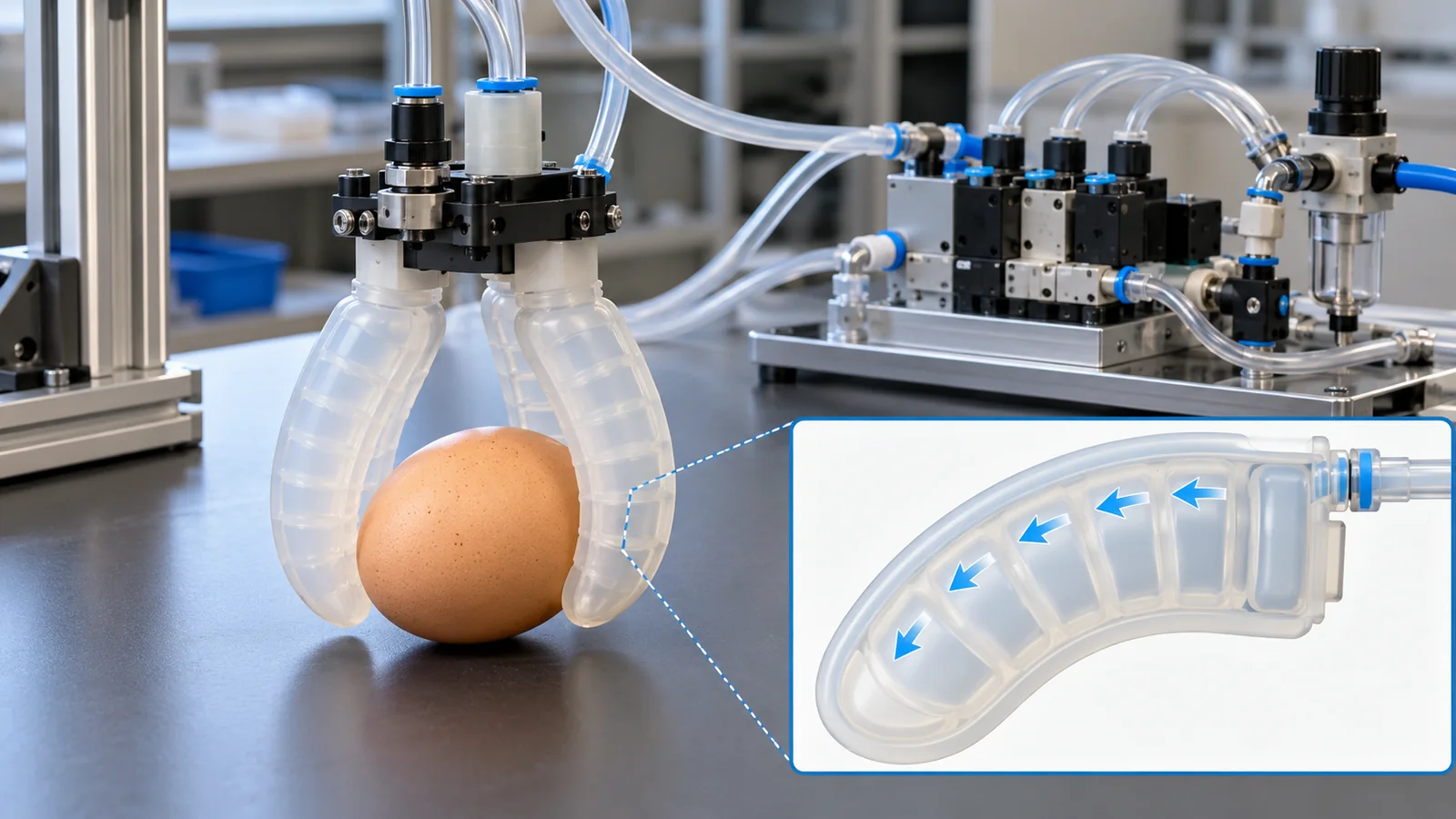
- What is a soft robot? (the short version)
- How soft is “soft”?
- Way 1: inflate it with air
- Way 2: electrically driven “oil pouches”
- A legged robot test: is the power use really small?
- Way 3: heat, living muscle and jamming
- How do you control a soft body?
- Where robots and drones could use this, and the limits
- Limits, what we could not confirm, and a summary
- How to read the yardsticks and standards
- Glossary
- References (primary sources)
- Claim-to-source audit
Sourced = stated in a published source (linked)
Our calculation = our own calculation or arrangement using published values
Not yet confirmed = plans, targets or work in progress that is not settled
Inference is shown in bold. Readings that have no source are marked “commentary”.
Values from papers are results from laboratory test rigs under stated conditions. They are not field performance. Manufacturer values are “company’s stated values” and have not been verified by a third party. We do not rank different devices or robots by their numbers. This field moves fast, so the state of papers and standards is as of the check date (25 October 2026). We give no individual medical or safety advice.
1. What is a soft robot? (the short version)
- A soft robot is a robot whose soft body deforms to make it move. The body is silicone rubber, plastic film, oil, or sometimes cultured muscle. Unlike a conventional robot built from a metal skeleton and joints, its “moving parts” and its “body” are one and the same [Ref. 1].
- There are several ways to power it, each with a different weakness. Pneumatic (needs a compressor), electrohydraulic (needs a supply of hundreds to thousands of volts), heat (slow to cool) and living muscle (needs a culture bath). All of them still have open problems outside the laboratory.
- “Soft” does not mean “safe”, “energy-saving” or “can grasp anything”. What softness buys is shape adaptation and tolerance of bumps. The price is hard control, low output and heavy power supplies.
In this series a robot is a combination of three things: “sense” (sensors), “think” (control and intelligence) and “move” (actuators). The actuator is the robot’s muscle, usually a motor plus a gear reducer. Degrees of freedom (DOF) are the number of directions in which a joint can move: an arm with six joints has six DOF. The star of this article is a robot in which “move” and “body” are merged.
Where this fits in the series: the article on soft actuators and artificial muscles covers the materials side (dielectric elastomers, IPMC, hydrogels, coiled fibers), and the article on shape memory alloys covers heat-driven metals. To avoid overlap, this article sticks to what has been achieved as a robot. Joint drives are covered in our explainer on joint actuators, hands in the one on robot hands and grasping, and touch in the one on tactile sensors and electronic skin.
First, here is how a rigid robot and a soft robot differ in four parts (Fig. 2).
Soft robots include not only lumps of rubber but also plastic-film pouches filled with oil, bags filled with granules and combinations of cultured muscle with a plastic frame. What they share is that part or all of the body deforms a lot to do work. Where “soft” begins is not settled (next chapter).
2. How soft is “soft”?
To put “soft” in numbers, people usually use the Young’s modulus, a measure of stiffness when something is pulled. But a paper that sorted out definitions of soft robots (Chubb et al., 2019) points out that the Young’s modulus ranges called “soft” differ between sources [Ref. 2] Sourced. In other words, we found no common line of the form “below this modulus, it is soft” (not confirmed). So we look at real material numbers instead.
Silicone rubbers widely used for soft-robot prototypes (Ecoflex, Dragon Skin) have their numbers in manufacturer data sheets. Figure 3 plots some of them.
How to read it: the “100% modulus” is the force per unit cross-section when the rubber is stretched to twice its length. Ecoflex 00-30, for example, is 10 psi, or about 69 kPa (0.069 MPa) Our calculation. Dragon Skin 30 is 86 psi, about 593 kPa Our calculation: stretching it to the same twofold length takes about 8.6 times the stress. Elongation at break is 900% for Ecoflex 00-30 and 364% for Dragon Skin 30 [Ref. 3, 4] Sourced. The harder the grade, the less it stretches (the arrangement is Our calculation).
In robot design, even within silicone you balance ease of bending (softer bends at lower pressure) against toughness and recovery force (harder snaps back more firmly). Shepherd et al. used Ecoflex 00-30 or 00-50 for the stretchy layer, and report that switching to the slightly stiffer Ecoflex 00-50 raised the crawling speed from 24 m/h to 92 m/h [Ref. 5] Sourced (a comparison between two conditions in the same paper).
On processing, the data sheet describes a platinum-catalyzed addition-cure silicone. It warns that cure can be inhibited by molds or contact materials such as latex, tin-cure silicone or sulfur-containing clays [Ref. 3] Sourced. This is a modest but practical point when you plan 3D-printed molds or bonding to other plastics (commentary).
The Ecoflex data sheet states hardness as “Shore 00-30” and cites ASTM D-2240 as the test method [Ref. 3] Sourced. ISO 48-4:2018, on the other hand, is the standard for measuring Shore hardness with a durometer, and its abstract lists the scales A, D, AO (for low-hardness and cellular rubbers) and AM (for thin test pieces) [Ref. 6] Sourced. Because the scale names differ, do not map a manufacturer’s notation onto an ISO scale by the printed number alone. (We did not read the ASTM standard itself; all we state is the number the data sheet cites as its hardness test.)
3. Way 1: inflate it with air
The oldest way to move a soft robot is air pressure. A handy comparison is a balloon: put air in a rubber bag and it swells; let the air out and it returns. But a balloon only swells; it does not bend. To make it bend, you attach a “hard-to-stretch layer” to one side (Fig. 4).
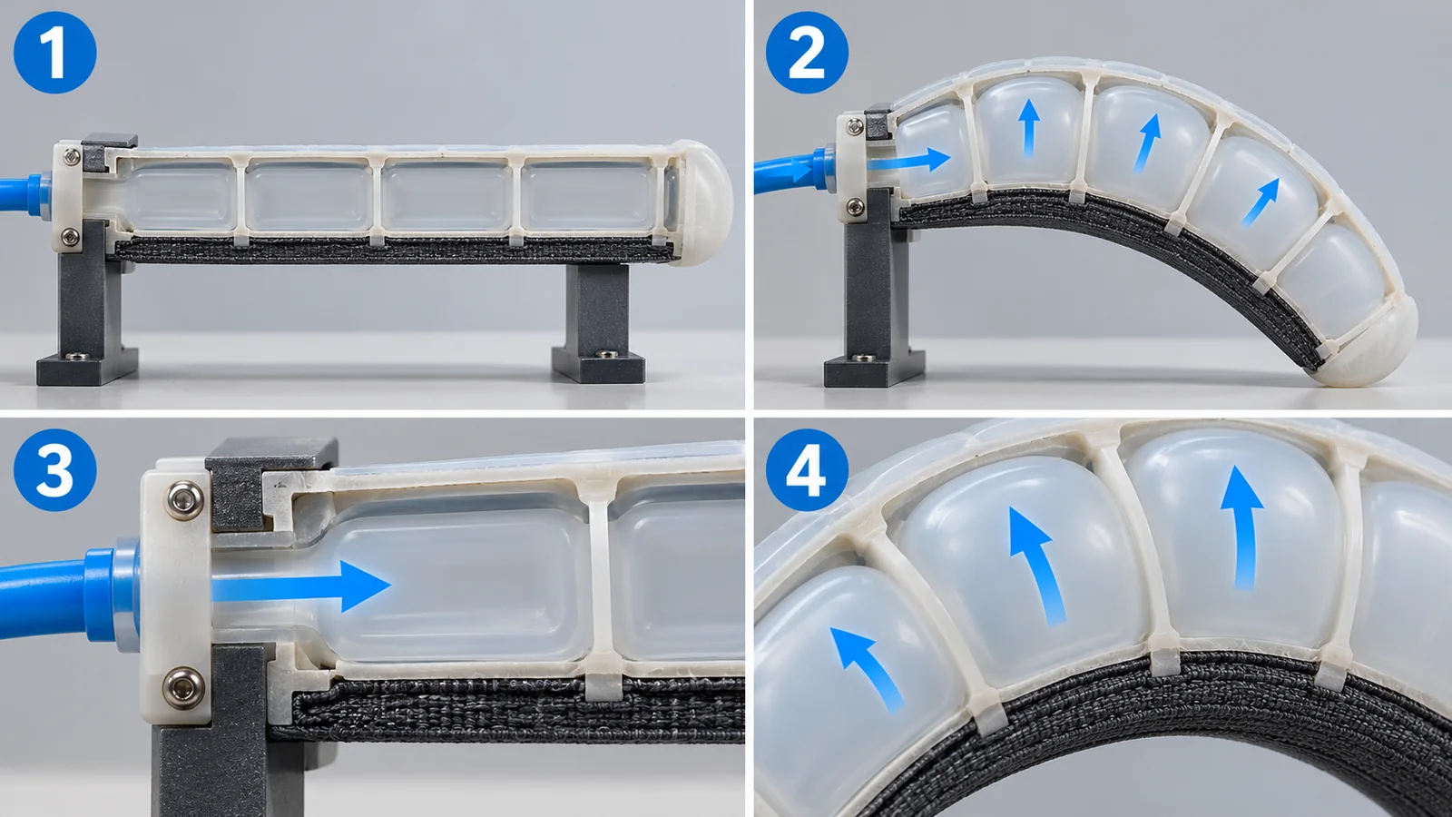
Original SVG, detailed explanation and sources
Original SVG reference: Concept diagram (vector drawing). How a pneumatic soft actuator bends: a cross-section of a stretchy layer with a row of chambers bonded to a hard-to-stretch layer. The shapes and proportions are for illustration, not those of a real device. The layer materials follow Shepherd et al. (2011) [Ref. 5].
Shepherd et al. used this approach to build a four-legged robot made entirely of elastomer (rubber). It had just five actuators and simple valves, no sensors, and ran below 10 psi [Ref. 5] Sourced. The stretchy layer is Ecoflex 00-30 or 00-50; the hard-to-stretch layer is PDMS (Sylgard 184). Molds were 3D-printed and the parts cast [Ref. 5] Sourced.
In numbers: 7 psi is about 48 kPa Our calculation (roughly half an atmosphere on top of ambient). A crawling speed of 24 +/- 3 m/h is about 6.7 mm per second Our calculation. The robot also crawled under a gap only 2.0 cm high [Ref. 5] Sourced. But it was tethered by tubing to an external compressed-air source [Ref. 5] Sourced. That points to one of the biggest open problems of the pneumatic approach: can the robot carry its own power?
There are other pneumatic examples. Hawkes et al. reported a vine-like robot that grows from its tip: pressurizing a thin-walled vessel stored inside-out lets the tip lengthen, and an asymmetry in the tip’s lengthening steers it [Ref. 7] Sourced. Wehner et al. reported a robot made only of soft materials, including its control: a microfluidic “logic circuit” autonomously regulates the decomposition of an on-board fuel, and the resulting gas inflates the pneumatic network [Ref. 8] Sourced. It shows that “completely soft, no cable” is one of the goals.
A pneumatic body is a membrane (rubber, plastic film) under constant pressure. So tear resistance, air-tightness and fatigue under repeated bending translate directly into robot lifetime (commentary). In a vine robot, where film is everted out of the tip, friction and fatigue at the folds should also matter (Inference; not confirmed in the abstract). Data on tension, fracture and gas permeability feed straight into soft-robot design.
4. Way 2: electrically driven “oil pouches” (HASEL and HALVE)
Instead of air, there is a method that uses electric force to move oil. A handy comparison is a zipper. Apply a voltage across two electrodes in a pouch and they attract each other, closing from one end like a zipper. The oil inside is squeezed out, another part of the pouch swells, and the pouch as a whole shortens (Fig. 5, left). This is called a HASEL (pronounced “hazel”; hydraulically amplified self-healing electrostatic actuator). Combining electrostatic force with oil pressure is its trademark, and in 2018 it was reported that it can repeatedly self-heal after electrical breakdown [Ref. 9] Sourced.
The “Peano-HASEL”, reported the same year, is a pouch that can be made by heat-sealing commercial plastic film, needing no frame or prestretch. The paper reports up to about 10% contraction, a strain rate of 900% per second, operation at 50 Hz and lifting more than 200 times its own weight [Ref. 10] Sourced. These are numbers from laboratory prototypes.
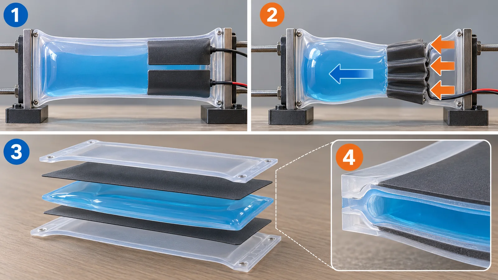
Original SVG, detailed explanation and sources
Original SVG reference: Concept diagram (vector drawing). Left: how an electrohydraulic actuator contracts. Right: layer structure of the conventional type (Peano-HASEL) and the low-voltage type (HALVE). Dimensions and permittivities follow Gravert et al. (2024) [Ref. 12]; this is not the exact structure of any real product.
The force with which the electrodes attract is small, and they move only a short distance. With oil in the pouch, the volume swept out by the closing electrodes turns into a large deformation elsewhere. This is called “hydraulic amplification”. (A comparison: squeezing a bicycle brake lever moves a part far away through a wire – except that here it is oil pressure that makes the deformation.) A second benefit is that oil flows into the spot where insulation was damaged, which makes self-healing easier (the papers’ claim [Ref. 9]).
Cutting the voltage with materials: HALVE
The weak point of HASEL is its high voltage. Gravert et al. (ETH Zurich) note that conventional electrohydraulic actuators need several thousand volts, which makes the driving electronics bulky and inefficient [Ref. 12] Sourced. They also list exposed electrodes, which make the devices hard to use near people.
Their answer is the HALVE (hydraulically amplified low-voltage electrostatic) actuator. Conventionally, a single film (such as BoPET, biaxially oriented polyester) served as both “structure” and “insulation (the capacitor’s dielectric)”. HALVE separates the two roles. A strong polymer outer shell provides structure and outer insulation, and a thin layer of a high-permittivity polymer (P(VDF-TrFE-CTFE)) earns the electrostatic force (Fig. 5, right). The paper states that replacing 15 µm of BoPET (relative permittivity 3.3) with 5 µm of P(VDF-TrFE-CTFE) (relative permittivity about 40) could in theory cut the required voltage about six-fold [Ref. 12] Sourced.
In measurements, HALVE reached an average power density of 50.5 W/kg and a peak strain rate of 971% per second at 1100 V, which the paper says is 4.9 times lower in voltage than the previous state of the art [Ref. 12] Sourced. The paper sets this beside typical mammalian skeletal muscle (about 50 W/kg and a peak of about 500% per second) [Ref. 12] Sourced. It also showed devices that are safe to touch, waterproof and “self-clearing” (when insulation fails, the electrode is destroyed locally and the short circuit clears) [Ref. 12] Sourced. The power electronics were also made compact: a 28 cm robotic fish carried them and swam untethered. Its speed, however, was at most 3.8 cm/s (0.14 body lengths per second) at 2 Hz, the average power draw was 0.6 W, and one battery charge lasted about 54 minutes of continuous actuation [Ref. 12] Sourced.
The paper lists its own challenges [Ref. 12] Sourced. (1) The dielectric strength of the thin P(VDF-TrFE-CTFE) layer is cited in the literature as up to about 350 V/µm, but in the devices made, breakdown occurred regularly above about 120 V/µm; the authors suggest defects and impurities from fabrication outside a clean room. (2) The durability of the heat seals is a problem. (3) The force density is lower than the conventional type: above 6 kV, the conventional BoPET type (industrial film that withstands more than 300 V/µm) did better in force-strain behavior.
This is a trade-off between “lowering the voltage” and “gaining force”. A material that combines high permittivity with high dielectric strength – in practice, thin-film forming, defect control and sealing technology – sets the ceiling on performance (commentary). By the way, the Ecoflex data sheet gives a dielectric strength of “>350 volts/mil”, which is about 14 V/µm Our calculation. The test method and thickness differ, so we do not rank them, but it shows that one reason plastic films are chosen for electrohydraulics is an order-of-magnitude difference in insulation (commentary).
More detail: how much does the force change if you halve the voltage?
Electrostatic force is proportional to the square of the electric field (Maxwell stress). For the same geometry the field is proportional to voltage, so halving the voltage cuts the force to about one quarter Our calculation. For HALVE to cut the voltage and keep the force, a material with high relative permittivity must draw a large force from the same voltage (the “about six-fold” estimate above rests on this idea). This explanation is ours, not a derivation from the paper’s equations.
5. A legged robot test: is the power use really small?
An example that tested whether an artificial muscle works as a robot’s power source is the electrohydraulic musculoskeletal leg (PELE) of Buchner et al. It was a joint effort of the Soft Robotics Lab at ETH Zurich and the Max Planck Institute for Intelligent Systems, among others, published in Nature Communications in 2024 [Ref. 13] Sourced. It is a carbon-fiber skeleton with 3D-printed joints and an antagonistic (pulling-in-opposite-directions) pair of electrohydraulic muscles. The muscles are stacks of Peano-HASEL connected to the joints by tendons [Ref. 13] Sourced.
The main results are as follows [Ref. 13] Sourced.
- Gait motions above 5 Hz and high jumps up to 40% of the leg height (highest 128 mm)
- Hopping over grass, sand, gravel, pebbles and large rocks using open-loop force control only (control that does not measure and correct for the ground)
- Self-sensing of obstacles from the change in the muscles’ capacitance
- A minimum net cost of transport (COT), a measure of movement efficiency, of 0.73 (at a robot mass of 225 g)
COT is the energy needed to move a given weight a given distance, divided by the work of gravity on it (E / mgl), a dimensionless number. For a 225 g robot at 0.73, moving 1 m takes about 1.6 J Our calculation (0.73 x 0.225 kg x 9.81 m/s² x 1 m). The paper states that this value excludes the loss in high-voltage conversion (typically about 75% efficient) [Ref. 13] Sourced. Assuming 75% would give about 2.1 J/m Our calculation, but that is our own estimate under our assumption, not a value in the paper.
The paper also compared PELE with a direct-drive motor leg of the same size and mass. During squatting the average power was 25.3 W for the motor leg and 306 mW for PELE (1.2% of the motor leg). Just holding a posture took 17 W for the motor leg and 9.4 mW for PELE (Fig. 6) [Ref. 13] Sourced. As a ratio, that is about 1 to 1800 Our calculation.
This comparison covers squatting and holding only. The authors themselves write that the comparison leg was direct-drive and that a state-of-the-art motor leg with a transmission may be more efficient. The efficiency of continuous fast motion such as running has not been tested. In addition, the leg was tethered to a stationary supply able to deliver -10 kV to +10 kV at 50 W or more, and the experiment used a single two-degree-of-freedom leg mounted on a boom [Ref. 13] Sourced. The correct reading: “low power use was shown for producing force while stationary”. The battery life of a whole mobile robot, including the weight of the power supply, is a separate challenge.
The leg’s voltage-force relationship also needs care. The paper notes a dead zone of 0 to 3 kV (depending on the external load) in which the muscles do not respond to voltage [Ref. 13] Sourced. The controller overlaps extensor and flexor activation to compensate. Even a body that is comparatively soft has awkward behavior in its drive, such as a range where voltage does nothing.
6. Way 3: heat, living muscle and jamming
Besides pneumatic and electrohydraulic drives, three other means of power or function often come up. Figure 7 lines up the five methods by “power in”, “example” and “limit” – our own arrangement.
Heat-driven systems (overview)
Shape memory alloys and coiled fibers contract when warmed by an electric current. They give a large force from a small volume, but they take time to cool, so motion tends to be slow. Details are in our explainers on shape memory alloys and on soft actuators and artificial muscles.
Moving with living muscle (biohybrid)
Another approach uses real cultured muscle as the power source. In 2018 a University of Tokyo group reported a robot whose joint was moved by an antagonistic pair of skeletal muscle tissues. The joint turned about 90 degrees, the lifetime was about one week, and it could pick and place objects [Ref. 14] Sourced. In 2025 the group reported a hand with fingers powered by bundles of muscle tissue (MuMuTA). One bundle produced a contractile force of about 8 mN over a contractile length of about 4 mm, and cables turned that into bending of multi-jointed fingers [Ref. 15] Sourced. 8 mN corresponds to the weight of about 0.8 g Our calculation.
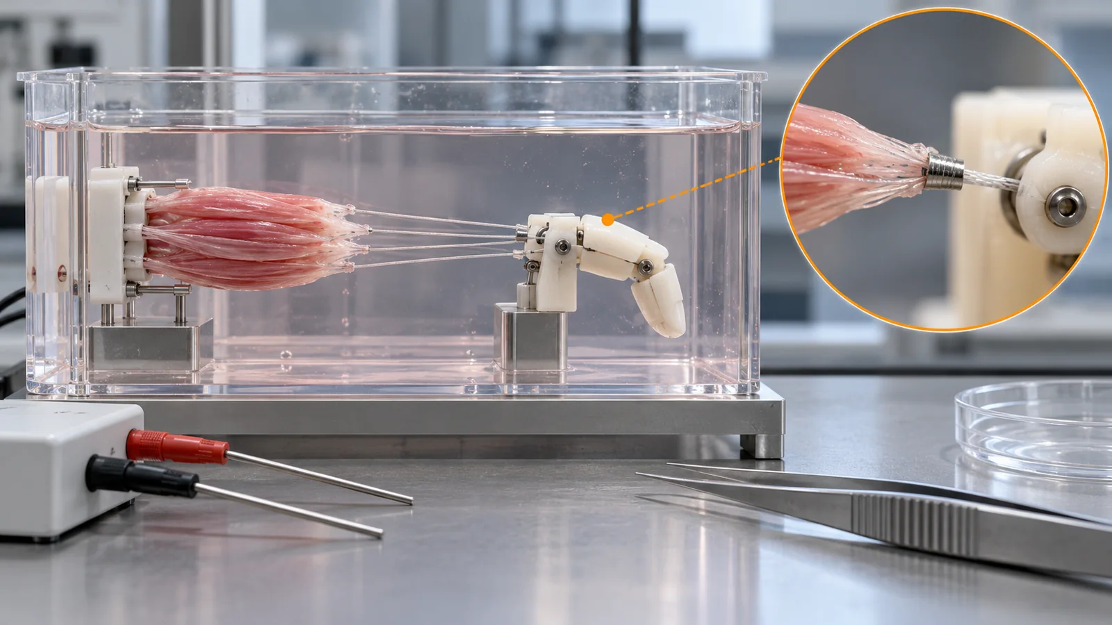
The reports so far show small forces for short periods in a culture bath [Ref. 14, 15]. The attractions – flexibility, self-repair, low energy use – are real, but from the sources we checked we cannot tell whether such muscle could power industrial or outdoor robots (not confirmed). The research also has a purpose in understanding and reproducing how living systems work (the papers’ stated motivation).
Switching stiffness: jamming
The last method is not about “moving” but about “switching stiffness”. Brown et al. reported a gripper made from a thin rubber bag filled with powder (ground coffee). Press the bag onto an object and the powder flows around its shape. Pump the air out (a pressure difference of about 75 kPa) and the grains lock together and harden, so the bag can lift the object while wrapped around it [Ref. 16] Sourced. The membrane is latex rubber 0.3 mm thick. For many items (light bulbs, LEDs, bottle caps, tubing and others) the pick-up success rate over 10 trials each was 100%. The objects it could not grip were those the bag cannot wrap around the sides of: large hemispheres, thin disks lying flat, and very soft items such as cotton balls [Ref. 16] Sourced.
7. How do you control a soft body?
The other wall for soft robots is control. For a rigid arm, measuring the joint angles fixes the pose. A soft body bends continuously, and the quantities describing “where and how much it is bent” are in principle very many (Fig. 9, top). In a survey, Della Santina, Duriez and Rus define continuum soft robots as “mechanical systems entirely made of continuously deformable elements” and say that what characterizes the class is continuum (or multi-body) dynamics, a non-negligible elastic potential field, and uncertainty in sensing and actuation [Ref. 17] Sourced.
So how is it handled? There are roughly three ideas. (1) Compute with a model: predict the body’s shape and force from a continuum-mechanics model and use it. The survey covers both the systematic overview and the open problems [Ref. 17] Sourced. (2) Use classical control at the low level: in PELE, target tendon positions come from inverse kinematics (a calculation that works backward from a target tip position to the joint angles), and muscle force is adjusted by PID control [Ref. 13] Sourced. (3) Let the softness of the body do some of the work: with pairs of antagonistic muscles, adjust stiffness and let the body absorb the ground’s shape. PELE hopped over grass, sand and stones with no elaborate correction [Ref. 13] Sourced.
Idea (3) does not mean control is unnecessary. Even in PELE, the voltage patterns to the muscles are designed, dead-zone compensation is used, and obstacle detection and avoidance are switched using self-sensing anomaly detection [Ref. 13] Sourced. The softness of the body takes over part of the control burden – sometimes described as “letting the body do the computing” (commentary). A safe understanding is that, in particular situations, measurement can be reduced but never reaches zero.
8. Where robots and drones could use this, and the limits
Here is a summary from the standpoint of robots and drones. Examples of soft mechanisms mounted on drones were not covered by the sources we checked (not confirmed). The readings below are our commentary.
| Strengths (confirmed in papers) | Costs and limits (confirmed in papers) | Materials and parts angle (commentary) |
|---|---|---|
| Shape-adapting grasp (jamming: success on many items, 10 trials each) [16] Sourced | Cannot grip shapes it cannot wrap around the sides of; needs a pump [16] Sourced | Membrane thickness, friction, durability; granule size and density |
| Complex motion from simple air pressure (five actuators, no sensors) [5] Sourced | Was tethered to a compressed-air source [5] Sourced | Silicone hardness, membrane air-tightness, cure inhibition at molds |
| Electrohydraulic leg with low power use at rest (about 1.2% of the motor leg) [13] Sourced | Stationary high-voltage supply; one leg on a boom arm [13] Sourced | Dielectric permittivity and breakdown, film sealing |
| Lower voltage (1100 V), safe to touch, waterproof [12] Sourced | Lower force density; breakdown near 120 V/µm from thin-film defects [12] Sourced | Thin-film forming, defect control, heat-seal durability |
| Living-muscle joints and fingers (a bundle of about 8 mN) [14, 15] Sourced | Needs a culture bath; lifetime about one week (2018 example) [14] Sourced | Bonding living tissue to a plastic frame; materials in culture fluid |
The facts in each row are as stated in the bracketed references. The arrangement of the table is Our calculation. The right-hand column is our commentary (readings without a source).
Softness is one factor that softens an impact, but safety depends on several things: speed, mass, contact area, pressure and, here, voltage. Buchner et al. list exposed electrodes at high voltage as a challenge and write that outside the lab additional safety measures (such as fault detection and fast shutoff) would be needed [Ref. 13] Sourced. And ISO/TS 15066:2016, the technical specification on collaborative-robot safety, applies to industrial robot systems and not to non-industrial robots (though its principles may be useful elsewhere, it says) [Ref. 18] Sourced. The correct reading: “being soft” and “being recognized as safe under a standard” are different matters.
Looking back over this article’s examples, what set performance was choice of materials more than machine design: the hardness and stretch of the silicone (Fig. 3), the combination of oil, plastic film and high-permittivity polymer (Fig. 5), film thickness and dielectric strength, heat-seal durability. These are areas where materials engineers can contribute directly. The weakness is that evaluation methods are not yet in place. How performance is measured differs from paper to paper, and we could not find a standard aimed directly at artificial muscles or soft robots (see the later chapters). There is room for materials people to propose reproducible evaluation methods (Inference).
9. Limits, what we could not confirm, and a summary
What we could not confirm
- A common Young’s-modulus definition of “soft”: we confirmed that ranges differ between sources, but found no common line [Ref. 2]
- Examples on drones: we did not confirm specific reports of drones carrying soft grippers or legs
- Lifetime and reliability for industrial or outdoor use: our examples are laboratory experiments, and we found no multi-year durability data
- Standards aimed directly at artificial muscles or soft robots: a search of ISO standards for “soft robot” and “artificial muscle” turned up none that we could confirm (related general standards are in Chapter 10)
- Full texts of some papers: the Rus and Tolley review (Nature) and the papers by Wehner et al. and Hawkes et al. were checked at the abstract level; we state no numbers from their main text
- ASTM standards: ASTM International’s site states that it prohibits AI use, so we did not open it. We state only the fact of the numbers the manufacturer’s data sheet cites
Summary
- A soft robot is one whose “moving parts” and “body” are merged. Softness is read from per-material data sheets (Fig. 3) Our calculation
- There are five ways to move one. Pneumatic is simple and has a long history but tends to be tethered to its power source. Electrohydraulic has shown muscle-like output but needs high-voltage supplies. Heat, living muscle and jamming each have other limits (Fig. 7)
- HALVE cut the voltage about 4.9-fold through a materials idea (a high-permittivity polymer). Force density and thin-film defects remain challenges Sourced
- An electrohydraulic leg showed low power use at rest. But the comparison partner and conditions are limited, so “more efficient than motors” cannot be concluded (Fig. 6)
- Controlling a soft body is hard; combinations of classical control and the body’s softness are being tried (Fig. 9)
10. How to read the yardsticks and standards
A soft robot’s performance can be sorted into three groups of yardsticks: material yardsticks (hardness, tension, dielectric breakdown), actuator yardsticks (power density, strain rate, lifetime) and robot yardsticks (cost of transport, grasp success rate, power use). For every yardstick you must check what it is divided by and under what conditions it was measured, or the numbers cannot be compared. “50 W/kg”, for example, means different things depending on whether the mass is that of the muscle or of the whole device. The table lists what we could confirm (checked 25 October 2026).
| What is evaluated | Representative test or benchmark (name, source) | Standard, regulation or guideline (ISO, NIST, etc.) | Cautions in reading |
|---|---|---|---|
| Rubber hardness | Manufacturer data sheets (Shore 00, A and so on) [3, 4] Sourced | ISO 48-4:2018 “Rubber, vulcanized or thermoplastic – Determination of hardness – Part 4: Indentation hardness by durometer method (Shore hardness)” (published August 2018, confirmed in 2024) [6] Sourced | Do not map scales with different names (00, A, AO) onto each other by number alone |
| Rubber tension and stretch | Data-sheet 100% modulus and elongation at break [3, 4] Sourced | ISO 37:2024 “Rubber, vulcanized or thermoplastic – Determination of tensile stress-strain properties” (7th edition, May 2024) [11] Sourced | Values change with specimen shape and speed. Do not compare one maker’s stated values with another’s |
| Artificial-muscle output, strain rate, lifetime | Measurements in each paper (Peano-HASEL [10], HALVE [12]). The denominator (muscle only or whole device) and conditions differ between papers Sourced | Not confirmed | Check on which yardstick “muscle-like” actually matches |
| Locomotion efficiency | Net cost of transport COT = E / mgl (Buchner et al.) [13] Sourced | Not confirmed | Meaning changes with whether power-supply losses are included and whether the supply is stationary |
| Grasp success rate | Trials and success rate per item (Brown et al.: 10 each) [16] Sourced. A shared object set, YCB [22]; NIST SP 1227 (metrics and test methods for robotic hands, a draft of October 2018) [21] Sourced Not yet confirmed | NIST SP 1227 is a draft. We could not confirm a final version | Success rate depends on the set of objects tried. Read it with objects of different softness and shape included |
| Terminology | – | ISO 8373:2021 “Robotics – Vocabulary” (3rd edition, November 2021; a revision, ISO/DIS 8373, is in preparation) [19] Sourced Not yet confirmed | We did not check whether this standard defines “soft robot” |
| Collaborative work and safety near people | – | ISO/TS 15066:2016 “Robots and robotic devices – Collaborative robots” (covers industrial robot systems; confirmed in 2022; a successor, ISO/AWI 15066-1, is in preparation) [18] Sourced Not yet confirmed. ISO 10218-1:2025 (industrial robots) [20]. ISO 13482:2014 (personal care robots; flying robots excluded) [23] Sourced | None of them is aimed at soft robots. We did not read the standard texts |
| Safety of high-voltage parts | Buchner et al. state that additional safety measures are needed [13] Sourced | Not confirmed | Do not generalize to “safe if the current is low” |
Numbers, titles and status of standards were checked on the official ISO pages (25 October 2026). The texts are paid, so we stay with the scope statements. The arrangement of the table is Our calculation.
Cautions in reading (for materials engineers)
- A demonstration, a benchmark and the field are different things: a leg hopping over grass is the result of one leg in a lab. It is not the same as long-duration operation or safety certification of a robot
- A manufacturer’s stated value and independent verification are different: data-sheet values are manufacturer-stated and conditional. It is worth re-measuring with your own samples and conditions
- Standards are mostly voluntary: ISO standards generally become binding only when cited in law or contract (commentary). When you see “complies with a standard”, check which standard and which requirement
- Plans and achievements are different: standards under revision (ISO 8373, the successor to ISO/TS 15066) may change in content Not yet confirmed
11. Glossary
- Soft robot
- A robot whose soft body deforms to move. The “moving parts” and the “body” are one.
- Actuator
- The robot’s muscle: the part that produces force or motion.
- Degrees of freedom (DOF)
- The number of directions in which a joint can move.
- Young’s modulus
- A measure of stiffness when pulled. Larger means stiffer.
- 100% modulus
- The stress needed to stretch rubber to twice its length. A guide to softness.
- Shore hardness
- Indentation hardness of rubber measured with a durometer. Several scales exist (A, D, 00 and others).
- Addition-cure silicone
- Silicone that cures with a platinum catalyst. Cure can be inhibited by some contact materials.
- PDMS
- Polydimethylsiloxane, a typical silicone, often used for soft-robot prototypes.
- Pneu-net
- A rubber actuator with a row of small chambers that bends under air pressure.
- HASEL
- Hydraulically amplified self-healing electrostatic actuator: an oil-filled pouch that contracts under electric force.
- Peano-HASEL
- A HASEL made by heat-sealing plastic film that contracts in a straight line.
- HALVE
- A low-voltage electrohydraulic actuator that uses a high-permittivity polymer to cut the voltage.
- BoPET
- Biaxially oriented polyester film, used for HASEL pouches.
- Relative permittivity
- A material property for storing electric charge. Larger stores more at the same voltage.
- Dielectric strength
- The electric field at which an insulator fails and current flows (V/µm and so on).
- Antagonistic muscles
- A pair of muscles that pull in opposite directions on a joint.
- Open-loop control
- Control that does not measure the result and correct. It just plays out a set pattern.
- PID control
- Classical control that corrects the error using its present value, its accumulation and its rate of change.
- Inverse kinematics
- Calculating joint angles backward from a target tip position.
- Cost of transport (COT)
- Energy per unit weight per unit distance. Smaller is more efficient.
- Jamming
- Hardening a bag of granules by pumping out the air, to switch its stiffness.
- Biohybrid
- A robot combining cultured living tissue (such as muscle) with artificial parts.
12. References (primary sources)
- Rus D., Tolley M. T. “Design, fabrication and control of soft robots”, Nature 521, 467-475 (2015), DOI 10.1038/nature14543 (checked at abstract level) – https://doi.org/10.1038/nature14543
- Chubb O. et al. “Towards an ontology for soft robots: what is soft?”, Bioinspiration & Biomimetics 14, 063001 (2019), DOI 10.1088/1748-3190/ab483f (checked at abstract level) – https://doi.org/10.1088/1748-3190/ab483f
- Smooth-On “Ecoflex Series Technical Bulletin” (silicone data sheet, version code 011124DH) – https://www.smooth-on.com/tb/files/ECOFLEX_SERIES_TB.pdf
- Smooth-On “Dragon Skin Series Technical Bulletin” (silicone data sheet, version code 040825PA) – https://www.smooth-on.com/tb/files/DRAGON_SKIN_SERIES_TB.pdf
- Shepherd R. F. et al. “Multigait soft robot”, PNAS 108, 20400-20403 (2011), DOI 10.1073/pnas.1116564108 (main text checked) – https://pmc.ncbi.nlm.nih.gov/articles/PMC3251082/
- ISO “ISO 48-4:2018 Rubber, vulcanized or thermoplastic – Determination of hardness – Part 4: Indentation hardness by durometer method (Shore hardness)” (ISO standard page) – https://www.iso.org/standard/74969.html
- Hawkes E. W. et al. “A soft robot that navigates its environment through growth”, Science Robotics 2, eaan3028 (2017), DOI 10.1126/scirobotics.aan3028 (checked at abstract level) – https://doi.org/10.1126/scirobotics.aan3028
- Wehner M. et al. “An integrated design and fabrication strategy for entirely soft, autonomous robots”, Nature 536, 451-455 (2016), DOI 10.1038/nature19100 (checked at abstract level) – https://doi.org/10.1038/nature19100
- Acome E. et al. “Hydraulically amplified self-healing electrostatic actuators with muscle-like performance”, Science 359, 61-65 (2018), DOI 10.1126/science.aao6139 (checked at abstract level) – https://doi.org/10.1126/science.aao6139
- Kellaris N. et al. “Peano-HASEL actuators: Muscle-mimetic, electrohydraulic transducers that linearly contract on activation”, Science Robotics 3, eaar3276 (2018), DOI 10.1126/scirobotics.aar3276 (checked at abstract level) – https://doi.org/10.1126/scirobotics.aar3276
- ISO “ISO 37:2024 Rubber, vulcanized or thermoplastic – Determination of tensile stress-strain properties” (ISO standard page) – https://www.iso.org/standard/86892.html
- Gravert S.-D. et al. “Low-voltage electrohydraulic actuators for untethered robotics”, Science Advances 10, eadi9319 (2024), DOI 10.1126/sciadv.adi9319 (open access; main text checked) – https://pmc.ncbi.nlm.nih.gov/articles/PMC10775996/
- Buchner T. J. K. et al. “Electrohydraulic musculoskeletal robotic leg for agile, adaptive, yet energy-efficient locomotion”, Nature Communications 15, 7634 (2024), DOI 10.1038/s41467-024-51568-3 (open access; main text checked) – https://doi.org/10.1038/s41467-024-51568-3
- Morimoto Y. et al. “Biohybrid robot powered by an antagonistic pair of skeletal muscle tissues”, Science Robotics 3, eaat4440 (2018), DOI 10.1126/scirobotics.aat4440 (checked at abstract level) – https://doi.org/10.1126/scirobotics.aat4440
- Ren Z. et al. “Biohybrid hand actuated by multiple human muscle tissues”, Science Robotics 10, eadr5512 (2025), DOI 10.1126/scirobotics.adr5512 (checked at abstract level) – https://doi.org/10.1126/scirobotics.adr5512
- Brown E. et al. “Universal robotic gripper based on the jamming of granular material”, PNAS 107, 18809-18814 (2010), DOI 10.1073/pnas.1003250107 (main text checked) – https://pmc.ncbi.nlm.nih.gov/articles/PMC2973877/
- Della Santina C., Duriez C., Rus D. “Model-Based Control of Soft Robots: A Survey of the State of the Art and Open Challenges”, IEEE Control Systems 43(3), 30-65 (2023) (arXiv:2110.01358; checked at abstract level) – https://arxiv.org/abs/2110.01358
- ISO “ISO/TS 15066:2016 Robots and robotic devices – Collaborative robots” (ISO standard page) – https://www.iso.org/standard/62996.html
- ISO “ISO 8373:2021 Robotics – Vocabulary” (ISO standard page) – https://www.iso.org/standard/75539.html
- ISO “ISO 10218-1:2025 Robotics – Safety requirements – Part 1: Industrial robots” (ISO standard page) – https://www.iso.org/standard/73933.html
- Falco J., Van Wyk K., Messina E. “Performance Metrics and Test Methods for Robotic Hands”, NIST Draft Special Publication 1227 (October 2018, draft) – https://doi.org/10.6028/NIST.SP.1227-draft
- Calli B. et al. “Benchmarking in Manipulation Research: The YCB Object and Model Set and Benchmarking Protocols”, IEEE Robotics & Automation Magazine 22(3), 36-52 (2015) (arXiv:1502.03143) – https://arxiv.org/abs/1502.03143
- ISO “ISO 13482:2014 Robots and robotic devices – Safety requirements for personal care robots” (ISO standard page) – https://www.iso.org/standard/53820.html
13. Claim-to-source audit
| Claim in the text | Basis | Category |
|---|---|---|
| The Young’s modulus ranges called “soft” differ between sources; definitions of soft robots are diverse (Chubb et al., 2019) | Chubb O. et al. Reference 1 https://doi.org/10.1088/1748-3190/ab483f | Sourced |
| Soft robots have soft-material bodies, in contrast to robots built from rigid materials (abstract of the Rus and Tolley review) | Rus D., Tolley M. T. Reference 1 https://doi.org/10.1038/nature14543 | Sourced |
| Ecoflex 00-10/00-30/00-50 hardness notation, 100% modulus 8/10/12 psi, elongation at break 800/900/980%, platinum-cure addition silicone, cure-inhibition warning, dielectric strength >350 V/mil, values after 7 days at 23 °C | Smooth-On Reference 1 https://www.smooth-on.com/tb/files/ECOFLEX_SERIES_TB.pdf | Sourced |
| Dragon Skin 10/20/30 100% modulus 22/49/86 psi and elongation at break 1000/620/364% (values after 7 days at 23 °C) | Smooth-On Reference 1 https://www.smooth-on.com/tb/files/DRAGON_SKIN_SERIES_TB.pdf | Sourced |
| About 69 kPa for Ecoflex 00-30, about 593 kPa for Dragon Skin 30, the 8.6x ratio, and conversion of 350 V/mil to about 14 V/µm | Our calculation (inputs are published values from the sources) Reference 1 https://www.smooth-on.com/tb/files/ECOFLEX_SERIES_TB.pdf Reference 2 https://www.smooth-on.com/tb/files/DRAGON_SKIN_SERIES_TB.pdf | Our calculation |
| Title of ISO 48-4:2018 and the scales A, D, AO and AM (published August 2018, confirmed in 2024) | ISO Reference 1 https://www.iso.org/standard/74969.html | Sourced |
| Title of ISO 37:2024 (7th edition, May 2024) and that it determines tensile strength, elongation at break and so on | ISO Reference 1 https://www.iso.org/standard/86892.html | Sourced |
| Four-legged soft robot: entirely elastomer, five actuators, no sensors, below 10 psi, Ecoflex 00-30/00-50 and PDMS (Sylgard 184) layers, casting, tethered by tube to an external compressed-air source (7 psi), crawls under a 2.0 cm gap | Shepherd R. F. et al. Reference 1 https://pmc.ncbi.nlm.nih.gov/articles/PMC3251082/ | Sourced |
| Crawling speed 24 +/- 3 m/h, and 92 +/- 4.3 m/h with Ecoflex 00-50 | Shepherd R. F. et al. Reference 1 https://pmc.ncbi.nlm.nih.gov/articles/PMC3251082/ | Sourced |
| Conversion of 7 psi to about 48 kPa and 24 m/h to about 6.7 mm/s | Our calculation (inputs are published values from the sources) Reference 1 https://pmc.ncbi.nlm.nih.gov/articles/PMC3251082/ | Our calculation |
| A vine-like robot that grows from its tip and steers by asymmetric lengthening (abstract of Hawkes et al., 2017) | Hawkes E. W. et al. Reference 1 https://doi.org/10.1126/scirobotics.aan3028 | Sourced |
| A robot of soft materials driven by gas from fuel decomposition (abstract of Wehner et al., 2016) | Wehner M. et al. Reference 1 https://doi.org/10.1038/nature19100 | Sourced |
| HASEL couples electrostatic and hydraulic forces and can self-heal repeatedly after dielectric breakdown (abstract of Acome et al., 2018) | Acome E. et al. Reference 1 https://doi.org/10.1126/science.aao6139 | Sourced |
| Peano-HASEL: made by heat-sealing commercial materials, no frame or prestretch, up to about 10% contraction, 900% per second, 50 Hz, lifts more than 200 times its weight | Kellaris N. et al. Reference 1 https://doi.org/10.1126/scirobotics.aar3276 | Sourced |
| HALVE: conventional electrohydraulic actuators need thousands of volts, exposed electrodes are a safety concern, 15 µm BoPET (permittivity 3.3) replaced by 5 µm P(VDF-TrFE-CTFE) (permittivity 40) gives about six-fold lower voltage in theory, 1100 V, average power density 50.5 W/kg, peak strain rate 971% per second, 4.9x lower voltage, safe to touch, waterproof, self-clearing | Gravert S.-D. et al. Reference 1 https://pmc.ncbi.nlm.nih.gov/articles/PMC10775996/ | Sourced |
| HALVE robotic fish: 28 cm long, up to 3.8 cm/s (0.14 body lengths per second at 2 Hz), 0.6 W average, about 54 min | Gravert S.-D. et al. Reference 1 https://pmc.ncbi.nlm.nih.gov/articles/PMC10775996/ | Sourced |
| HALVE challenges: breakdown near 120 V/µm (up to 350 V/µm in the literature), heat-seal durability, low force density, BoPET type better above 6 kV | Gravert S.-D. et al. Reference 1 https://pmc.ncbi.nlm.nih.gov/articles/PMC10775996/ | Sourced |
| A halved voltage gives about one quarter of the force (electrostatic force is proportional to the square of the field) | Commentary (reading not found in a source); our own organization, not the view of any institution | Commentary |
| PELE structure (carbon-fiber skeleton, 3D-printed joints, antagonistic Peano-HASEL muscle packs, tendons), motion above 5 Hz, 40% of leg height, highest jump 128 mm, open-loop hopping over grass, sand, gravel, pebbles and large rocks, capacitive self-sensing | Buchner T. J. K. et al. Reference 1 https://doi.org/10.1038/s41467-024-51568-3 | Sourced |
| PELE: minimum net COT 0.73 (225 g), excludes high-voltage conversion loss (about 75%), comparison with the motor leg (25.3 W vs 306 mW, 17 W vs 9.4 mW), dead zone 0 to 3 kV, PID and inverse kinematics, limitations (stationary supply, -10 kV to 10 kV at 50 W or more, one 2-DOF leg, boom arm, exposed electrodes) | Buchner T. J. K. et al. Reference 1 https://doi.org/10.1038/s41467-024-51568-3 | Sourced |
| COT 0.73 x 0.225 kg x 9.81 x 1 m is about 1.6 J, about 2.1 J/m if 75% is assumed, 306 mW is about 1.2% of 25.3 W, and 9.4 mW vs 17 W is about 1 to 1800 | Our calculation (inputs are published values from the sources) Reference 1 https://doi.org/10.1038/s41467-024-51568-3 | Our calculation |
| Muscle-tissue robot (antagonistic pair of skeletal muscles, about 90 degrees, lifetime about one week, pick and place) | Morimoto Y. et al. Reference 1 https://doi.org/10.1126/scirobotics.aat4440 | Sourced |
| Muscle-tissue bundles (MuMuTA): about 8 mN, about 4 mm, cable-driven multi-jointed fingers | Ren Z. et al. Reference 1 https://doi.org/10.1126/scirobotics.adr5512 | Sourced |
| 8 mN corresponds to the weight of about 0.8 g | Our calculation (inputs are published values from the sources) Reference 1 https://doi.org/10.1126/scirobotics.adr5512 | Our calculation |
| Jamming: latex bag (0.3 mm) of ground coffee, pressure difference about 75 kPa, 100% success on many items over 10 trials each, objects it could not grip (large hemispheres, thin disks, cotton balls) | Brown E. et al. Reference 1 https://pmc.ncbi.nlm.nih.gov/articles/PMC2973877/ | Sourced |
| Definition of continuum soft robots; continuum dynamics, non-negligible elastic potential, uncertainty in sensing and actuation; open challenges (Della Santina et al.) | Della Santina C., Duriez C., Rus D. Reference 1 https://arxiv.org/abs/2110.01358 | Sourced |
| ISO/TS 15066:2016: covers industrial robot systems, not non-industrial robots, confirmed in 2022, successor ISO/AWI 15066-1 in preparation | ISO Reference 1 https://www.iso.org/standard/62996.html | Sourced |
| ISO 8373:2021: 3rd edition, November 2021, revision ISO/DIS 8373 in preparation | ISO Reference 1 https://www.iso.org/standard/75539.html | Sourced |
| Title of ISO 10218-1:2025 (safety requirements for industrial robots, 3rd edition) | ISO Reference 1 https://www.iso.org/standard/73933.html | Sourced |
| NIST SP 1227 draft (metrics and test methods for robotic hands, October 2018) | Falco J., Van Wyk K., Messina E. Reference 1 https://doi.org/10.6028/NIST.SP.1227-draft | Sourced |
| The YCB object set and benchmarking protocols | Calli B. et al. Reference 1 https://arxiv.org/abs/1502.03143 | Sourced |
| ISO 13482:2014: safety of personal care robots, excludes flying robots, confirmed in 2020 | ISO Reference 1 https://www.iso.org/standard/53820.html | Sourced |
| Nature of the figures: Figures 2 to 7 and 9 are concept diagrams or charts with our calculation made for explanation; Figures 1 and 8 are frames for AI-generated images | Commentary (reading not found in a source); our own organization, not the view of any institution | Commentary |
| The balance of hardness and stretch in design, membrane fatigue, how to view mounting on drones, and the room for materials people to propose evaluation methods | Commentary (reading not found in a source); our own organization, not the view of any institution | Commentary |
| A common modulus definition, examples on drones, long-term durability, standards aimed directly at soft robots, and main-text numbers of papers checked only at abstract level | Could not be confirmed in primary sources within the scope of this article, so it is not stated | Commentary |
Last updated: 25 October 2026 / Sources are limited to primary sources (peer-reviewed papers, official ISO and NIST pages, manufacturer data sheets). Numbers are published values from papers and data sheets, under differing conditions. A common Young’s-modulus definition of “soft”, examples on drones, long-term industrial durability and standards aimed directly at soft robots could not be confirmed, so they are not stated. Figures 2 to 7 and 9 are concept diagrams or charts with our calculation made for explanation; Figures 1 and 8 are frames for AI-generated images (no image placed yet).