TECHNOLOGY EXPLAINER
Tactile Sensors and Electronic Skin
— Methods and materials of the robot’s “skin” that senses pressure, shear and temperature, and its challenges
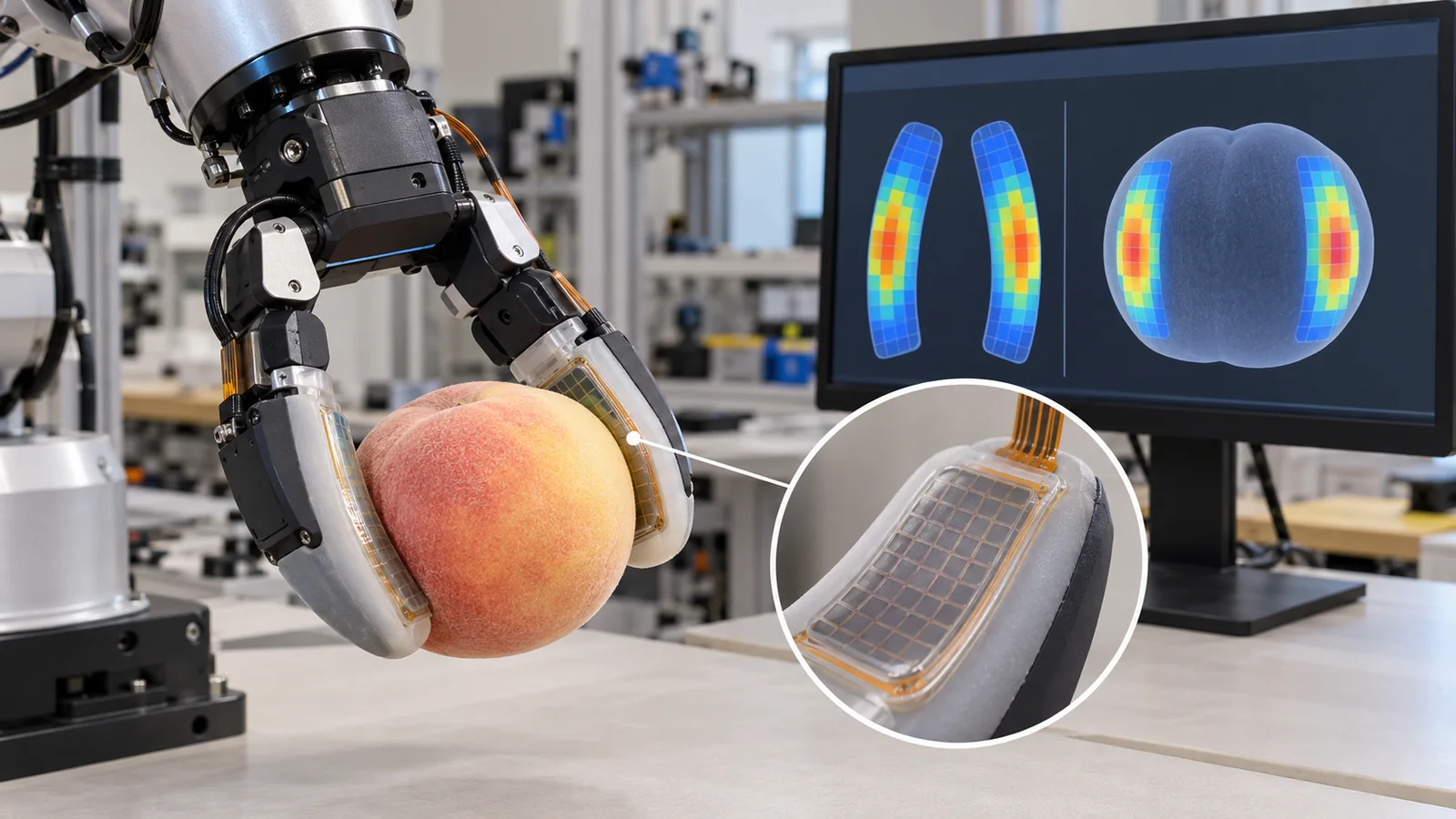
What gives a robot fingertip a sense of touch is the tactile sensor and electronic skin. Taking human touch as the model, this article explains in plain terms, with numerical examples and based on primary sources such as GelSight, DIGIT, uSkin, ReSkin and BioTac, five methods: resistive, capacitive, optical, magnetic and fluid.
For materials engineers, it shows how conductive rubber, graphene, microstructured PDMS, pigment-sprayed silicone and magnetic-particle rubber decide sensitivity and durability.
- Short version / before you read / place in the series
- Human touch
- What to measure
- Five methods
- Materials of electronic skin
- Challenges: durability, wiring, variation
- Limits and summary
- How to read the yardsticks and standards
- Glossary
- References
- Claim-to-source audit
Sourced = stated in a published source (link given)
Our calculation = a value this article calculated from stated assumptions
Not yet confirmed = drafts, plans, targets and other items that are not settled
Our own readings for materials and design are marked as commentary. Inference is shown in bold. Every analogy comes with its limits.
The numbers for sensitivity, resolution, price, life and durability are reports by each paper’s authors; definitions and test conditions differ, so sensors are not ranked. Price claims about other products by research teams, such as that of BioTac, are not adopted. “Our calculation” uses 4.9 N from the previous article and illustrative assumptions such as 1 cm². The NIST document is a draft of October 2018, not an international standard. ASTM standards are not covered. Checked 25 October 2026.
1. The short version / what to know first / where this fits in the series
- A tactile sensor is the robot’s “skin”. It measures not only pressing force but also shear, vibration and temperature. The human fingertip has about four times the density of touch units of the palm (relative density palm : finger pad : fingertip = 1 : 1.6 : 4.2)Sourced[Ref. 1].
- There are five main methods. Resistive, capacitive, optical (GelSight, DIGIT), magnetic (uSkin, ReSkin) and fluid/impedance (BioTac). Common issues for all are that the soft “skin” wears and that wiring and readout get harder as sensors multiplySourced[Ref. 4, 5, 6, 7, 8, 15].
- Materials set performance. Conductive rubbers and graphene, PDMS with fine bumps, silicone gels sprayed with pigment, and silicone mixed with magnetic particles are examples. The DIGIT gel, for instance, is reported to degrade far less than the gels it was compared with in an abrasion test (the authors’ test)Sourced[Ref. 5].
No prior knowledge is needed. Touch is the sense of force, shape, slip and temperature on contact. For a robot it gives clues about contact that a camera cannot see (the underside of a finger, beneath an object). Electronic skin (e-skin) is a general term for electronic devices that, like human skin, cover a wide area, bend softly and sense touch. Pressure is force divided by area (pascal, Pa; 1 kPa = 1,000 Pa). The overall picture of robots is in the article “Introduction to Drones and Robotics”.
The previous article on robot hands and grasping covered holding force and fingertip friction. This article is about the side that senses that contact. Soft actuators and artificial muscles are covered in the articles on soft actuators and soft robots, so they are not treated here. Learned grasping is in the article on imitation and reinforcement learning.
2. Human touch: what the model looks like
The model for robot touch is human skin. Johansson and Vallbo recorded the signals of 334 low-threshold touch units from nerves of the palm-side skin of the human hand and separated them into four groups, RA, PC, SA I and SA II, by adaptation speed and receptive-field properties (the area one unit senses). The unit density rises steeply toward the fingertip: relative values 1, 1.6 and 4.2 for palm, finger pad and fingertip. The difference comes mostly from RA and SA I units with small receptive fieldsSourced[Ref. 1].
A review of robot tactile sensing (Dahiya et al., 2010) starts from the physiology of human touch, the coding and transfer of tactile signals and the perceptual importance of touch, and then organizes design hints, technologies and transduction methods for robots. It also notes that tactile sensing has extended from fingertips and hands to the whole body and that issues remain which keep it from widespread useSourced[Ref. 2].
If you keep touching something, the initial sensation fades. Units divide into two kinds by how quickly they fade. Rapidly adapting (RA, PC) units respond well to the moment of contact and to changes such as slip and vibration. Slowly adapting (SA) units keep responding to a state of continued pressing (commentary). In a robot too, a sensor of “how hard it is pressed” and a sensor of “the fine vibration at the start of slip” have different roles.
3. What to measure: pressure, shear, vibration and temperature
Tian et al. state that pressures for light touch are below 10 kPa and for manipulating objects 10 to 100 kPa (the authors’ summary)Sourced[Ref. 10]. Let us connect this to the grasp numbers of the previous article. Holding a 0.5 kg object needed about 4.9 N per finger. If the fingertip contact area is 1 cm² (0.0001 m²), the pressure is 4.9 / 0.0001 = 49,000 Pa, or about 49 kPa, inside the object-manipulation rangeOur calculation.
Another clue is the list of desirable properties of a “good tactile skin” in the ReSkin paper: (1) soft contact for stable grasping; (2) accurate measurement of compression and shear forces; (3) force resolution below 0.1 N and temporal resolution above 100 Hz; (4) a wide area above 4 cm²; plus compactness, low price and long life (the authors’ list)Sourced[Ref. 7].
The facts: To avoid dropping objects, the shear force matters. The uSkin paper says that a tactile sensor measuring normal and shear forces at high density, like human skin, helps object recognitionSourced[Ref. 6]. GelSight measures the deformation of the contact surface (vertical and lateral) and infers contact force and slip from itSourced[Ref. 4]. Human skin too senses the pressing state and the changes of slip with different units (previous chapter).
4. Five methods: how they work, and numbers in primary sources
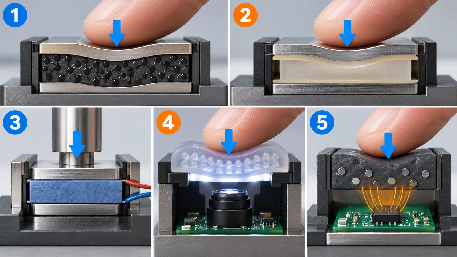
Tactile sensors can be sorted by what they use to read the fact that “contact deforms the rubber”. Here are five methods with the facts stated in primary sources.
Original SVG, detailed explanation and sources
Original SVG reference: Concept diagram (vector drawing). Concept diagrams of the five methods. The arrow shows the direction of pressing. Structures are simplified and not the exact internals of real sensors.
(1) Resistive: pressing changes resistance
Applying force to a conductive material changes its resistance. Tian et al. made a resistive pressure sensor with a foam-like structure of laser-scribed graphene and report a sensitivity of 0.96 kPa⁻¹ over a wide range of 0 to 50 kPaSourced[Ref. 10]. Pang et al., on the other hand, made random bumpy microstructures (spinosum-like) inspired by the epidermis, using abrasive paper as a template and reduced graphene oxide, and report a sensitivity of 25.1 kPa⁻¹ over 0 to 2.6 kPaSourced[Ref. 11]. The trade-off that a more sensitive sensor covers a narrower range shows in the numbers of the two papers (commentary).
(2) Capacitive: a narrower gap holds more charge
Rubber is sandwiched between two electrodes, and pressing narrows the gap and raises the capacitance. Mannsfeld et al. report that using thin PDMS (a silicone rubber) films with microstructures between the electrodes gave far higher pressure sensitivity than unstructured films of the same thickness, tunable by changing the microstructure, with very short response timesSourced[Ref. 9].
(3) Optical: photograph the deformation of a gel
GelSight covers a transparent rubber slab with a reflective membrane and photographs the pressed shape with an internal camera under lighting from several directions. Its strength is that the shape of the contact surface is known at high spatial resolution: 1 to 2 µm when optimized and 30 to 100 µm for the compact devices that fit a robot finger. Painting black dots between the rubber and the reflective membrane reveals shear and twisting force from the motion of the dotsSourced[Ref. 4]. DIGIT puts the same optical idea in a size that can be mounted on a multi-fingered robot hand (20 mm wide, 27 mm high, 18 mm deep, about 20 g) and gives a manufacturing cost estimate of about US$15 per unit in a batch of 1,000. The camera runs at 60 fps and the rubber gel can be replaced with a single screwSourced[Ref. 5].
(4) Magnetic: a moving magnetized rubber changes the field
Magnetic particles are mixed into rubber to make it magnetic, and magnetometers placed close by read the change in magnetic field as the rubber moves. uSkin is a soft skin with an array of elements measuring three-axis force (normal plus two lateral directions), with a center-to-center spacing of 4.7 mm in the flat version. Its new silicone structure reduced the crosstalk between force components, but the 3D-printed material had higher hysteresis than the previously used EcoflexSourced[Ref. 6]. ReSkin reads a 20 mm square area with five magnetometers and reports up to 400 Hz, 1 mm resolution (with 90% accuracy), a thickness of 2 to 3 mm, a cost under US$30 and accurate model predictions even beyond 50,000 interactionsSourced[Ref. 7].
(5) Fluid and impedance: the fluid path changes
BioTac has a rigid core surrounded by a rubber skin filled with a weakly conductive fluid. Electrodes on the core surface read the change in impedance (the resistance to alternating current) as force alters the fluid path. With a silicone skin whose inner surface is textured, forces from 0.1 to 30 N produced impedances from 5 to 1000 kΩ, with spatial resolution below 2 mm and frequency response above 50 Hz, both apparently limited only by the viscoelastic properties of the silicone skinSourced[Ref. 8].
Temperature is another important quantity for electronic skin. Someya et al. made networks of pressure and thermal sensors with organic-semiconductor transistors. Formed as a net they can be stretched by 25%, bent down to a 2 mm radius, and attached to the surface of an egg to obtain a pressure imageSourced[Ref. 14]. Ho et al. made a transparent, stretchable electronic skin from graphene alone, stacking humidity, thermal and pressure sensorsSourced[Ref. 12].
Sensitivity is how much the output changes for a small change in pressure (kPa⁻¹ in the examples above). Resolution can mean “the smallest difference in pressure” or “fineness of place (spatial resolution)”. The “resolution” in this article’s figure is the latter (commentary). Some sensors are very sensitive but coarse in place, and others are fine in place but narrow in force range, so decide which quantity the application needs.
5. Materials of electronic skin: rubber, graphene, particles and pigment
A review of electronic skin (Hammock et al., 2013) describes human skin as a stretchable network of sensors relaying tactile and thermal information to the brain, and organizes progress in electronic skin around making flexible, stretchable and robust devices over large areas, combined with several functions, for robots and prostheticsSourced[Ref. 3]. Here we look at the materials through concrete examples in primary sources.
- Conductive rubber: Sekitani et al. dispersed single-walled carbon nanotubes uniformly in a fluorinated copolymer with an ionic liquid, kept it soft up to 20 wt% nanotubes, and covered the composite film with siloxane rubber to get a conductivity of 57 S/cm and a stretchability of 134%. Combined with printed organic transistors it formed a 20 cm x 20 cm “rubberlike” active matrix that survived 70% stretching, and the paper points to mounting on moving parts such as the joints of a robot armSourced[Ref. 13].
- Graphene: Tian et al. reported a pressure sensor of laser-scribed foam-like grapheneSourced[Ref. 10]. Pang et al. made random epidermis-inspired microstructures by reducing graphene oxideSourced[Ref. 11]. Ho et al. made a transparent, stretchable, multifunctional electronic skin entirely of grapheneSourced[Ref. 12].
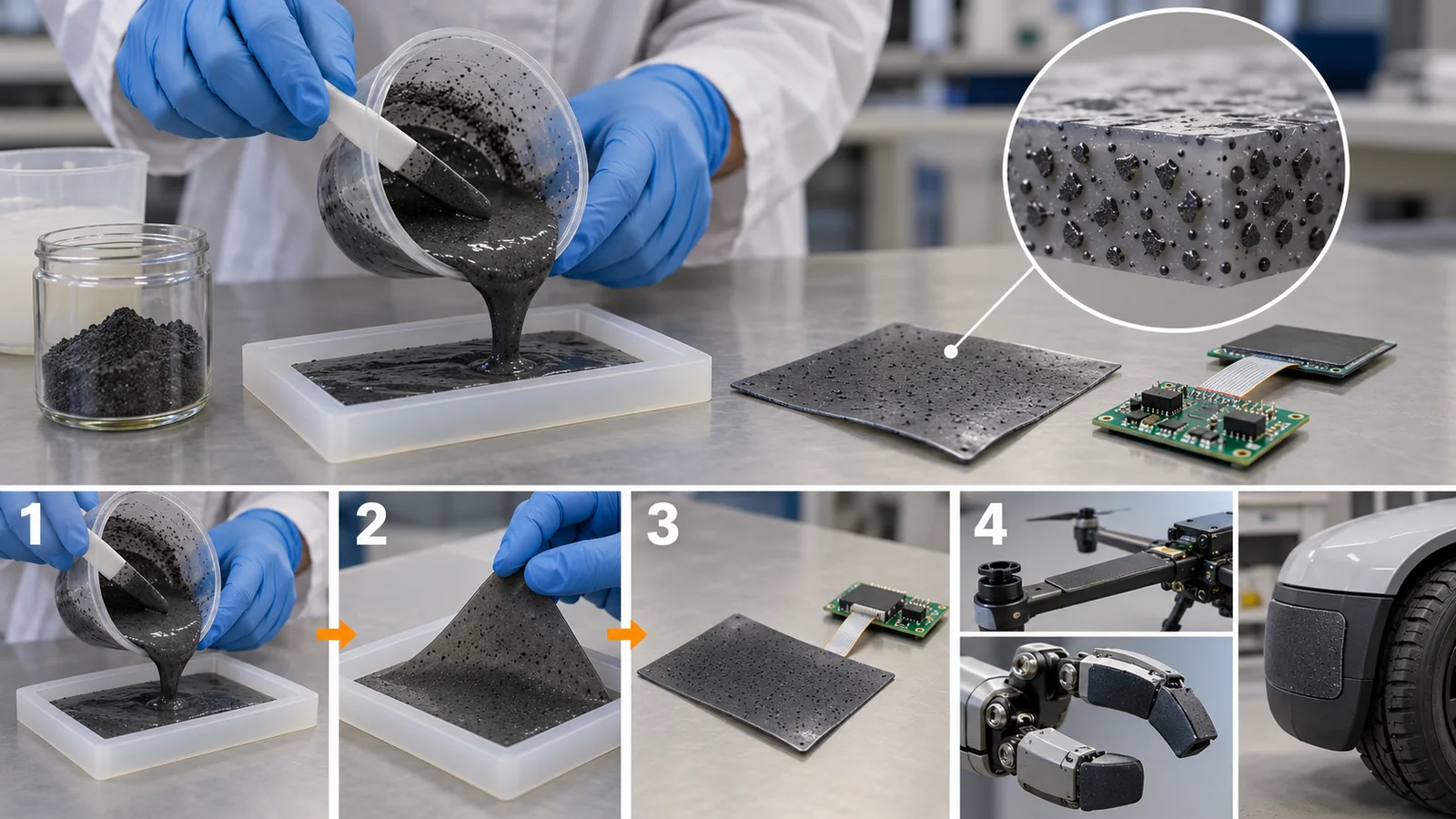
- Magnetic-particle rubber: ReSkin mixes magnetic microparticles (MQP-15-7) and a two-part silicone (Dragon Skin 10 NV) in a 2:1:1 ratio, pours it into a mold, and cures it at room temperature for at least three hours over a grid of small magnets for magnetization. The thickness is 2 to 3 mmSourced[Ref. 7].
- Pigment-sprayed gel: DIGIT airbrushes a silicone-based white pigment into a mold with a chemical kicker to form an “image transfer layer” of uniform thickness, then casts the base silicone over it and cures it. A thick layer deforms less and loses spatial resolution while a thin one is more easily damaged, so it iterated on the thickness to balance ruggedness and sensitivitySourced[Ref. 5].
In every method the tactile “skin” is soft rubber. The softer it is, the more it deforms under a small force and the more sensitive it is, but the more easily it wears. The DIGIT paper names as an issue that the “image transfer layer” at the contact surface wears from repeated touching and changes the sensor’s characteristics with useSourced[Ref. 5]. The ReSkin paper too says that the properties enabling soft contact lead directly to faster degradation, and made the skin replaceableSourced[Ref. 7]. Treating the skin as a consumable to be replaced is a way of absorbing the limits of material life through structure (commentary).
The magnetic particles of ReSkin are an extension of the same kind of materials science as motor magnets (see the article on permanent magnets and rare earths); the product name MQP-15-7 is understood to be a neodymium-based magnet powder (commentary). Unlike hard sintered magnets, dispersing the powder in rubber and magnetizing it over a grid of small magnets yields a soft, bendable magnetic skinSourced[Ref. 7]. The type, amount, dispersion and magnetization of the particles set the signal size and the variation between sensors (commentary). Because variation in response between sensors forces the model to be relearned at each replacement, uniformity of the material bears directly on practicalitySourced[Ref. 7].
6. Challenges: durability, wiring and variation
(1) Durability: abrasion destroys the skin
The DIGIT paper compared gel durability with an abrasion test. An industrial linear abrasion device (total weight 1.7 N, an H-18 abrasive tip) rubbed each surface in cycles of five sweeps, and light shone from below measured the increase in light passing through where the image transfer layer tore. After 5, 10 and 15 passes, the DIGIT gel showed 0, 0.3 and 0.3% degradation, a gel from another study 276, 482 and 805%, and a GelSight Inc. gel 475, 662 and 918%Sourced[Ref. 5]. The authors themselves note, however, that one of the gels compared was designed not for robots but for high-resolution 3D measurement and has a very thin opaque layer. This is the authors’ own test and does not rank products.
(2) Wiring: the more sensors, the more the wire count matters
Wiring each sensor separately needs as many wires as sensors. Wiring by rows and columns cuts the count to about 2 sqrt(n) but makes readout more complex (our calculation). Lee et al. say that earlier electronic skins send tactile information serially from the sensors, so readout latency and wiring complexity become bottlenecks as sensors multiply, and report that ACES (Asynchronously Coded Electronic Skin), which transmits simultaneously, read 240 artificial mechanoreceptors at a constant latency of 1 ms and keeps latency low for arrays beyond 10,000 sensorsSourced[Ref. 15]. The ReSkin paper also says resistive and capacitive soft sensors require many connections that lead to early failure and integration challengesSourced[Ref. 7]. uSkin used small control boards developed for the iCub skin, raising readout frequency and reducing the number of wiresSourced[Ref. 6].
(3) Variation and hysteresis: the same build does not give the same response
The uSkin paper says its 3D-printed silicone had higher hysteresis (an output that differs between loading and unloading) than the previously used EcoflexSourced[Ref. 6]. The ReSkin paper says that models learned from data often do not transfer to another sensor because of variation between sensors, and that relearning at every skin replacement is impracticalSourced[Ref. 7]. ReSkin therefore presents models that work out of the box on new skins and a self-supervised calibration to improve accuracy.
The facts: Electronic skin can outperform human skin in some quantities (pressure distribution and temperature). Hammock et al. state that e-skins already provide superior spatial resolution and thermal sensitivity to human skinSourced[Ref. 3]. But the whole picture of human skin, wide area, long life, robustness and reading much information over few wires, still has open issues (durability, wiring and variation above). “Can measure some quantity” is different from “equals human touch”.
7. Limits, what could not be confirmed, and a summary
- The numbers for each sensor are the authors’ reports in each paper and no third-party verification was confirmed. Definitions and conditions of sensitivity, resolution, price and life differ between sensors, so no ranking among methods is made.
- The price of BioTac and the life of commercial tactile sensors were not confirmed. The ReSkin paper’s statement that BioTac costs over US$1,000 is that team’s claim and is not adopted here.
- No international standard defining tactile-sensor performance was found. Only NIST’s draft (SP 1227) contains proposed ways to measure touch sensitivity and force calibration.
- The long-term reliability of materials such as graphene as sensors was not confirmed. What primary sources confirmed is initial performance such as sensitivity and range.
- Medical and health uses of electronic skin (skin-attached sensors) are not covered. This article is about robot touch.
- The density of touch units at the human fingertip is about 4.2 times that of the palm. Four groups of units sense changes and states separatelySourced[Ref. 1]
- Five methods: resistive, capacitive, optical, magnetic and fluid. Examples are graphene pressure sensors, microstructured PDMS, GelSight and DIGIT, uSkin and ReSkin, and BioTacSourced[Ref. 10, 9, 4, 5, 6, 7, 8]
- Pressure guide: light touch below 10 kPa, manipulation 10 to 100 kPa. Holding 0.5 kg on 1 cm² of fingertip gives about 49 kPaOur calculation[Ref. 10]
- The skin is a consumable. The abrasion test of the DIGIT gel and the replaceable structure of ReSkin respond to this problemSourced[Ref. 5, 7]
- More sensors make wiring the problem. For 16 x 16 = 256 sensors, one wire each is 256, rows and columns 32. ACES is reported to read 240 sensors at 1 ms latencyOur calculation[Ref. 15]
8. How to read the yardsticks and standards
The “quality” of a tactile sensor results from a combination of spatial resolution (fineness of place), sensitivity and measuring range, speed of response, ability to measure shear, hysteresis and variation, durability and price. What matters is that the same word can have different definitions and conditions. “Resolution” may be the spacing of sensor elements or the smallest distance that can actually be told apart. The table below organizes what could be confirmed (checked on 25 October 2026).
| What is evaluated | Typical tests and benchmarks (name, source) | Standards, rules and guidance (ISO, NIST and others) | Reading notes |
|---|---|---|---|
| Spatial resolution | GelSight 30 to 100 µm (for robot fingers), ReSkin 1 mm (90% accuracy), BioTac below 2 mm, uSkin 4.7 mm center to centerSourced[Ref. 4, 7, 8, 6] | Not found | “Resolution” and “element spacing” are different quantities. Check the conditions (object, force, calibration) |
| Sensitivity and measuring range | Tian et al. 0.96 kPa⁻¹ (0 to 50 kPa); Pang et al. 25.1 kPa⁻¹ (0 to 2.6 kPa); BioTac 5 to 1000 kΩ for 0.1 to 30 NSourced[Ref. 10, 11, 8] | Not found | High sensitivity tends to narrow the range. Check how sensitivity is defined (which output divided by what) |
| Speed of response | ReSkin up to 400 Hz; BioTac above 50 Hz; DIGIT camera 60 fps; ACES 1 ms latencySourced[Ref. 7, 8, 5, 15] | Not found | Sampling rate, sensor response and total delay differ. Detecting slip needs speed (commentary) |
| Durability | DIGIT: rubbed with an industrial linear abrasion device and degradation measured by the increase of transmitted light (0, 0.3, 0.3% after 5, 10, 15 passes); ReSkin: model accurate beyond 50,000 interactionsSourced[Ref. 5, 7] | Not found (the paper does not name a standard for the abrasion device) | The authors’ test. The gels compared were designed for different purposes. This is different from life in real use |
| Hysteresis and variation | uSkin: 3D-printed silicone has higher hysteresis than Ecoflex; ReSkin: variation between sensors makes learned models hard to transfer to another sensorSourced[Ref. 6, 7] | Not found | Variation in materials and manufacture becomes variation in performance (commentary) |
| How to measure touch in robot hands | NIST Draft SP 1227: proposed measurements such as Touch Sensitivity and Force CalibrationSourced[Ref. 16] | Not found (no test method that has become an international standard was confirmed)Not yet confirmed[Ref. 16] | A draft working document of October 2018; it may change in future |
| Price | DIGIT: manufacturing cost estimate of about US$15 per unit in a batch of 1,000; ReSkin: under US$30 (authors’ estimates)Sourced[Ref. 5, 7] | — (not a standard) | These are authors’ estimates, not market prices or production records |
The table layout is our organization (Our calculation). The content of the NIST draft was checked in the NIST document (checked 25 October 2026). No international standard numbers are treated in this article. ASTM standards are not covered.
Reading notes (for materials engineers)
- A demonstration, a benchmark and a real site are different. A laboratory sensor is measured with set objects, set forces and a new skin. In the field, abrasion, dirt, temperature and the effort of replacement come in.
- An author’s report and third-party verification are different. Sensitivity, resolution, price and life are each research team’s reports. Do not compare numbers whose conditions are not stated.
- A draft is not a standard. NIST SP 1227 is a working document toward standardization. Do not treat it like a finalized international standard.
- A plan and an achievement are different. “It will get cheaper at volume” and “the next generation will last longer” are plans, not achieved facts.
9. Glossary
- Touch (tactile sensing)
- The sense of force, shape, slip and temperature on contact.
- Electronic skin (e-skin)
- Electronic devices that, like human skin, cover wide areas, bend softly and sense touch and more.
- Receptive field
- The area of skin one touch unit senses.
- RA / SA
- Rapidly adapting / slowly adapting touch units.
- Pressure
- Force divided by area; unit pascal (Pa).
- Shear
- Force or deformation along the surface.
- Taxel
- One sensing point of a tactile sensor.
- Sensitivity
- How much the output changes for a small change in pressure.
- Spatial resolution
- Fineness of place: how close two points can be and still be told apart.
- Resistive sensor
- A sensor in which pressing changes the resistance of a conductive material.
- Capacitive sensor
- A sensor in which pressing changes electrode spacing and capacitance.
- Optical (vision-based) sensor
- A sensor in which a camera images the deformation of a rubber gel, such as GelSight and DIGIT.
- Magnetic sensor
- A sensor reading the motion of magnetic-particle rubber with magnetometers.
- Impedance
- The resistance to alternating current.
- PDMS
- Polydimethylsiloxane, a kind of silicone rubber.
- Elastomer
- A polymer material that stretches and recovers like rubber.
- Graphene
- A conductive material made of a single layer of carbon atoms.
- Carbon nanotube
- A tube-shaped carbon fiber used as a filler in conductive rubber.
- Hysteresis
- A mismatch of output between loading and unloading.
- Crosstalk
- Signals of another component mixing into the one to be measured.
- ACES
- Asynchronously Coded Electronic Skin: a scheme that transmits at once to reduce wiring and latency.
- Abrasion test
- A test rubbing a surface to see how easily it wears.
- Photometric stereo
- A method that finds surface shape from images under lighting from different directions.
- Bill of materials (BOM)
- A list of the parts, quantities and costs used in a product.
10. References (primary sources)
- Johansson R. S., Vallbo A. B. “Tactile sensibility in the human hand: relative and absolute densities of four types of mechanoreceptive units in glabrous skin”, The Journal of Physiology 286, 283–300 (1979), DOI 10.1113/jphysiol.1979.sp012619 — doi.org/10.1113/jphysiol.1979.sp012619
- Dahiya R. S., Metta G., Valle M., Sandini G. “Tactile Sensing—From Humans to Humanoids”, IEEE Transactions on Robotics 26(1), 1–20 (2010), DOI 10.1109/TRO.2009.2033627 — doi.org/10.1109/TRO.2009.2033627
- Hammock M. L. et al. “25th Anniversary Article: The Evolution of Electronic Skin (E-Skin): A Brief History, Design Considerations, and Recent Progress”, Advanced Materials 25, 5997–6038 (2013), DOI 10.1002/adma.201302240 — doi.org/10.1002/adma.201302240
- Yuan W., Dong S., Adelson E. H. “GelSight: High-Resolution Robot Tactile Sensors for Estimating Geometry and Force”, Sensors 17(12), 2762 (2017), DOI 10.3390/s17122762 — mdpi.com/1424-8220/17/12/2762
- Lambeta M. et al. “DIGIT: A Novel Design for a Low-Cost Compact High-Resolution Tactile Sensor with Application to In-Hand Manipulation”, IEEE Robotics and Automation Letters (2020), arXiv:2005.14679 — arxiv.org/abs/2005.14679
- Tomo T. P. et al. “A New Silicone Structure for uSkin—A Soft, Distributed, Digital 3-Axis Skin Sensor and Its Integration on the Humanoid Robot iCub”, IEEE Robotics and Automation Letters 3(3), 2584–2591 (2018), DOI 10.1109/LRA.2018.2812915 — doi.org/10.1109/LRA.2018.2812915
- Bhirangi R. et al. “ReSkin: versatile, replaceable, lasting tactile skins”, Proceedings of Machine Learning Research 164, 587–597 (2022), arXiv:2111.00071 — arxiv.org/abs/2111.00071
- Wettels N., Santos V. J., Johansson R. S., Loeb G. E. “Biomimetic Tactile Sensor Array”, Advanced Robotics 22, 829–849 (2008), DOI 10.1163/156855308X314533 — doi.org/10.1163/156855308X314533
- Mannsfeld S. C. B. et al. “Highly sensitive flexible pressure sensors with microstructured rubber dielectric layers”, Nature Materials 9, 859–864 (2010), DOI 10.1038/nmat2834 — nature.com/articles/nmat2834
- Tian H. et al. “A Graphene-Based Resistive Pressure Sensor with Record-High Sensitivity in a Wide Pressure Range”, Scientific Reports 5, 8603 (2015), DOI 10.1038/srep08603 — doi.org/10.1038/srep08603
- Pang Y. et al. “Epidermis Microstructure Inspired Graphene Pressure Sensor with Random Distributed Spinosum for High Sensitivity and Large Linearity”, ACS Nano 12, 2346–2354 (2018), DOI 10.1021/acsnano.7b07613 — doi.org/10.1021/acsnano.7b07613
- Ho D. H. et al. “Stretchable and Multimodal All Graphene Electronic Skin”, Advanced Materials 28, 2601–2608 (2016), DOI 10.1002/adma.201505739 — doi.org/10.1002/adma.201505739
- Sekitani T. et al. “A Rubberlike Stretchable Active Matrix Using Elastic Conductors”, Science 321, 1468–1472 (2008), DOI 10.1126/science.1160309 — doi.org/10.1126/science.1160309
- Someya T. et al. “Conformable, flexible, large-area networks of pressure and thermal sensors with organic transistor active matrixes”, Proceedings of the National Academy of Sciences 102, 12321–12325 (2005), DOI 10.1073/pnas.0502392102 — doi.org/10.1073/pnas.0502392102
- Lee W. W. et al. “A neuro-inspired artificial peripheral nervous system for scalable electronic skins”, Science Robotics 4, eaax2198 (2019), DOI 10.1126/scirobotics.aax2198 — doi.org/10.1126/scirobotics.aax2198
- Falco J., Van Wyk K., Messina E. “Performance Metrics and Test Methods for Robotic Hands”, NIST Draft Special Publication 1227 (October 2018; a working document of the IEEE RHGM technical committee, a draft) — nvlpubs.nist.gov/nistpubs/SpecialPublications/NIST.SP.1227-draft.pdf
11. Claim-to-source audit
| Claim in the text | Basis | Type |
|---|---|---|
| Four groups of touch units (RA, PC, SA I, SA II), 334 recorded units, relative density 1 : 1.6 : 4.2, the difference mainly from RA and SA I | Johansson and Vallbo (1979) Reference 1 https://doi.org/10.1113/jphysiol.1979.sp012619 | Sourced |
| The review of robot touch: starting from human touch, design hints, technologies, extension to the whole body, remaining issues | Dahiya et al. (2010) Reference 2 https://doi.org/10.1109/TRO.2009.2033627 | Sourced |
| The e-skin review: how human skin is viewed, and e-skins already superior in spatial resolution and thermal sensitivity | Hammock et al. (2013) Reference 3 https://doi.org/10.1002/adma.201302240 | Sourced |
| GelSight: transparent rubber plus reflective membrane, camera and lighting, resolution 1 to 2 µm (optimized) and 30 to 100 µm (robot fingers), black dots for lateral displacement, force and twist, Pressure Profile Systems array 5 mm, contact force and slip inferred from deformation | Yuan et al. (2017) Reference 4 https://www.mdpi.com/1424-8220/17/12/2762 | Sourced |
| DIGIT: 20 x 27 x 18 mm and about 20 g, 60 fps, about US$15 per unit (1,000 units), gel construction, layer-thickness trade-off, abrasion test (0, 0.3, 0.3% versus 276, 482, 805% and 475, 662, 918% after 5, 10, 15 passes), single-screw replacement | Lambeta et al. (2020) Reference 5 https://arxiv.org/abs/2005.14679 | Sourced |
| uSkin: three axes, 4.7 mm center-to-center (flat version), reduced crosstalk, hysteresis of 3D-printed silicone, wire reduction with iCub boards | Tomo et al. (2018) Reference 6 https://doi.org/10.1109/LRA.2018.2812915 | Sourced |
| ReSkin: MQP-15-7 magnetic microparticles and Dragon Skin 10 NV at 2:1:1, five magnetometers over 20 mm square, 400 Hz, 1 mm (90%), 2 to 3 mm thick, under US$30, over 50,000 interactions, replacement, the list of desirable properties, and the authors’ remarks on other methods | Bhirangi et al. (2022) Reference 7 https://arxiv.org/abs/2111.00071 | Sourced |
| BioTac: rigid core, weakly conductive fluid, rubber skin, electrode impedance, 5 to 1000 kΩ for 0.1 to 30 N, resolution below 2 mm, above 50 Hz | Wettels et al. (2008) Reference 8 https://doi.org/10.1163/156855308X314533 | Sourced |
| Capacitive pressure sensors using microstructured PDMS being more sensitive than unstructured films, tunable, with short response | Mannsfeld et al. (2010) Reference 9 https://www.nature.com/articles/nmat2834 | Sourced |
| Laser-scribed graphene resistive sensor 0.96 kPa⁻¹ (0 to 50 kPa), light touch below 10 kPa and manipulation 10 to 100 kPa | Tian et al. (2015) Reference 10 https://doi.org/10.1038/srep08603 | Sourced |
| Reduced-graphene-oxide sensor with random microstructure at 25.1 kPa⁻¹ (0 to 2.6 kPa) and the sensitivity-linearity trade-off | Pang et al. (2018) Reference 11 https://doi.org/10.1021/acsnano.7b07613 | Sourced |
| A transparent, stretchable, multifunctional all-graphene e-skin (humidity, temperature, pressure) | Ho et al. (2016) Reference 12 https://doi.org/10.1002/adma.201505739 | Sourced |
| Carbon nanotube composite: 57 S/cm, 134% stretchability, 20 wt%, 20 cm x 20 cm active matrix, 70% stretching, mention of robot joints | Sekitani et al. (2008) Reference 13 https://doi.org/10.1126/science.1160309 | Sourced |
| Pressure and thermal sensor network with organic transistors: 2 mm bend radius, 25% extension, pressure image on an egg | Someya et al. (2005) Reference 14 https://doi.org/10.1073/pnas.0502392102 | Sourced |
| ACES: 1 ms latency with 240 sensors, low latency beyond 10,000, and earlier e-skins sending serially having latency and wiring bottlenecks | Lee et al. (2019) Reference 15 https://doi.org/10.1126/scirobotics.aax2198 | Sourced |
| The measurement items of NIST Draft SP 1227 (October 2018) (touch sensitivity, force calibration and others) and its status as a working-document draft | NIST draft Reference 16 https://nvlpubs.nist.gov/nistpubs/SpecialPublications/NIST.SP.1227-draft.pdf | SourcedNot yet confirmed |
| 4.9 N / 1 cm² = about 49 kPa, 1 kPa = 1,000 Pa, 256 sensors needing 256 and 32 wires, 2 sqrt(n), and 256 x 100 Hz x 12 bits = about 307 kbit/s | Our calculation (4.9 N from the previous article and an assumed 1 cm²; illustrative) | Our calculation |
| The plain explanation of rapidly and slowly adapting, the difference between sensitivity and resolution, the materials engineer’s views, the decision not to rank methods, and MQP-15-7 being understood as a neodymium-based powder | Our own commentary based on general textbook understanding | Commentary |
| An international standard for tactile sensors, the price of BioTac and the life of commercial products, the long-term reliability of graphene sensors, and the standard name of the abrasion device | Not stated because they could not be confirmed within this survey | Commentary |
Last updated: 25 October 2026. Sources are limited to primary material (peer-reviewed papers, arXiv papers and a NIST draft). Estimates from research firms and figures reported only in the news are not used. Numbers marked as our calculation rest on illustrative assumptions. An international standard for tactile sensors, the price of BioTac and the life of commercial products, and the long-term reliability of graphene sensors could not be confirmed and are not stated. Figures 1 and 7 are ImageGen-generated conceptual illustrations; the rest are explanatory concept diagrams or drawings that include our calculation.