TECHNOLOGY EXPLAINER
Joint Actuators
— The robot’s “muscle unit” that combines motor, reducer, sensors and control
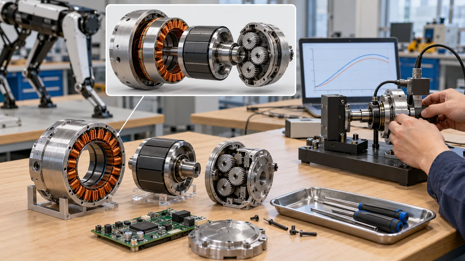
The joints of humanoid and legged robots are small machines that combine motor, reducer, encoder, driver and bearing in one. This article explains in plain terms, with numerical examples, frameless motors and torque density, the difference between sustained and peak torque and heat, quasi-direct-drive and linear actuators, and how to read parts cost.
For materials engineers, it shows how copper, magnets, electrical steel, insulating resin, steel, aluminum, grease and cables work together in one joint.
- Short version / before you read / place in the series
- Inside a joint
- The motor: frameless and gap radius
- Heat: continuous and peak
- Design philosophies
- Linear joints: planetary roller screw
- How to read parts cost
- A joint through a materials engineer’s eyes
- Limits and summary
- How to read the yardsticks and standards
- Glossary
- References
- Claim-to-source audit
Sourced = stated in a published source (link given)
Our calculation = a value this article calculated from stated assumptions
Not yet confirmed = drafts, plans, targets and other items that are not settled
Our own readings for materials and design are marked as commentary. Inference is shown in bold. Every analogy comes with its limits.
Actuator masses, torques and parts costs are table values from the papers of Berkeley Humanoid and Berkeley Humanoid Lite (home-built research robots), in small quantities and at US prices. The performance or cost of commercial humanoids and company selling prices or volume targets are not used. “Our calculation” is computed from table values in the papers and stated assumptions. Frameless-motor values are maker-stated. For standards only number, title, edition and date were checked, not the paid text. ASTM standards are not covered. Checked 25 October 2026.
1. The short version / what to know first / where this fits in the series
- A joint actuator is a “muscle unit for a joint” that combines motor, reducer, sensors, driver and bearings in one. The home-built actuators of Berkeley Humanoid contain a reducer (a 9:1 planetary gear), have a hollow shaft for cables, and mount directly through a cross roller bearingSourced[Ref. 1].
- Read “torque density” separately for peak and sustained. The 8513 actuator (756 g) in the same study has a peak torque of 45.3 N·m and a sustained torque of 18.9 N·m, or about 60 and 25 N·m/kgSourcedOur calculation. Heat rises with the square of torque, so at peak the heat is about 5.7 times that at sustained torque and can be tolerated only brieflyOur calculation.
- How to read parts cost: In two research humanoids the actuators made up about 69% and about 81% of the parts cost (small-quantity US-price bills of materials)Our calculation[Ref. 1, 2]. This is not the cost of commercial humanoids.
No prior knowledge is needed. A motor is a machine that turns electricity into rotation with magnets and coils. In robots it is combined with a reducer (see the article on speed reducers and gears) to make an actuator, the robot’s muscle. A joint is a small machine that adds an angle sensor and a driver controlling the current. Torque is the turning force (N·m) and torque density is torque per unit of weight (N·m/kg). The whole picture of robots is in the article “Introduction to Drones and Robotics”.
If the previous article on speed reducers and gears is about gears, this one is about the whole joint. Magnets are covered in the article on permanent magnets and rare earths, artificial muscles in the article on soft actuators, batteries in the one on power sources, and control in the one on the fundamentals of robot control.
2. Inside a joint: what is in it
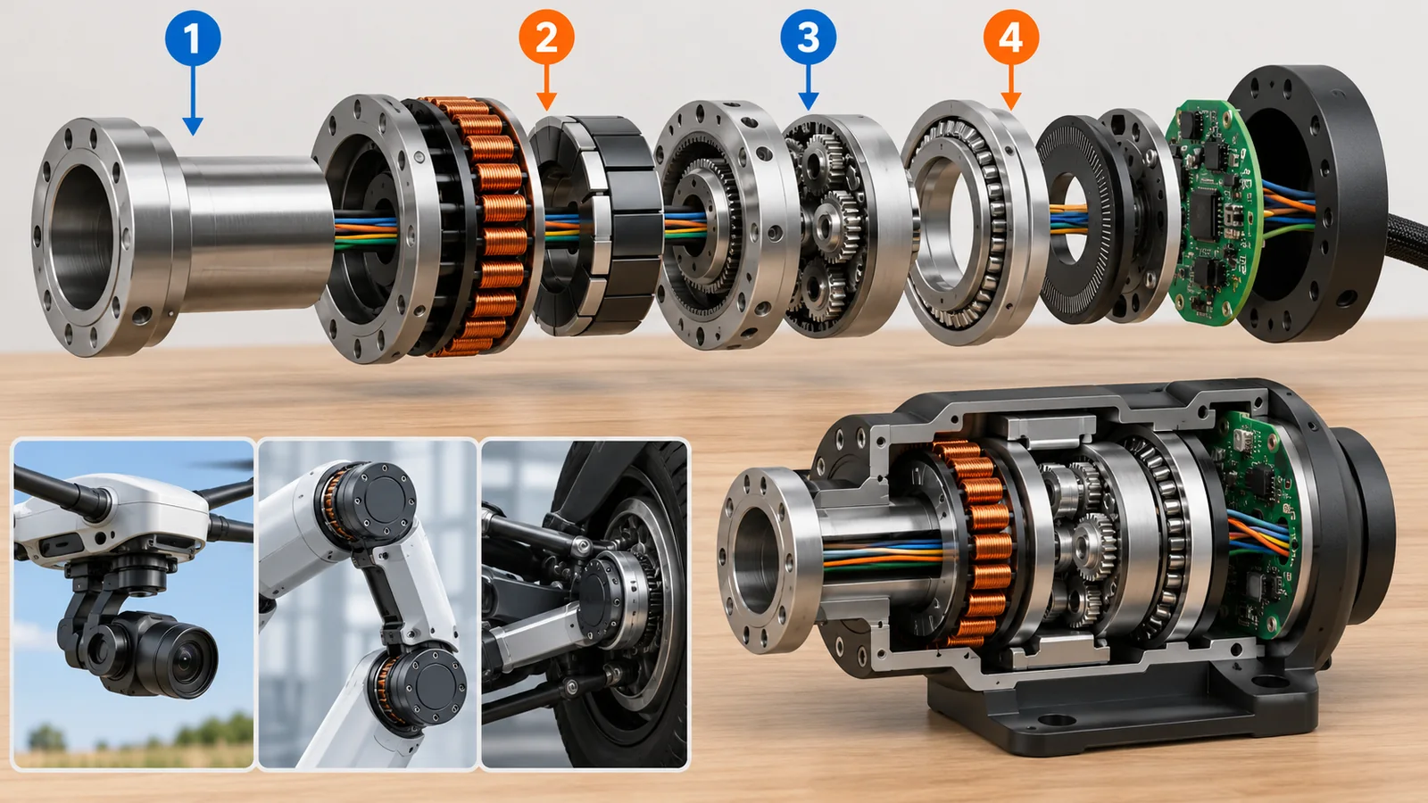
Open a robot joint and you find these parts packed in: (1) the motor (copper windings on the stator and magnets on the rotor); (2) the reducer; (3) the encoder (a sensor that measures angle); (4) the driver (a circuit that turns battery power into the current the motor needs); (5) the bearing (which takes the load on the output side); and (6) the case, wiring and temperature sensors.
Original SVG, detailed explanation and sources
Original SVG reference: Concept diagram (vector drawing). Concept diagram of a joint actuator. The order and size of parts are illustrative and are not the structure of a specific product. The red dashed line shows the hollow-shaft idea of passing wiring through the axis.
The Berkeley Humanoid paper says almost every part was custom-built, the reducer was integrated into the actuator, and a hollow shaft was used in most of them. The reason is that friction and vibration from contact with the environment are a major challenge for the durability of power and signal cables; running the cables through the hollow shaft reduced rubbing as the joint movesSourced[Ref. 1]. A cross roller bearing on the output side lets the actuator be mounted directly as the joint. The reducer is a 9:1 planetary gear (quasi-direct drive, QDD), and because joint torque can be estimated from motor current, no strain gauges were addedSourced[Ref. 1].
A motor’s torque is roughly proportional to the current flowing through it (commentary). So measuring the current gives a hint of the torque. This estimate works for a joint with a low ratio and little friction (easy to backdrive). In a joint with a high ratio and more friction, the gap to the output torque is larger, so a separate torque sensor may be added (commentary). The point is that the number of sensors in a joint depends on the design philosophy.
3. The motor: frameless and the “gap radius”
Joints often use frameless motors. A frameless motor has no outer case, shaft or bearings: only the stator and rotor are sold as parts, and the designer builds them directly into the joint housing. The Allied Motion HT series page describes its frameless torque motors as suited to direct integration on an axis where a rotor-stator component solution is better than a housed motor, and states a hollow bore of up to 63.5 mm and nine frame sizes with continuous stall torque from 0.008 to 9.2 N·mSourced[Ref. 4].
So which shape of motor favors torque density? The MIT Cheetah paper (Wensing et al.) focused on the gap radius, the radius of the magnetic interface between rotor and stator. In simple theory, torque is 2π x radius squared x length x shear stress, and mass is proportional to radius and length, so length does not change the density while a larger radius raises it. In catalog values for the Emoteq HT series (frameless), the paper reports torque density roughly proportional to the 0.8th power of radius and torque per rotor inertia proportional to the radius to the power -1.6Sourced[Ref. 3].
Checking with numbers (Our calculation): doubling the gap radius gives, by the catalog trend, a torque density of 2^0.8 = about 1.7 times and a torque per rotor inertia of 2^-1.6 = about 0.33 times. A larger radius gives more torque for the same weight but a heavier rotor and less agility (ease of acceleration). The paper adds that winding and manufacturing considerations mean this trend alone should not decide a design[Ref. 3].
In the paper’s relation, shear stress is proportional to current x magnetic flux density of the magnets x number of conductors / cross-sectional area[Ref. 3]. To raise torque density, therefore, you need (1) strong magnets (flux density) and (2) copper windings, insulation and heat-removal structures that can carry as much current as can be cooled (commentary). The loss of magnet performance with temperature (coercivity) is covered in the series article on permanent magnets and rare earths.
4. Heat: what it can give continuously and what it can give briefly
When current flows, the motor winding’s resistance produces heat (Joule heat, current squared times resistance). Torque is roughly proportional to current, so heat grows with the square of torque (commentary). A motor’s specification therefore lists separately the sustained (continuous) torque, which it can give continuously within the thermal limit, and the peak torque, which it can give only briefly.
Checking with numbers (Our calculation): the 8513 has a peak of 45.3 N·m against a sustained 18.9 N·m. The torque ratio is 45.3 / 18.9 = 2.4, so heat is 2.4 squared = about 5.7 times. At half the sustained torque (9.45 N·m), heat is a quarter. The MIT Cheetah paper notes that in leg motion the share of time at high torque is small, so the continuous-torque limit is not always the constraint and density can be gained from brief peaksSourced[Ref. 3].
The facts: Peak torque exceeds the thermal limit, so it can be given only briefly. What can be used continuously is up to the sustained (continuous) torque. Running long at peak heats the windings and magnets and leads to insulation degradation and magnet demagnetization (commentary). When a humanoid specification just says “torque”, check whether it is peak or sustained, for how many seconds, and under what cooling conditions.
Heat produced in the windings escapes through the insulation coating and impregnating resin, the iron core, the housing and then the structure. The heat-resistance temperature of the insulation, the thermal conductivity of the resin, the conduction of the aluminum housing and the contact at the interfaces together decide the sustained torque (commentary). IEC 60034-1 is the standard for ratings and performance of rotating electrical machines, and its 15th edition appeared in March 2026. The list of changes in this edition includes updated values for a thermal class (the heat-resistance class of insulation)Sourced[Ref. 7].
5. Joint design philosophies: a high ratio or quasi-direct drive
The Berkeley Humanoid paper groups humanoid joints roughly as follows. Large (adult-size) research robots often use high-ratio strain wave actuators and can walk and do simple arm motions. Lightweight (child-size and similar) robots use quasi-direct-drive (QDD) actuators and can do more dynamic motions. The paper also says, citing other literature, that Tesla Optimus uses linear actuators and strain wave gears, some with load cells (force sensors)Sourced[Ref. 1] (this is the paper’s statement, not the company’s own material).
| Philosophy | Ratio | Strengths | Weaknesses (commentary) | Example in a primary source |
|---|---|---|---|---|
| High ratio | Large (strain wave, RV) | Holding position; large force from a small motor | High reflected inertia; will not yield when pushed; weak against impact | Said to be common in adult-size research robots[Ref. 1] |
| Quasi-direct drive (QDD) | Small (planetary gear of several to a dozen to 1) | Yields to impact (backdrivable); torque can be estimated from current | Needs a larger motor for the same torque, with more heat | MIT Cheetah leg 1:5.8[Ref. 3]; Berkeley Humanoid 9:1[Ref. 1] |
| Linear (roller screw and similar) | Set by the screw lead | Joints such as knee or ankle that need large linear force | Screw accuracy, lubrication, weight and cost are issues (commentary) | Review of planetary roller screws[Ref. 5] |
The grouping combines the paper’s summary and our commentary. It is not a table ranking products or companies.
What happens when the size changes within one design
Berkeley Humanoid built four actuators, all 9:1 but with different motor sizes (5013, 8513, 8518, 10413). Computing torque per weight from the table’s masses and torques gives about 39 to 80 N·m/kg at peak and about 18 to 34 N·m/kg sustained, rising with sizeSourcedOur calculation[Ref. 1]. This agrees with the trend of the previous chapter that a larger motor radius raises torque density (commentary).
6. Linear joints: the planetary roller screw
In joints such as the knee or ankle, where large force is wanted in a straight line, actuators giving linear force instead of rotation are sometimes used. The planetary roller screw is one. Several threaded rollers sit between a screw shaft and a nut, converting rotation into linear motion (or the reverse). A review paper explains that by using rollers to carry load and transmit motion, the mechanism has more load-bearing contact points than a ball screw and can more easily give a larger radius of curvature at the contactSourced[Ref. 5].
Checking with numbers (Our calculation): with a screw lead of 2 mm and a motor at 3000 rpm (50 turns per second), the linear speed is 2 mm x 50 = 100 mm/s. To push 1000 N, the required torque, assuming 0.8 efficiency, is T = F x L / (2π x efficiency) = 1000 x 0.002 / (2π x 0.8) = about 0.40 N·m. That is, this screw makes about 2,500 N of force from 1 N·m of rotation. It helps to think of the screw lead as playing the role of the “reduction ratio” of a reducer (commentary).
A ball screw has steel balls rolling between threads. A planetary roller screw uses threaded cylindrical rollers instead. A roller can take load over a contact closer to a line than a ball can, so it is said to carry larger loads in the same size (commentary, based on the review’s statement about more contacts)[Ref. 5]. However, thread accuracy and lubrication govern performance, and fatigue, slip and wear are treated as research topics.
7. How to read parts cost: within what the sources show
Talk about the “price” of humanoid robots is full of news and estimates, but here we use only two research papers that publish their bills of materials (BOM). For Berkeley Humanoid (without arms, small quantity) the parts cost is about US$9,955, of which 12 actuators are US$6,894, about 69%. For Berkeley Humanoid Lite (many 3D-printed parts) the parts cost is US$4,312 (US prices), and 22 actuators are US$3,512, about 81%Our calculation[Ref. 1, 2].
- Actuators dominate parts cost. In the two research robots, 70 to 80 percent was in the jointsOur calculation. The parts that set performance and the parts that set cost are the same (commentary).
- Larger actuators cost less per newton-metre of peak torque. In the Berkeley Humanoid table the figures are US$43.5 (5013), US$12.6 (8513), US$10.2 (8518) and US$8.3 (10413) per peak N·mOur calculation[Ref. 1].
- That costs fall with volume is the paper’s own statement. The paper says most costs in the table will decrease with scaled-up production but does not say by how much. This article treats this as not yet confirmedNot yet confirmed[Ref. 1].
The facts: The numbers above are the parts cost of small robots built by university research teams. Commercial humanoids differ in size, performance, safety requirements, production volume, labor cost and profit. Selling prices announced by companies and targets such as “aiming for US$X at volume production” are company claims or targets (not yet confirmed) and are not used in this article.
8. A joint through a materials engineer’s eyes: the combination of materials
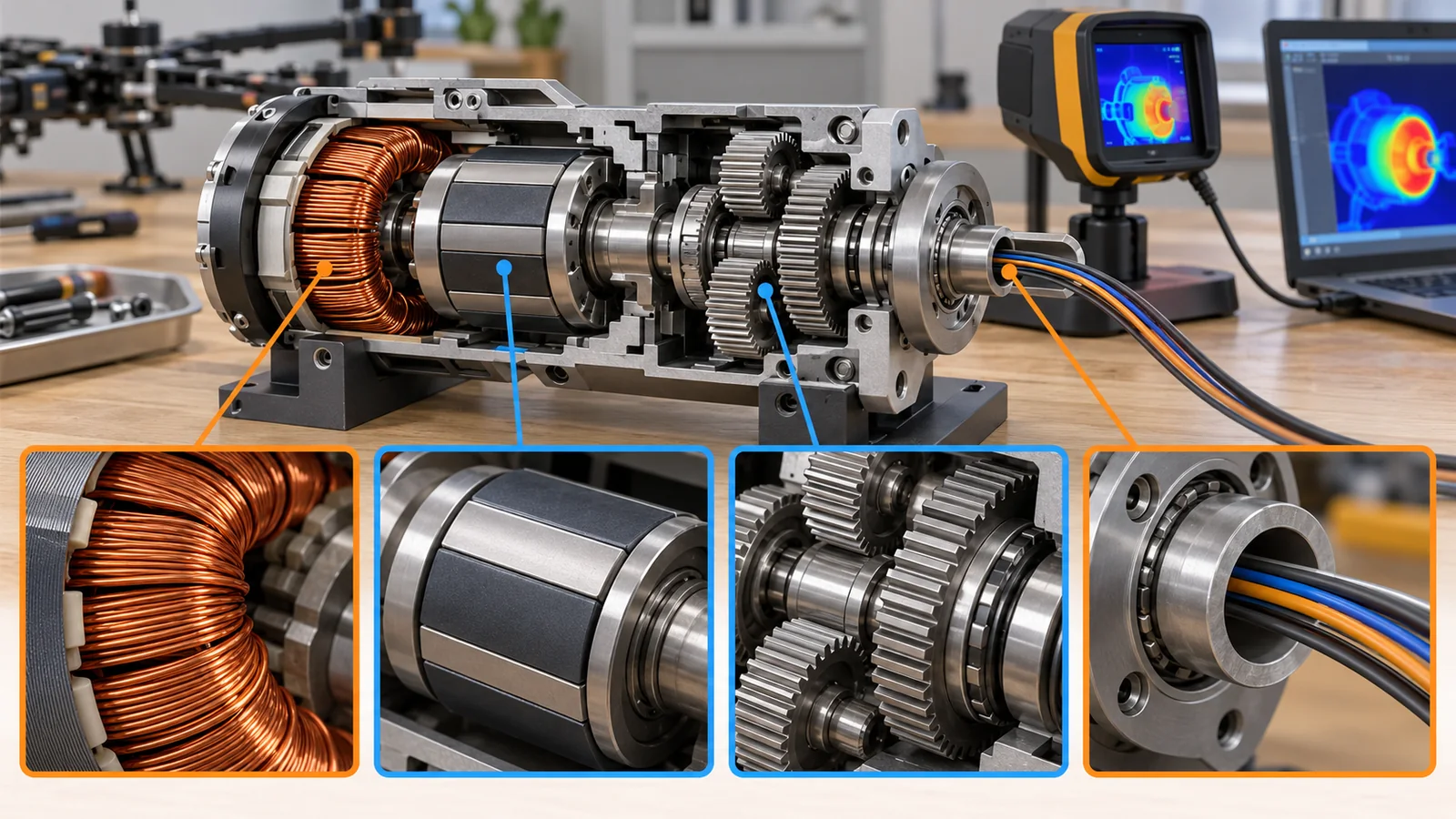
Inside a joint, copper (windings), magnets (rotor), electrical steel (iron core), insulating resin (coating and impregnation), steel (gears), aluminum alloy (housing), grease and cable sheaths all work at once (commentary). The Berkeley Humanoid paper says it used 7075 and 6061 aluminum alloys for the main parts and SKD11 steel for the gearbox and linkage, making a light structure that survives impactSourced[Ref. 1]. Berkeley Humanoid Lite, in contrast, uses 3D-printed PLA parts for structure and gears and reinforces them with through-screws and embedded brass hex stands to prevent failure along layer boundariesSourced[Ref. 2]. Even for the same “joint”, the choice of materials changes the balance among strength, weight, cost and ease of fabrication.
Cables are also a materials issue. The Berkeley Humanoid paper says that cables tearing under friction and vibration from contact with the environment is a major reliability challenge, which is why it used hollow shaftsSourced[Ref. 1]. The flex life of cable sheaths and conductors is as important as the motor or gears in a robot whose joints move millions of times (commentary).
9. Limits, what could not be confirmed, and a summary
- Most numbers come from the papers of one research robot. They are table values for the home-built actuators of Berkeley Humanoid and Berkeley Humanoid Lite, not commercial products or other makers’ values. No ranking is made among products of different sizes and conditions.
- The joint structure and parts cost of commercial humanoids could not be confirmed. Numbers that rest only on company material or announcements are not used in this article.
- The frameless-motor values are stated values on one maker’s page. The Allied Motion HT series gives only a torque range, and mass and price were not confirmed.
- No international standard for the whole joint actuator was found. For the motor alone (IEC 60034-1), robot safety (ISO 10218-1) and safety-related parts of control (ISO 13849-1), only number, title and edition were checked, not the text.
- The planetary roller screw is treated within what a review paper says. Specific adoption in humanoid robots and its performance were not confirmed in primary sources.
- A joint actuator is an integrated unit of motor, reducer, sensors, driver and bearing. A hollow shaft and a cross roller bearing simplify wiring and mountingSourced
- Read torque density separately for peak and sustained. Heat goes as torque squared; the 45.3 N·m peak makes about 5.7 times the heat of the 18.9 N·m sustained torqueOur calculation
- A larger gap radius tends to raise torque density. Doubling the radius gives about 1.7 times, but torque per inertia falls to about 0.33 timesOur calculation
- Low-ratio quasi-direct drive tolerates impact at the price of a larger motor and more heat. In linear joints the screw lead plays the role of the reduction ratioSourced
- In two research humanoids, about 69% and about 81% of the parts cost was in the actuators. These are small-quantity US-price bills of materials, not the cost of commercial machinesOur calculation
10. How to read the yardsticks and standards
The “quality” of a joint actuator results from a combination of torque density (torque per weight), sustained and peak torque, efficiency, backdrivability, bandwidth (agility), durability and cost. What matters is what a number includes and under what conditions it was measured. “Torque density”, for example, can differ several times depending on whether the driver and bearings are in the mass and whether peak or sustained torque is used. The table below organizes what could be confirmed (checked on 25 October 2026).
| What is evaluated | Typical tests and benchmarks (name, source) | Standards, rules and guidance (ISO, IEC, JIS and others) | Reading notes |
|---|---|---|---|
| Torque density | Torque per weight (N·m/kg), computed from the peak and sustained torques and masses in the Berkeley Humanoid table[Ref. 1]Our calculation | Not found (no international standard defining the mass boundary or the peak/sustained distinction was confirmed) | Always check what the mass includes (driver, bearing, housing) and whether the figure is peak or sustained |
| Sustained (continuous) torque and temperature | Torque that can be given continuously within the thermal limit (definition in Wensing et al.); winding heat goes as current squared[Ref. 3]Sourced | IEC 60034-1:2026 (rating and performance of rotating machines; Edition 15, 13 March 2026)[Ref. 7]Sourced. Whether it applies directly to robot joint modules was not confirmed | Sustained torque changes with cooling conditions (ambient temperature, mounting). The standard text is paid and was not checked |
| Efficiency | Dynamometer measurement distinguishing mechanical efficiency (gears only) from total efficiency (including motor and driver) (Berkeley Humanoid Lite); conditions on which reducer efficiency depends (HD catalog)[Ref. 2][Ref. 6]Sourced | Not found | Check which efficiency (mechanical or total) and at which torque and speed. Efficiency falls at low load |
| Backdrivability | Impact mitigation factor (IMF): a metric for backdrivability at impact (Wensing et al., 2017)[Ref. 3]Sourced | Not found | A metric from a research paper, not a standard. Check the definition before comparing with values in other papers |
| Durability | 60-hour durability test (lifting a 0.5 kg, 0.5 m pendulum at 0.5 Hz with periodic measurement of efficiency and backlash) and agreement of efficiency across six actuators (Berkeley Humanoid Lite)[Ref. 2]Sourced | Not found | One team’s test; 60 hours is orders of magnitude below working life. The result “within acceptable limits” is the authors’ judgement |
| Pose performance of the robot | Test methods for pose accuracy and repeatability (ISO 9283) | ISO 9283:1998 (confirmed in 2021, now under review)[Ref. 10]Sourced | This is for the whole robot, not for a joint |
| Safety function of a joint | — (conformity standards, not a performance number) | ISO 10218-1:2025 (safety of industrial robots, February 2025) and ISO 13849-1:2023 (safety-related parts of control systems, April 2023)[Ref. 9, 8]Sourced | The requirements themselves were not checked. A standard usually binds only when cited by law or contract (commentary) |
| Cost | Published bills of materials: Table 3 of Berkeley Humanoid and Table III of Berkeley Humanoid Lite[Ref. 1, 2]SourcedOur calculation | — (not a standard) | Small-quantity research-grade US prices; not the cost of commercial machines. Cost reduction at volume is the paper’s statement (not yet confirmed) |
The table layout is our organization (Our calculation). Numbers, titles, editions and dates were checked on the official ISO and IEC pages (checked 25 October 2026). Standard texts are paid, so only titles and scope are given. ASTM standards are not covered.
Reading notes (for materials engineers)
- A demonstration, a benchmark and a real site are different. A dynamometer test in a lab controls temperature, load and speed. A real robot adds ambient temperature, impacts and dirt.
- A maker’s stated value and third-party verification are different. Catalog values for frameless motors and reducers are under the maker’s conditions, and values in research papers come from that team’s own tests.
- Standards may be recommendations or requirements. IEC and ISO standards generally bind only when cited by law or contract (commentary).
- A plan and an achievement are different. “Costs will fall at volume” and “the next generation will perform better” are plans, not achieved facts.
11. Glossary
- Joint actuator
- A unit that moves a joint, combining motor, reducer, sensors, driver and bearing.
- Stator
- The fixed side of a motor, carrying the copper windings.
- Rotor
- The rotating side of a motor, carrying the magnets.
- Frameless motor
- A motor supplied as stator and rotor parts only, without case, shaft or bearings.
- Gap radius
- The radius of the magnetic interface between rotor and stator.
- Torque
- The turning force; unit N·m.
- Torque density
- Torque per unit of weight (N·m/kg).
- Sustained (continuous) torque
- Torque that can be given continuously within the thermal limit.
- Peak torque
- The maximum torque that can be given briefly.
- Joule heat
- Heat produced when current flows through a resistance (current squared times resistance).
- Encoder
- A sensor measuring rotation angle.
- Driver (inverter)
- A circuit that turns battery power into the current the motor needs.
- Hollow shaft
- A shaft with a central bore through which wiring can pass.
- Cross roller bearing
- A bearing with rollers arranged crosswise that takes loads in any direction in one unit.
- Quasi-direct drive (QDD)
- A scheme with a small reduction ratio that keeps motor-like behavior (easy to backdrive).
- Backdrivability
- The ability to be moved from the output side, motor included.
- Reflected inertia
- The effect that the motor rotor looks, from the output, like an inertia multiplied by the square of the ratio.
- Impact mitigation factor (IMF)
- A metric for how well backdrivability mitigates impact.
- Planetary roller screw
- A mechanism with threaded rollers between a screw shaft and a nut that converts rotation into linear motion.
- Lead
- The distance a screw advances in one turn.
- Electrical steel
- Thin steel sheet with low magnetic loss, used for motor iron cores.
- Thermal class
- The classification of the heat resistance of insulation materials.
- Magnetic saturation
- The state in which the iron is magnetically full and torque no longer rises in proportion to current.
- Bill of materials (BOM)
- A list of the parts, quantities and costs used in a product.
- Linear actuator
- An actuator giving linear force and motion rather than rotation.
12. References (primary sources)
- Liao Q. et al. “Berkeley Humanoid: A Research Platform for Learning-based Control”, arXiv:2407.21781 (2024) — arxiv.org/abs/2407.21781
- Chi Y. et al. “Demonstrating Berkeley Humanoid Lite: An Open-source, Accessible, and Customizable 3D-printed Humanoid Robot”, arXiv:2504.17249 (2025) — arxiv.org/abs/2504.17249
- Wensing P. M., Wang A., Seok S., Otten D., Lang J., Kim S. “Proprioceptive Actuator Design in the MIT Cheetah: Impact Mitigation and High-Bandwidth Physical Interaction for Dynamic Legged Robots”, IEEE Transactions on Robotics 33(3), 509–522 (2017), DOI 10.1109/TRO.2016.2640183 — dspace.mit.edu/entities/publication/8b15bcc8-c288-43aa-b923-69ce3c13b818
- Allied Motion “HT Frameless Direct Drive Torque Motors” (product page for frameless motors; maker-stated) — alliedmotion.com/brushless-motors/brushless-direct-drive-torque-motors/ht-frameless-direct-drive-torque-motors/
- Li X., Liu G., Fu X., Ma S. “Review on Motion and Load-Bearing Characteristics of the Planetary Roller Screw Mechanism”, Machines 10(5), 317 (2022), DOI 10.3390/machines10050317 — mdpi.com/2075-1702/10/5/317
- Harmonic Drive LLC “CSF/CSG Component Sets and Housed Units” catalog (efficiency conditions, rating definitions) — harmonicdrive.net/_hd/content/documents/csf-csg.pdf
- IEC IEC 60034-1:2026 “Rotating electrical machines — Part 1: Rating and performance” (Edition 15, 13 March 2026; replaces Edition 14 of 2022) — webstore.iec.ch/en/publication/89961
- ISO ISO 13849-1:2023 “Safety of machinery — Safety-related parts of control systems — Part 1: General principles for design” (April 2023) — iso.org/standard/73481.html
- ISO ISO 10218-1:2025 “Robotics — Safety requirements — Part 1: Industrial robots” (Edition 3, February 2025) — iso.org/standard/73933.html
- ISO ISO 9283:1998 “Manipulating industrial robots — Performance criteria and related test methods” (April 1998; confirmed in 2021; stage 90.60 “under review”) — iso.org/standard/22244.html
13. Claim-to-source audit
| Claim in the text | Basis | Type |
|---|---|---|
| Berkeley Humanoid actuators: nearly all parts custom-built, integrated reducer, hollow shaft in most, cross roller bearing, 9:1 planetary gear (QDD), torque estimated from current (no strain gauges), cables tearing as a challenge and hollow shafts adopted | Berkeley Humanoid paper Reference 1 https://arxiv.org/abs/2407.21781 | Sourced |
| Masses, peak and sustained torques, max speeds of the four actuators (Table 2), parts costs and quantities (Table 3), total US$9,955, about US$10,000 without arms, the statement that most costs will fall with volume, and 7075/6061 aluminum and SKD11 steel | Berkeley Humanoid paper Reference 1 https://arxiv.org/abs/2407.21781 | Sourced |
| The paper’s grouping of humanoid joints (adult-size with strain wave gears, lightweight with QDD) and its statement about Tesla Optimus | Berkeley Humanoid paper (citing other literature) Reference 1 https://arxiv.org/abs/2407.21781 | Sourced |
| Berkeley Humanoid Lite: PLA 3D printing, through-screws and brass hex stands, bill of materials (Table III), total US$4,312 (US), ten 6512 actuators at US$1,880 and twelve 5010 actuators at US$1,632, mechanical efficiency, 60-hour test, agreement across six units | Berkeley Humanoid Lite paper Reference 2 https://arxiv.org/abs/2504.17249 | Sourced |
| Definition of gap radius, torque ~ 2π r² l σ, torque density ~ r^0.8 and torque per inertia ~ r^-1.6 (Emoteq HT series), shear stress ~ I B n / A, axial length not affecting density, the peak and continuous torque regions, and the small duty factor | Wensing et al. (2017) Reference 3 https://dspace.mit.edu/entities/publication/8b15bcc8-c288-43aa-b923-69ce3c13b818 | Sourced |
| HT frameless motors: for direct integration, hollow bore up to 63.5 mm, nine frame sizes, continuous stall torque 0.008 to 9.2 N·m | Allied Motion product page (maker-stated) Reference 4 https://www.alliedmotion.com/brushless-motors/brushless-direct-drive-torque-motors/ht-frameless-direct-drive-torque-motors/ | Sourced |
| Planetary roller screw: conversion between rotation and linear motion, rollers carrying load and transmitting motion, more load-bearing contacts than a ball screw | Li et al. review (2022) Reference 5 https://www.mdpi.com/2075-1702/10/5/317 | Sourced |
| Rating and efficiency dependencies (reducer efficiency, definition of rated torque) | Harmonic Drive LLC catalog Reference 6 https://www.harmonicdrive.net/_hd/content/documents/csf-csg.pdf | Sourced |
| Number, title, edition, date and stage of IEC 60034-1:2026 (Edition 15, 2026-03-13, replacing the 2022 edition), ISO 13849-1:2023, ISO 10218-1:2025 and ISO 9283:1998 | IEC and ISO pages Reference 7 https://webstore.iec.ch/en/publication/89961 Reference 8 https://www.iso.org/standard/73481.html Reference 9 https://www.iso.org/standard/73933.html Reference 10 https://www.iso.org/standard/22244.html | SourcedNot yet confirmed |
| Torque densities (peak about 39, 60, 73, 80; sustained about 18, 25, 30, 34 N·m/kg), US$43.5, 12.6, 10.2, 8.3 per peak N·m, heat 5.7 times and a quarter, about 1.7 and 0.33 times for a doubled gap radius, actuator cost shares of about 69% and 81%, the sums by category, and the 2 mm lead example (100 mm/s, 0.40 N·m, about 2,500 N per N·m) | Our calculation (from table values in the papers and stated assumptions); not values of commercial products | Our calculation |
| Torque being roughly proportional to current, heat being proportional to torque squared, the heat path, the combination of materials, the materials engineer’s views, the role of screw lead, and the strengths and weaknesses columns of the philosophy table | Our own commentary based on general textbook understanding | Commentary |
| The joint structure and parts cost of commercial humanoids, company selling prices and volume targets, an international standard for the whole joint actuator, concrete roller-screw examples in humanoids, and the mass and price of frameless motors | Not stated because they could not be confirmed within this survey | Commentary |
Last updated: 25 October 2026. Sources are limited to primary material (peer-reviewed papers, arXiv papers, maker product pages and official ISO and IEC pages). Estimates from research firms and figures reported only in the news are not used. Numbers marked as our calculation come from table values of research-robot papers and are not values of commercial products. The joints and parts cost of commercial humanoids, company selling prices and volume targets, and an international standard for the whole joint actuator could not be confirmed and are not stated. Figures 1 and 8 are ImageGen-generated conceptual illustrations; the rest are explanatory concept diagrams or drawings that include our calculation.