TECHNOLOGY EXPLAINER
Multicopter Principles and Design
― From “thrust above weight means it floats” to the battery-versus-flight-time trade-off and airframe materials
Multicopters, which fly on four or more propellers, are today’s archetypal drone. Unlike a helicopter, they have no complex linkages: changing only propeller speeds makes them climb, tilt and turn. Yet questions such as “why does it float?”, “why does a bigger battery not add flight time?” and “why use carbon fiber for the frame?” are surprisingly hard to answer. This article assumes no background in aeronautics. It covers (1) the condition for floating (thrust and weight), (2) how four propellers steer the craft, (3) how propellers, motors, ESCs, the flight controller and the battery connect, (4) a calculation of the power needed, (5) the battery-versus-flight-time trade-off with numerical examples, (6) airframe materials (metal, carbon fiber, 3D printing), and (7) how to read standards and rules, using diagrams and small calculations.
Flight times and similar figures are labeled “stated by the manufacturer” with their conditions. Worked examples are our own illustrations built on stated assumptions, not design values of any specific vehicle. It separates what could be confirmed, our calculations, what is not yet confirmed, and what could not be confirmed.
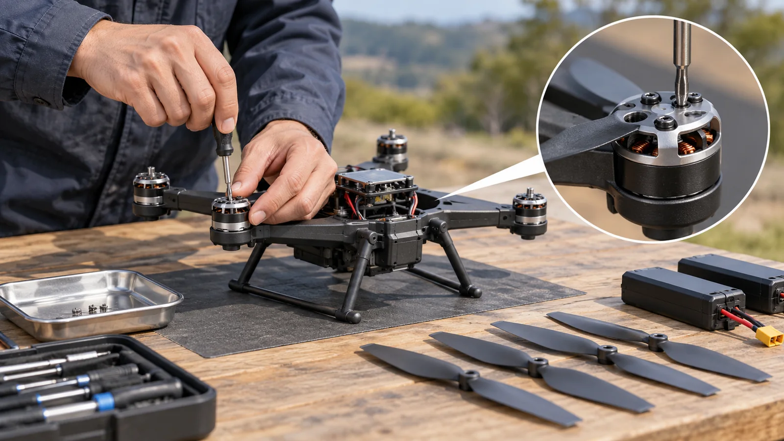
- The short version / what to know first / where this fits in the series
- The condition for floating: thrust against weight
- Steering with four propellers: climb, tilt and heading
- How the parts connect: propellers, motors, ESCs, flight controller, battery
- Checking the power needed with numbers
- The trade-off between battery and flight time
- Airframe materials: not only lightness, but vibration and heat
- Where things stand (checked 25 October 2026)
- How to read the yardsticks and standards
- Glossary / References / Claim-to-source audit
Sourced = stated in a published source (link given)
Our calculation = a value we calculated from stated assumptions
Not yet confirmed = a plan, a target, or research with no confirmed track record
Structural summaries and materials-related readings are marked as “explanation”. Inference is shown in bold. Every analogy comes with its limits.
Flight times, masses and battery capacities are separated into maker-stated values with a source and values we calculated under stated assumptions. A manufacturer’s flight time is a value under conditions the manufacturer sets, such as no payload, no wind and a particular speed, and real use may not match it. Figures of different vehicles are not lined up to rank them. This field changes quickly, so standards and rules carry a check date (25 October 2026). Military and attack equipment is not covered.
1. The short version / what to know first / where this fits in the series
- The condition for floating is “thrust balances weight”. A 1.5 kg drone weighs 1.5 x 9.81 = 14.7 N Our calculation. If the sum of the thrust of four propellers exceeds it, the drone climbs; if equal, it hovers. NASA explains this with simple momentum theory, treating the propeller as a disk that accelerates air backward (downward) and receives the reaction as thrust Sourced[Ref. 1].
- More battery does not add flight time without limit. Adding battery adds weight, and the power needed grows with weight to the power 1.5. In our simple calculation, for a 1.0 kg airframe and payload, flight time peaks at about 25 minutes with a 2.0 kg battery, and adding more battery shortens it Our calculation.
- Airframe material is not decided by lightness alone. In a 7-inch FPV test, motors reached 77.5 C on a carbon-fiber frame, higher than on metal frames (about 50-52 C), and the magnesium frame showed less vibration than aluminum Sourced[Ref. 10].
No prior knowledge is needed. A drone is, like any robot, three things combined: sensing (sensors), thinking (control and intelligence), and moving (actuators). In a multicopter, the inertial sensor (IMU) “senses”, the flight controller “thinks”, and motors and propellers “move”. The single point that “thrust above weight means it floats” is the base of the whole article.
This article is the basics of how a drone flies. For what is inside the battery see our explainers on lithium-ion battery basics and on power sources for robots and drones; for motor magnets see permanent magnets and rare earths; for an overview of frame materials see structural materials for robots and drones; for winged long-endurance aircraft see fixed-wing, VTOL and long-endurance flight; for communication, positioning and collision avoidance see our explainer on those topics; and for national rules see drone regulation and airspace management.
2. The condition for floating: thrust against weight
Hold a drone in your hand and you feel the force pulling it down: its weight (mass x 9.81). To float, the propellers must produce an equal upward force (thrust). If thrust is smaller than weight the drone falls, if equal it hovers in place, and if larger it climbs.
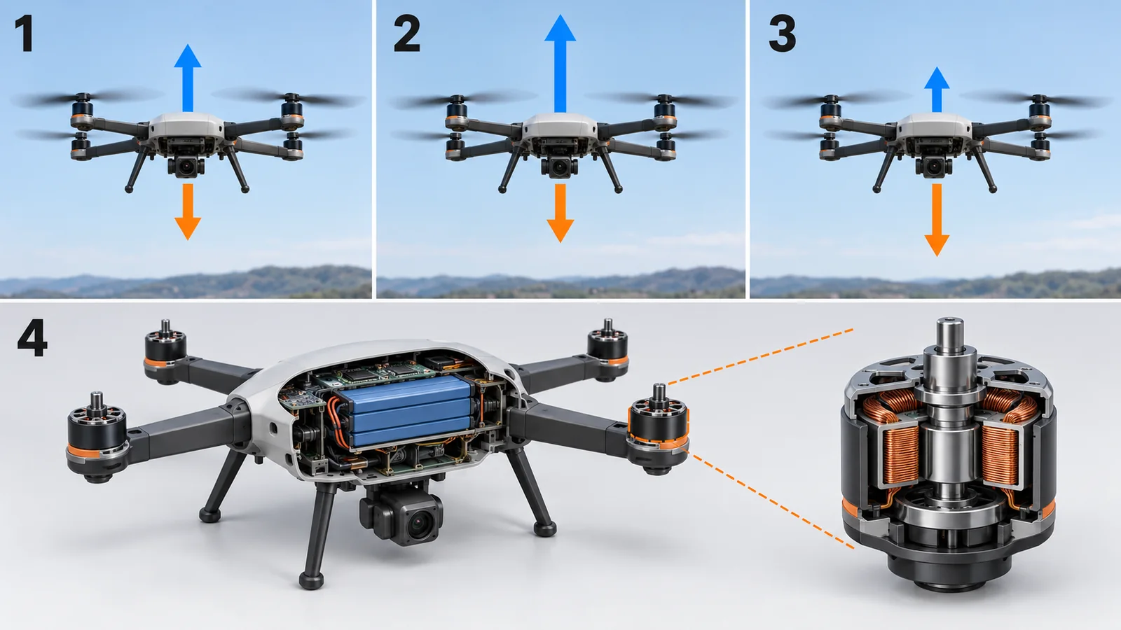
Original SVG, detailed explanation and sources
Original SVG reference: Concept diagram (vector drawing). Concept diagram of the hover condition: hovering when thrust equals weight, climbing above it and sinking below it. An explanatory sketch based on NASA’s momentum-theory description.
A propeller is a “fan” that pushes air down
The thrust of a propeller is the reaction to accelerating air downward. NASA’s explanation uses simple momentum theory, which treats the spinning propeller as “a disk that does work on the air”, and writes thrust as F = 1/2 x rho x A x (Ve^2 – V0^2), where rho is air density, A the disk area, Ve the speed of the air leaving the disk and V0 the speed of the aircraft. This thrust is an ideal value that leaves out real losses such as tip losses Sourced[Ref. 1]. In hover V0 = 0, so F = 1/2 rho A Ve^2.
From this the ideal power (the minimum power needed to push the air) is P = T^1.5 / sqrt(2 rho A), where T is thrust and T = W in hover (our derivation, using the momentum-theory relation that the air speed through the disk is Ve/2) Our calculation. It means two things.
- Power grows with weight to the power 1.5. Doubling the mass multiplies power by 2^1.5 = about 2.83 Our calculation.
- The larger the propeller area, the lower the power. Doubling the area multiplies power by 1 / sqrt(2) = about 0.71 Our calculation. This is the basis of the rule of thumb that large, slowly turning propellers are efficient.
Let us check with numbers. Take a drone of 1.5 kg with four propellers of 12.7 cm radius (10-inch diameter). Thrust is T = 14.7 N and the total disk area is A = 4 x pi x 0.127^2 = 0.203 m2. Ideal power is P = 14.7^1.5 / sqrt(2 x 1.225 x 0.203) = 56.4 / 0.705 = about 80 W Our calculation (rho = 1.225 kg/m3, assumed as standard air density). Real systems need more, because of losses in the propellers, motors and ESCs (Chapter 5).
Thrust is a force (unit N): “how much lifting force there is”. Power is the rate of work (unit W): “how fast energy is used to keep up that force”. Think of a tug of war: how quickly you tire while holding the same pull is the power (limits of the analogy: a real propeller keeps handing energy to the air just to produce force, so it needs power even when stationary). What sets how fast the battery drains is the power.
3. Steering with four propellers: climb, tilt and heading
A multicopter has almost no moving surfaces like wings or rudders. Only the combination of speeds of four or more propellers makes it climb, descend, tilt and turn. The PX4 Guide summarizes multicopters as offering precise hovering and vertical take-off at the cost of shorter, generally slower flight Sourced[Ref. 3].
As the figure shows, neighbouring propellers spin in opposite directions. A spinning propeller makes the body want to turn the other way by reaction, so equal numbers of clockwise and counter-clockwise propellers cancel the twist (explanation). In PX4’s configuration each motor is marked as counter-clockwise or not Sourced[Ref. 7].
The control “brain” is nested. According to the PX4 Guide the controllers are layered: the innermost is the rate controller, then the attitude controller, and the outermost the velocity and position controller. The rate controller matters most, and if it is tuned well the others often need little adjustment Sourced[Ref. 4, 5]. The same guide notes that changing the ESCs or motors changes the best tuning gains Sourced[Ref. 5]: an example of how part compatibility affects control.
When a multicopter is tilted forward, the thrust direction tilts too, and its horizontal component becomes a force forward. It is like holding an umbrella into the wind and being pushed (limits of the analogy: in real flight air drag grows with speed, and tilt and speed settle into balance). To create the tilt, the speeds of front and rear or left and right propellers are made to differ, as in the previous figure.
4. How the parts connect: propellers, motors, ESCs, flight controller, battery
Electric power in a multicopter flows battery to power distribution and ESCs to motors to propellers. Commands flow from sensor and radio signals to the flight controller to the ESCs.
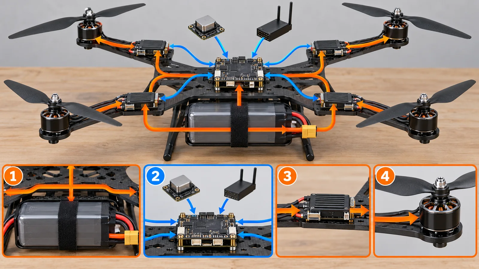
Original SVG, detailed explanation and sources
Original SVG reference: Concept diagram (vector drawing). Power flow from battery, ESCs and motors to propellers, and command flow from the flight controller. A concept diagram of a common layout, not the circuit of a specific product.
- Propeller: the part that makes thrust. Sun et al. (2023) report that propellers with twisted blades gave up to a 9.3% higher efficiency measure (figure of merit) at the same thrust and up to 4.3 dB lower overall sound pressure than untwisted blades Sourced[Ref. 9].
- Motor: turns electricity into rotation, made of magnets and coils. Magnet materials are covered in our explainer on permanent magnets and rare earths.
- ESC (electronic speed controller): turns the battery’s DC into drive power for the motor and sets its speed. The PX4 Guide says the digital DShot protocol has lower latency, is robust through a checksum, needs no ESC calibration, and lets some ESCs return temperature, voltage, current and RPM Sourced[Ref. 6].
- Flight controller: a small computer that estimates attitude and position from sensors (inertial sensors, barometer, GNSS and others) and sends commands to the motors.
- Battery: stores the energy. In NASA’s summary, commercial Li-ion energy cells give 150-270 Wh/kg at an average of 3.6 V, and lithium-polymer (LiPo) cells 150-200 Wh/kg Sourced[Ref. 8]. As a pack, protection circuits, wiring and casing lower the energy per kilogram (explanation).
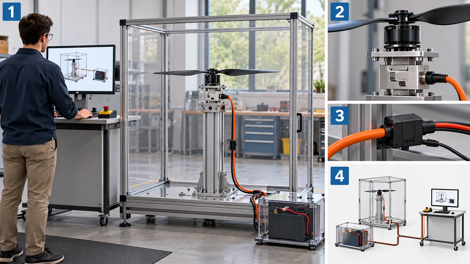
5. Checking the power needed with numbers
The ideal power (P = T^1.5 / sqrt(2 rho A) from Chapter 2) is a lower bound of the real electric power. Let us compare with real vehicles. Bauersfeld and Scaramuzza (2022) give a table of six commercial multicopters with mass, propeller radius, battery and the maker-stated flight time Sourced[Ref. 2]. Using three of them, we back-calculate the average power as the battery’s nominal energy / the maker-stated flight time (assuming 3.7 V per cell and rho = 1.225 kg/m3).
| Vehicle (from the paper’s table) | Mass | Propellers | Battery | Flight time stated by the maker | Ideal power | Real average power | Real / ideal |
|---|---|---|---|---|---|---|---|
| Mavic 2 | 0.91 kg | 4, radius 11.0 cm | 4S1P, 3.9 Ah (about 57.7 Wh) | 31 min | about 44 W | about 112 W | about 2.6x |
| Matrice 200 | 6.14 kg | 4, radius 21.6 cm | 6S2P, 15.3 Ah (about 340 Wh) | 24 min | about 390 W | about 849 W | about 2.2x |
| Matrice 600 Pro | 15.5 kg | 6, radius 26.7 cm | 6S6P, 34.2 Ah (about 759 Wh) | 18 min | about 1,033 W | about 2,531 W | about 2.5x |
Vehicle data and the maker-stated flight times are from the paper’s table (maker values). Ideal power, average power and ratios are Our calculation. “4S1P” is the cell arrangement, four in series and one in parallel. Cell voltage is an assumption (3.7 V per cell) and may differ from the real nominal voltage. Stated flight times are under the manufacturers’ conditions.
For all three, the real average power is about 2.2-2.6 times the ideal power Our calculation. The gap includes propeller losses, motor and ESC losses, onboard electronics such as cameras and radios, and the effect of forward flight; this calculation alone cannot separate them (explanation). Bauersfeld et al. say that their model’s estimates almost always fell within 10% of the manufacturers’ specifications Sourced[Ref. 2].
This is inaccurate. A maker’s flight time changes with payload weight, speed, wind, temperature and battery condition. The stated values in Bauersfeld et al.’s table are set under no-wind, particular conditions, and the paper compares estimates under those conditions [Ref. 2]. From the weight-to-the-1.5 relation above, adding payload shortens flight time more than expected (for example, a 20% mass increase raises required power by 1.2^1.5 = about 1.31 times) Our calculation.
6. The trade-off between battery and flight time
“To fly longer, make the battery bigger” is the natural idea. But adding battery adds weight and raises the power needed. Here we estimate, with a simple model, flight time as battery mass mb is added to an airframe plus payload of mass m0 = 1.0 kg. The assumptions are:
- Total rotor area is fixed at 0.2 m2 (in reality heavier aircraft need bigger rotors).
- Overall efficiency eta = 0.4 (based on the “ideal / real” of about 0.39-0.46 for the three vehicles in Chapter 5).
- Battery 150 Wh/kg at pack level (aligned with the low end of NASA’s 150-200 Wh/kg for LiPo cells) and 80% usable.
Flight time is then t = 0.8 x 150 x mb / (P_ideal / 0.4), where P_ideal = T^1.5 / sqrt(2 rho A) and T = (1.0 + mb) x 9.81. The calculation gives about 16 minutes at mb = 0.4 kg, about 23 minutes at 1.0 kg, about 25 minutes (the maximum) at 2.0 kg, about 25 minutes at 3.0 kg and about 24 minutes at 4.0 kg Our calculation. The peak occurs when the battery mass is twice the airframe plus payload (mb = 2 x m0), because t is proportional to mb / (m0 + mb)^1.5, which is largest at mb = 2 m0 Our calculation.
This is wrong. Doubling the battery makes the drone heavier and raises the power needed. In the example above, doubling the battery from 0.4 kg to 0.8 kg raises flight time from about 16 to about 22 minutes, only about 1.4 times Our calculation. A battery is among the heaviest parts of a drone, and this is where higher-energy-density batteries (see our explainers on lithium-ion battery basics and next-generation energy storage) earn their value. The model here is simple, though, and the best battery share in a real design depends on the design.
Flight time t is proportional to battery energy density e. If the battery goes from 150 to 300 Wh/kg, the same drone’s flight time approaches double (within this model, and ignoring changes in weight) Our calculation. In NASA’s summary commercial Li-ion cells are 150-270 Wh/kg, and in laboratory and high-altitude use some approach 450-500 Wh/kg Sourced[Ref. 8]. From the materials side, raising a cell’s Wh/kg by changing electrode, electrolyte and separator materials links directly to drone flight time. But pack-level Wh/kg is lower by the weight of protection circuits and casing (our explanation).
7. Airframe materials: not only lightness, but vibration and heat
Frame materials are often assumed to be “the lighter the better”. But a material decides weight, strength, how vibration travels, how heat escapes, impact resistance and cost at once. Here are three recent studies.
Metal versus carbon fiber: vibration and heat (Milenin, 2026)
Milenin compared a 7-inch FPV frame in cast AZ31 magnesium alloy, 6061-T6 aluminum and carbon-fiber (CF) composite. At a 2 kg payload the magnesium frame had 49% less vibration power than the aluminum one, with resonance peaks at 147 Hz (0 kg) and 204 Hz (2 kg) for magnesium and at 179.5 Hz and 239.4 Hz for aluminum. Average motor temperature was 51.8 C on magnesium and 50.3 C on aluminum, against 77.5 C on carbon fiber Sourced[Ref. 10]. The author says magnesium offers an excellent combination of light stiffness and damping and suits heavy-duty platforms. These are results for one frame under particular conditions, not a general ranking of materials.
3D-printed PETG with carbon fiber: infill pattern changes performance (Palaniappan et al., 2026)
When PETG (polyethylene terephthalate glycol) with carbon fiber is made by fused deposition modeling, the internal infill pattern decides performance. Five of 21 patterns were tested for tension, wear, impact and hardness: rectilinear infill gave a tensile strength of 35 N/mm2, and Support Cubic an impact energy of 6.5 J (more than 60% above the other patterns). A frame made with Support Cubic survived a 12 m (23.5 J) drop, exceeding the failure threshold of a conventional carbon frame, as reported Sourced[Ref. 11].
Resonance: propeller rotation versus the airframe’s natural frequency
Propeller rotation gives the airframe periodic vibration. When the excitation frequency matches the airframe’s natural frequency, it resonates, sensors are disturbed and handling degrades. Tullu et al. (2018) showed how to optimize the dimensions, stiffness and mounting position of arms and landing gear so that the lowest natural frequency stays above the propellers’ maximum excitation frequency Sourced[Ref. 12].
Carbon-fiber composite is the standard “light and stiff” material, but in Milenin’s test motor heat escaped poorly and temperatures rose [Ref. 10]. Metal conducts heat and can help cool the motors, but is denser and so heavier for the same volume. That a light metal such as magnesium has damping that attenuates vibration also matters for protecting sensors. Material choice is a trade-off among density, stiffness, thermal conductivity, damping, impact, workability and cost (our explanation; materials in more detail are in our explainer on structural materials for robots and drones).
Not necessarily. Carbon fiber is light and stiff, but it can trap heat, can crack under impact and takes effort to make. An optimized 3D-printed PETG-carbon-fiber frame is reported to have survived a drop above the failure threshold of a conventional carbon frame [Ref. 11], while the high motor temperatures appeared on the carbon-fiber frame in Milenin’s test above [Ref. 10]. The best material changes with the use (endurance, heavy payload, how often it is dropped, cost).
8. Where things stand (checked 25 October 2026)
This field changes quickly, so here is what could be confirmed from primary sources, with check dates.
| Item | What was confirmed | Label |
|---|---|---|
| Principle of floating and thrust formula | The momentum-theory thrust formula (an ideal value) [Ref. 1] | Sourced |
| Control structure | PX4 uses nested rate, attitude and velocity/position control; DShot ESC communication [Ref. 4, 5, 6] | Sourced |
| Estimating flight time | A paper’s model fell within about 10% of the manufacturers’ stated values for six commercial vehicles [Ref. 2] | Sourced |
| Batteries | Commercial Li-ion cells 150-270 Wh/kg and LiPo cells 150-200 Wh/kg (NASA’s summary) [Ref. 8] | Sourced |
| Airframe materials | On a 7-inch FPV frame, lower vibration with magnesium and higher motor temperature with carbon fiber (2026). An optimized 3D-printed PETG-carbon-fiber frame survived a 12 m drop (2026) [Ref. 10, 11] | Sourced |
| Standards and rules | ISO 21895:2026 (September 2026), ISO 21384-3:2026 (August 2026) and others. Japan requires registration for 100 g and above [Ref. 13, 15, 18] | Sourced |
| Real values of rotor area, efficiency and battery density; measured flight times; life and cost by material | Could not be confirmed within this article’s research (our calculations use assumptions) | Not yet confirmed |
Checked 25 October 2026.
A multicopter floats when thrust balances weight, and steers climb, tilt and heading through the combination of speeds of four or more propellers. The power needed grows with weight to the power 1.5 and falls as propeller area grows. Real average power was about 2.2-2.6 times the ideal power. Adding battery makes flight time level off; in our simple model the maximum came with a battery twice the airframe plus payload. Airframe materials are chosen not only for lightness but for vibration, heat and impact, and a higher-energy-density battery is the key to flight time.
9. How to read the yardsticks and standards
The quality of a multicopter cannot be measured by one number. There are several yardsticks: flight time (hovering or moving), maximum take-off mass and payload, top speed, wind tolerance, noise, vibration and reliability, and their meaning changes with payload weight, speed, temperature and battery condition. The table shows what each measures and does not measure, as far as could be confirmed.
| Item | Representative tests / benchmarks (name, source) | Standards, rules, guidance (ISO, MLIT and others) | Cautions when reading |
|---|---|---|---|
| Flight time and range | Maker-stated (conditions set by the maker). A paper’s model is within about 10% for six vehicles [Ref. 2] Sourced | A unified international standard fixing how to measure flight time could not be confirmed within this article’s research | Check conditions such as no payload, no wind and speed. It is sensitive to payload through the 1.5 power of weight |
| Classification of aircraft | – | ISO 21895:2026 “Categorization and classification of civil uncrewed aircraft systems” (Published, September 2026; the 2020 edition is in withdrawal; full text paid and not read) [Ref. 13] Sourced | Classification is likely used as the “scope of application” for rules and tests (inference). Text not read, so the content of grades is not described |
| Quality and safety of components | – | ISO 21384-2:2021 “Unmanned aircraft systems — Part 2: UAS components” (Published, December 2021; text not read) [Ref. 14] Sourced | Requirements not read |
| Operational procedures | – | ISO 21384-3:2026 “Uncrewed aircraft systems — Part 3: Operational procedures” (Published, August 2026; safe commercial operations; text not read) [Ref. 15] Sourced | A standard for commercial operations. National rules separately apply to hobby flying |
| Vibration | Design against airframe resonance (Tullu et al.), vibration measurement (Milenin) [Ref. 12, 10] Sourced | ISO 5309:2023 “Civil small and light unmanned aircraft systems (UAS) — Vibration test methods” (Published, December 2023; test conditions and methods for levels II-V; text not read) [Ref. 17] Sourced | Test conditions and pass criteria not read. Research results and the standard’s tests are different things |
| Terminology | – | ISO 21384-4:2025 “Uncrewed aircraft systems — Part 4: Vocabulary” (Published, July 2025) [Ref. 16] Sourced | Definitions of terms, not requirements |
| Registration and identification (Japan) | – | MLIT: unmanned aircraft of 100 g or more flown outdoors must be registered, display a registration mark and have Remote ID [Ref. 18] Sourced | A legal duty. Rules differ by country; see our explainer on drone regulation and airspace management |
The arrangement of the table is Our calculation (organization). The ISO texts are paid and were not read, so only titles, scope and status are given. No ASTM International standard or website was consulted.
Cautions when reading (for materials engineers)
- Demonstrations, benchmarks and the field are different. A maker-stated flight time or a laboratory thrust test does not show results in the field, with wind, temperature and payload.
- Maker-stated values and third-party verification are different. A maker-stated value is a value under the maker’s conditions. The model in Bauersfeld et al. was validated against stated values, which is not the same as measurement in real use.
- A standard is a “reference frame”, not law itself. The ISO texts were not read. A duty such as registration is a national rule (inference).
- Plans and achievements are different. The test result of a new battery or material is for one vehicle and condition and does not show the effect on every vehicle.
10. Glossary
- Multicopter
- A rotorcraft that flies on four or more propellers and is steered by their speeds alone.
- Thrust
- The upward force a propeller produces. Unit: N.
- Weight
- Mass x 9.81, the downward pull.
- Hover
- Floating still in place. Thrust = weight.
- Power
- The rate of work. Unit: W. It sets how fast the battery drains.
- Momentum theory
- A simple theory treating a propeller as a disk that accelerates air, to find thrust.
- Ideal (induced) power
- The minimum power needed to push the air. Excludes losses.
- Figure of merit
- A propeller efficiency measure: ideal power divided by actual power.
- ESC
- Electronic speed controller: the circuit that sets motor speed.
- DShot
- A digital protocol connecting the flight controller and ESCs.
- Flight controller
- A small computer that estimates attitude from sensors and commands the motors.
- IMU
- An inertial sensor measuring acceleration and rotation.
- GNSS
- The general name for satellite positioning (GPS and others).
- Rate controller
- The innermost control layer, matching the speed of the craft’s rotation.
- Yaw
- Turning the heading (rotation seen from above).
- LiPo / lithium-ion
- Rechargeable batteries widely used in drones, with high energy per kilogram (Wh/kg).
- 4S1P
- Four cells in series, one string. Voltage is four times a cell’s, capacity that of one string.
- Energy density (Wh/kg)
- Energy stored per kilogram of battery.
- Resonance
- Vibration grows when the excitation frequency matches the natural frequency.
- FPV
- First-person view: flying while watching the aircraft’s camera image.
- Infill pattern
- The internal fill shape in 3D printing; it affects strength and weight.
11. References
- NASA Glenn Research Center “Propeller Thrust” (thrust from simple momentum theory, F = 1/2 rho A (Ve^2 – V0^2); updated 13 May 2021; checked 25 October 2026) — grc.nasa.gov/www/k-12/airplane/propth.html
- Bauersfeld L., Scaramuzza D. “Range, Endurance, and Optimal Speed Estimates for Multicopters”, IEEE Robotics and Automation Letters 7(2), 2022 (text and table read on arXiv:2109.04741) — doi.org/10.1109/LRA.2022.3145063
- PX4 Guide “Basic Concepts” (characteristics of multicopters; checked 25 October 2026) — docs.px4.io/main/en/getting_started/px4_basic_concepts.html
- PX4 Guide “Controller Diagrams” (nested multicopter control; checked 25 October 2026) — docs.px4.io/main/en/flight_stack/controller_diagrams.html
- PX4 Guide “Multicopter PID Tuning Guide (Manual/Basic)” (layered rate, attitude and velocity/position control; ESCs and motors change the best tuning; checked 25 October 2026) — docs.px4.io/main/en/config_mc/pid_tuning_guide_multicopter_basic.html
- PX4 Guide “DShot ESCs” (digital ESC protocol and telemetry; checked 25 October 2026) — docs.px4.io/main/en/peripherals/dshot.html
- PX4 Guide “Actuator Configuration and Testing” (motor positions and spin directions; checked 25 October 2026) — docs.px4.io/main/en/config/actuators.html
- NASA “State-of-the-Art of Small Spacecraft Technology, 3.0 Power” (commercial Li-ion cells 150-270 Wh/kg; LiPo cells 150-200 Wh/kg; checked 25 October 2026) — nasa.gov/smallsat-institute/sst-soa/power-subsystems/
- Sun Y. et al. “Blade Twist Effects on Aerodynamic Performance and Noise Reduction in a Multirotor Propeller”, Drones 7(4), 252 (2023) — doi.org/10.3390/drones7040252
- Milenin A. “Experimental Analysis of an AZ31 Magnesium Alloy Structural FPV Drone Frame: Comparison with Aluminum and Carbon Fiber”, Processes 14(9), 1361 (2026) — doi.org/10.3390/pr14091361
- Palaniappan S. K. et al. “Mechanical characterization of PETG – carbon fiber composite parts using 3D printing for drone frame application”, Scientific Reports 16, 6938 (2026) — doi.org/10.1038/s41598-026-38051-3
- Tullu A. et al. “Parameter optimization to avoid propeller-induced structural resonance of quadrotor type Unmanned Aerial Vehicle”, Composite Structures 193, 63-72 (2018) — doi.org/10.1016/j.compstruct.2018.03.014
- ISO ISO 21895:2026 “Categorization and classification of civil uncrewed aircraft systems” (ISO page; Published, September 2026; the 2020 edition is in withdrawal; full text paid and not read; checked 25 October 2026) — iso.org/standard/91003.html
- ISO ISO 21384-2:2021 “Unmanned aircraft systems — Part 2: UAS components” (ISO page; Published, December 2021; text not read; checked 25 October 2026) — iso.org/standard/80123.html
- ISO ISO 21384-3:2026 “Uncrewed aircraft systems — Part 3: Operational procedures” (ISO page; Published, August 2026; text not read; checked 25 October 2026) — iso.org/standard/88660.html
- ISO ISO 21384-4:2025 “Uncrewed aircraft systems — Part 4: Vocabulary” (ISO page; Published, July 2025; checked 25 October 2026) — iso.org/standard/85053.html
- ISO ISO 5309:2023 “Civil small and light unmanned aircraft systems (UAS) — Vibration test methods” (ISO page; Published, December 2023; text not read; checked 25 October 2026) — iso.org/standard/81112.html
- Ministry of Land, Infrastructure, Transport and Tourism (MLIT) MLIT unmanned aircraft information portal (in Japanese; registration, marking and Remote ID for outdoor unmanned aircraft of 100 g or more; checked 25 October 2026) — mlit.go.jp/koku/info/index.html
12. Claim-to-source audit
| Claim in the text | Basis | Label |
|---|---|---|
| Simple momentum theory for propeller thrust (F = 1/2 rho A (Ve^2 – V0^2)); an ideal value that excludes losses such as tip losses | NASA Glenn explanation Reference 1 https://www.grc.nasa.gov/www/k-12/airplane/propth.html | Sourced |
| A study estimating multicopter range, endurance and optimal speed from blade-element-momentum theory with motor and battery models; the table of six commercial vehicles (Mavic 2: 0.91 kg, 11.0 cm radius, 4S1P 3.9 Ah, 31 min stated; Matrice 200: 6.14 kg, 21.6 cm, 6S2P 15.3 Ah, 24 min; Matrice 600 Pro: 15.5 kg, 6 x 26.7 cm, 6S6P 34.2 Ah, 18 min); estimates almost always within 10% of the stated values | Abstract and table of Bauersfeld and Scaramuzza (2022) (maker-stated values) Reference 2 https://doi.org/10.1109/LRA.2022.3145063 | Sourced |
| Characteristics of multicopters (precise hovering and vertical take-off at the cost of shorter, slower flight); nested control (rate, attitude, velocity and position) with the rate loop most important; ESCs and motors changing the best tuning gains; DShot ESC communication and ESCs returning telemetry (temperature, voltage, current, RPM); per-motor spin direction (CW or CCW) | Four PX4 Guide pages Reference 3 https://docs.px4.io/main/en/getting_started/px4_basic_concepts.html Reference 4 https://docs.px4.io/main/en/flight_stack/controller_diagrams.html Reference 5 https://docs.px4.io/main/en/config_mc/pid_tuning_guide_multicopter_basic.html Reference 6 https://docs.px4.io/main/en/peripherals/dshot.html Reference 7 https://docs.px4.io/main/en/config/actuators.html | Sourced |
| Commercial Li-ion energy cells at 150-270 Wh/kg with an average of 3.6 V, and LiPo cells at 150-200 Wh/kg | NASA small-spacecraft technology report Reference 8 https://www.nasa.gov/smallsat-institute/sst-soa/power-subsystems/ | Sourced |
| Propellers with twisted blades gave up to a 9.3% higher figure of merit at the same thrust and up to 4.3 dB lower overall sound pressure level than untwisted blades | Abstract of Sun et al. (2023) Reference 9 https://doi.org/10.3390/drones7040252 | Sourced |
| Comparison of 7-inch FPV frames (cast AZ31 magnesium, 6061-T6 aluminum, carbon fiber): at 2 kg payload magnesium had 49% less vibration power than aluminum, resonance peaks, and average motor temperatures (magnesium 51.8 C, aluminum 50.3 C, carbon fiber 77.5 C) | Abstract of Milenin (2026) Reference 10 https://doi.org/10.3390/pr14091361 | Sourced |
| 3D-printed PETG with carbon fiber: five of 21 infill patterns shortlisted, rectilinear infill at 35 N/mm2 tensile strength, Support Cubic at 6.5 J impact energy, and an optimized frame surviving a 12 m (23.5 J) drop, above the failure threshold of a conventional carbon frame | Abstract of Palaniappan et al. (2026) Reference 11 https://doi.org/10.1038/s41598-026-38051-3 | Sourced |
| Resonance between propeller excitation and the structure’s natural frequency degrades sensors; design raises the lowest natural frequency above the maximum excitation (arm and leg dimensions and stiffness) | Abstract of Tullu et al. (2018) Reference 12 https://doi.org/10.1016/j.compstruct.2018.03.014 | Sourced |
| Titles, scope and status of ISO 21895:2026 (categorization and grading; published September 2026; the 2020 edition in withdrawal), ISO 21384-2:2021 (components), ISO 21384-3:2026 (operational procedures; August 2026), ISO 21384-4:2025 (vocabulary) and ISO 5309:2023 (vibration test methods) | Five ISO pages Reference 13 https://www.iso.org/standard/91003.html Reference 14 https://www.iso.org/standard/80123.html Reference 15 https://www.iso.org/standard/88660.html Reference 16 https://www.iso.org/standard/85053.html Reference 17 https://www.iso.org/standard/81112.html | Sourced |
| All unmanned aircraft of 100 g or more flown outdoors must by law be registered, display a registration mark and have Remote ID | MLIT portal for unmanned aircraft Reference 18 https://www.mlit.go.jp/koku/info/index.html | Sourced |
| Required thrust T = mass x 9.81; ideal induced power P = T^1.5 / sqrt(2 rho A) (derived from NASA’s expression for hover with V0 = 0 and a disk velocity of Ve/2); ideal versus actual average power for three vehicles (43.7 W / 112 W, 390 W / 849 W, 1,033 W / 2,531 W; assuming 3.7 V per cell and rho = 1.225 kg/m3); the flight-time model (m0 = 1.0 kg, A = 0.2 m2, eta = 0.4, 150 Wh/kg, 80%; peak of about 25 minutes at a 2.0 kg battery); and the optimum at mb = 2 x m0 | Our own calculation (assumptions stated in the text and figures) | Our calculation |
| Assumed rotor area, overall efficiency and battery energy density, actual design values of specific vehicles, measured flight times, life and cost by airframe material, and details of national rules such as the US FCC and FAA are not given because they could not be confirmed within this article’s research (or are out of scope) | The scope of research for this article | Explanation |
| The thrust-versus-weight contest, the basic combinations of four propellers, the connection of parts, the analogies (a fan pushing air down, a tug of war), the materials-engineer notes, and the fact that the figures are explanatory drawings or frames | This article’s explanation (our reading of the sourced facts) | Explanation |
Last updated: 25 October 2026. Sources are limited to primary material (NASA Glenn and PX4 Guide technical documents, a NASA battery report, papers in IEEE RA-L, Processes, Scientific Reports, Composite Structures and Drones, ISO pages and Japanese MLIT material). Maker-stated values are labeled as such and kept separate from independent verification. The worked examples (ideal power, average power, the flight-time model) are our own explanatory calculations and not design values of any vehicle. Real values of rotor area, efficiency and battery density, measured flight times, life and cost by material, and details of national rules could not be confirmed (or are out of scope) and are therefore not given. All figures are explanatory concept diagrams or drawings with our own calculations, except Figs. 1 and 5, which are ImageGen-generated conceptual illustrations. They do not depict real vehicles, equipment or appearances.