TECHNOLOGY EXPLAINER
Structural Materials for Robots and Drones
– Where does “light and stiff” actually come from?
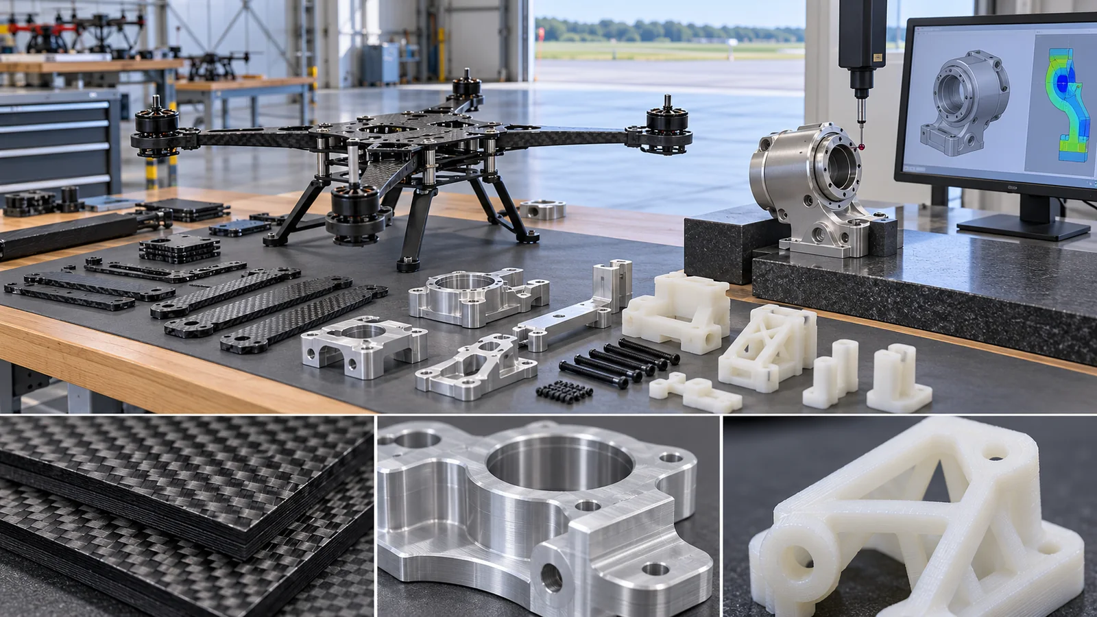
A drone eats battery in proportion to its weight. A robot arm needs bigger motors the heavier it is. So the structure must be both light and stiff. Yet among metals, stiffness per unit mass (specific stiffness) is almost the same; the difference appears when carbon fiber is used. And carbon-fiber composites bring quirks that matter in design: stiffness depends on direction, they shed heat poorly, and they block radio waves. This article compares aluminum, magnesium, titanium, CFRP, engineering plastics and 3D-printed materials using manufacturers’ data sheets and numbers from papers, and explains in figures what materials engineers should notice. Light-weight materials for spacecraft are left to other articles in this series; here we stay with the airframes of drones and the bodies of robots.
- What a structure must do (the short version)
- Why mass matters so much
- Yardsticks for materials: specific stiffness and equal-mass beam stiffness
- Carbon-fiber composites: stiffness depends on direction
- Metals: aluminum, magnesium, titanium; fatigue and galvanic contact
- Materials also steer heat and radio waves
- Plastics and 3D printing: build direction and heat resistance
- Limits, what we could not confirm, and a summary
- How to read the yardsticks and standards
- Glossary
- References (primary sources)
- Claim-to-source audit
Sourced = stated in a published source (linked)
Our calculation = our own calculation or arrangement using published values (assumptions are stated)
Not yet confirmed = plans, standards under revision or work in progress that is not settled
Inference is shown in bold. Readings that have no source are marked “commentary”.
Material numbers are typical values from manufacturers (company’s stated values) or values from a specific paper under its test conditions. They are not guaranteed design values (the data sheets themselves say so). We do not rank different materials or aircraft by their numbers. This field moves fast, so the state of standards and documents is as of the check date (25 October 2026). We give no individual safety or legal advice.
1. What a structure must do (the short version)
- The frame must be light, stiff and hard to break: a drone’s airframe must cut the weight that sets its flight time, yet be stiff enough that vibration neither breaks it nor upsets control. A robot arm needs bigger motors the heavier it is.
- Among metals, stiffness per unit mass is nearly the same: the “elastic modulus divided by density” of aluminum, titanium and magnesium all come out at about 24 to 25. The difference comes from carbon-fiber composites (CFRP), but their stiffness changes strongly with direction Our calculation.
- Materials also affect heat and radio: papers have measured that carbon-fiber airframes shed motor heat poorly and block radio waves. Choosing only for “light and strong” causes trouble elsewhere.
In this series a robot is a combination of three things: “sense” (sensors), “think” (control and intelligence) and “move” (actuators). A drone is the same. The star of this article is something that belongs to none of them: the body (structure). The elastic modulus (Young’s modulus) is a measure of stiffness when pulled; a larger value means the material deforms less. Density is the mass per cubic centimeter.
Where this fits in the series: this article covers the materials of whole drone and robot bodies. The map of light metals (aluminum-lithium alloys, titanium and so on), the basics of carbon fiber and the effects of the space environment are covered in the space-industry explainers on lightweight structural materials and on space CFRP and composites, and in the polymers explainer on CFRP and composite materials, so here we refer only to the key points, without repeating them. Batteries are in our explainer on power sources for robots and drones, and joint drives in the one on joint actuators.
Figure 2 divides a drone and a robot arm into parts. Each part needs different things.

Original SVG, detailed explanation and sources
Original SVG reference: Concept diagram (vector drawing). Our arrangement of example materials and requirements for each part of a drone and a robot arm. The materials are examples of options, not the make-up of any specific machine or product. The materials the UR5e data sheet lists are “aluminum, plastic, steel” [Ref. 15].
2. Why mass matters so much
Drones: weight acts on power to the power of 1.5
When a drone hovers, the propellers keep producing a thrust equal to the aircraft’s weight. From propeller theory (momentum theory), the power needed to hover is proportional to the 1.5th power of the aircraft’s mass. Bauersfeld and Scaramuzza give this relationship as an equation in their multicopter model (hover power proportional to (mg)3/2) [Ref. 1] Sourced.
Let us check what the 1.5th power means with numbers. If total mass falls 5%, power falls to 0.951.5 = 0.926 times, about 7.4% less Our calculation (Fig. 3, left). With the same battery, flight time would in theory rise by about 8.0% Our calculation (1 / 0.926 = 1.080, assuming the battery mass and the aircraft’s efficiency do not change). For example, suppose a 1 kg drone has a 0.25 kg frame. Making the frame 20% lighter saves 0.05 kg, which is 5% of the total Our calculation (an illustrative assumption).
Robot arms: weight acts on torque
Robot arms also benefit from being light. With the arm held horizontal, the shoulder joint feels a turning force (torque) from the arm’s weight. If a 5 kg link has its center of mass 0.5 m from the shoulder, the torque is 5 x 9.81 x 0.5 = about 24.5 N·m Our calculation. If the link can be 4 kg, it is 19.6 N·m, about 20% less Our calculation (Fig. 3, right). If the shoulder drive can be smaller, the whole arm gets lighter still – a virtuous circle we can hope for (Inference).
If mass doubles, power does not double but rises by 21.5 = about 2.8 times. A way to picture it: to hold up more weight, the propellers must spin faster or be larger, and that raises power steeply (a comparison: carrying a heavy load tires you out sharply even at the same walking speed. The comparison’s limit: real power also includes motor and battery losses). The numbers here are the ideal power with losses removed [Ref. 1].
The Universal Robots UR5e data sheet gives a payload of 5 kg, a reach of 850 mm, a mass of 20.6 kg including cable and the materials “aluminum, plastic, steel” (company’s stated values) [Ref. 15] Sourced. Dividing payload by mass gives 5 / 20.6 = about 0.24 Our calculation. This is a guide for this robot under its conditions, not a ranking against other robots.
3. Yardsticks for materials: specific stiffness and equal-mass beam stiffness
The yardstick that turns “light and stiff” into a number is specific stiffness: the elastic modulus E divided by the density rho (E/rho), a guide to stiffness per gram of material. Table 1 collects numbers from data sheets and papers.
| Material (source) | Density rho [g/cm³] | Elastic modulus E [GPa] | E/rho | Yield and tensile strength [MPa] |
|---|---|---|---|---|
| Aluminum 6061-T6 (Kaiser, typical values for extruded rod and bar) [2] | 2.70 | 68.3 | 25.3 | yield 276 / tensile 310 (elongation 17%) |
| Titanium Ti-6Al-4V ELI, annealed (Aubert & Duval, typical values) [3] | 4.42 | 110 | 24.9 | yield 790 / tensile 860 (elongation 10%) |
| Magnesium AZ31 (mean of NASA KSC tensile tests, apparent E) [4]. Density is that of pure magnesium [5] | 1.74 | 42.0 | 24.1 | yield 206 / tensile 294 (elongation 15%) |
| CFRP unidirectional 0 deg (IM7/8552, Hexcel, 25 °C, dry) [6] | 1.57 (laminate) | 164 | 104.5 | 0 deg tensile strength 2724 |
| CFRP unidirectional 90 deg (same) [6] | 1.57 | 12 | 7.6 | 90 deg tensile strength 64 |
| CFRP quasi-isotropic [0/45/-45/90]s (our calculation) | 1.57 | 62.7 | 39.9 | – (strength not calculated) |
| PA12 (laser sintered, EOS PA 2200 Balance, X direction) [13] | 0.93 | 1.65 | 1.8 | tensile 48 (elongation 18%) |
The numbers in each row are typical values from manufacturers and papers Sourced. The E/rho column and the quasi-isotropic row are Our calculation (division, and the calculation in Chapter 4). The 90 deg strength is Hexcel’s IM7 value (64 MPa). The T6 yield and tensile values are for a 0.500 inch diameter specimen (Kaiser).
The table shows that aluminum (25.3), titanium (24.9) and magnesium (24.1) have almost the same E/rho Our calculation. So “titanium is light and strong, therefore stiff” does not hold; titanium’s strength is in its strength (yield) (we do not compare yield per density here). Pulled along the fibers, CFRP has an E/rho of about 104, a little over four times that of the metals Our calculation.
For the same mass, which bends least?
In a frame, materials are made into plates and bars. If you make a bar of the same weight, a lighter material can make it thicker. A thicker bar bends less (bending stiffness goes with the fourth power of thickness). Including this effect changes how materials compare. Take a beam with a square cross-section of side b and length L; the stiffness k for a force at its tip is k = 3EI/L³ with I = b⁴/12. Holding the mass m = rho b² L fixed gives k proportional to E/rho² Our calculation (derivation in “More detail” below).
More detail: why E/rho² appears
A cantilever (a bar fixed at one end) with a force F at its tip deflects by delta = FL³/(3EI). The stiffness is k = F/delta = 3EI/L³. For a square cross-section of side b, the second moment of area is I = b⁴/12, so k = Eb⁴/(4L³). Since the mass is m = rho b² L, b² = m/(rho L), and b⁴ = m²/(rho L)². Substituting gives k = E·m²/(4 rho² L⁵). With m and L fixed, k is proportional to E/rho².
This assumes the cross-section can be scaled up in a similar shape. Real thin-walled tubes are limited by buckling (thin walls wrinkle), by the minimum practical thickness and by joint strength. The expression is a guide for comparing materials, not a design conclusion (our commentary).
As Fig. 4 (right) shows, for equal mass, magnesium (13.9) is about 1.5 times aluminum (9.4) Our calculation, titanium (5.6) is about 0.6 times aluminum Our calculation, quasi-isotropic CFRP (25.4) is about 2.7 times Our calculation, and 0 degree unidirectional CFRP (66.5) is about 7 times Our calculation. Even with a smaller E, magnesium is lighter and so can be made thicker, which makes it bend less at equal mass. But the magnesium E used here is the apparent value from a NASA internship report and was not checked against another source (not confirmed).
The elastic modulus of a metal is set mostly by the strength of the bonds between atoms, so alloying to raise strength hardly changes E/rho (commentary). In Table 1, aluminum, titanium and magnesium are all about 24 to 25. Strength (yield) changes a great deal with alloy and heat treatment. For example, in the Aubert & Duval data sheet for steel 819B, the same steel has yield strengths of 850 MPa and 1400 MPa depending on tempering temperature [Ref. 29] Sourced (no elastic modulus is given). So lightening a metal part is mainly a matter of shape – getting the same stiffness with thin walls and hollow sections – and what the material itself contributes is strength (fatigue, impact). A carbon-fiber composite, by contrast, raises E/rho itself by aligning the high-stiffness fibers with the load.
4. Carbon-fiber composites: stiffness depends on direction
A carbon-fiber composite (CFRP) is fine fibers set in resin. The basics of making fibers and of molding methods are in the polymers explainer on CFRP and composite materials. Here we stick to what matters in robot and drone design: the dependence of stiffness on direction (anisotropy).
The Toray data sheet for T700S carbon fiber gives the fiber itself a tensile strength of 4,900 MPa, a tensile modulus of 230 GPa and a density of 1.80 g/cm³ [Ref. 7] Sourced. Set in epoxy at 60% fiber volume, the composite has a tensile strength of 2,860 MPa and a modulus of 134 GPa [Ref. 7] Sourced. Pulled across the fibers, however, the strength (90 degree tensile strength) is 81 MPa [Ref. 7] Sourced. Across the fibers the strength is about 1/35 Our calculation (81 / 2860).
As Fig. 5 shows, the modulus falls from 164 GPa along the fibers (0 degrees) to about 55.7 GPa, roughly one third Our calculation, with only a 15 degree turn. At 45 degrees it is 14.0 GPa and at 90 degrees 12 GPa, about 1/14 of the fiber-direction value Our calculation. Stacking layers at different angles (laminating) gives a “quasi-isotropic” laminate with similar stiffness in every in-plane direction, but its modulus is about 62.7 GPa, about 38% of the unidirectional 0 degree value (164 GPa) Our calculation. A statement like “carbon fiber is so many times stiffer than steel” means nothing until you check which direction and which lay-up the value is for.
Claims of this kind compare the tensile strength of the fiber itself (4,900 MPa for T700S) with the value for a metal [Ref. 7]. Once made into a composite, the value falls with the fraction of fibers (2,860 MPa at 60%), and across the fibers it drops to 81 MPa [Ref. 7] Sourced. The correct reading: “extremely light, stiff and strong – but only when pulled along the fibers”. Bending, twisting, impact and joints need different design (see the polymers explainer on CFRP and composite materials).
Think of a bundle of drinking straws. Bundled in the same direction, they resist a lengthwise pull with the strength of the straws themselves. Pulled sideways, only the strength of the glue between the straws counts. In CFRP too, the fibers carry the load and the resin holds them together, so the further the load is from the fiber direction, the more the resin’s weakness shows (the comparison’s limit: real fibers are far thinner than straws and are bonded to the resin through an interface).
5. Metals: aluminum, magnesium, titanium; fatigue and galvanic contact
Metal frame parts are made by machining, casting and sheet-metal work. Aluminum is commonly used for the motor mounts of drones and the joint housings of robots (commentary; that aluminum is among the UR5e’s materials is sourced [Ref. 15]). Magnesium bends less at equal mass (Fig. 4, right), and cast frames have been studied (next chapter). Titanium has high strength (yield 790 MPa, Table 1) and suits small parts that must be light and also strong (commentary).
Fatigue: “never yielding” is not enough
The airframes of drones and the joints of robots can suffer fatigue (failure under repeated loads even below the yield strength) from propeller vibration and repeated motion. The Kaiser data sheet gives the “fatigue endurance limit” of 6061-T6 (the stress it survives for 5 x 10⁸ cycles of reversed stress in an R.R. Moore test) as 97 MPa [Ref. 2] Sourced. That is about 35% of the 276 MPa yield strength Our calculation and about 31% of the 310 MPa tensile strength Our calculation. Designing as if “use up to the yield strength” is allowed would fall short under repeated loading (values vary with test method, surface condition and environment).
Galvanic contact: joining carbon fiber directly to aluminum
Bolting a CFRP plate to an aluminum part is a common design. A NASA report by Danford and Higgins (1983) measured that when 6061-T6 aluminum is coupled to graphite-epoxy (a carbon-fiber composite) in 3.5% salt water, corrosion proceeds like a battery [Ref. 14] Sourced. They also reported that coating the whole composite with paint and coating the aluminum with an epoxy system gave protection [Ref. 14] Sourced. The result is for salt water. For outdoor drones or robots in damp places, it suggests that contacts between carbon fiber and dissimilar metals need to be insulated (commentary).
6. Materials also steer heat and radio waves
Heat: a carbon-fiber frame sheds motor heat poorly
Drone motors turn part of the electricity into heat, which escapes through the frame. Milenin (AGH University, Krakow) built two 7-inch multicopters that differed only in the lower plate, CFRP or aluminum 6061-T6, and measured motor temperature over a 5-minute hover with an infrared camera [Ref. 8] Sourced. With no load both were similar at 37 to 44 °C, but with a 20 N payload the CFRP aircraft’s motors exceeded 90 °C while the aluminum aircraft’s stayed below 60 °C (about 30 °C cooler) [Ref. 8] Sourced. In the same author’s 2026 paper, a cast magnesium AZ31 frame gave 51.8 °C, aluminum 50.3 °C and CFRP 77.5 °C (2 kg payload) [Ref. 9] Sourced (Fig. 6).
The reason lies in how readily the materials conduct heat. The Kaiser data sheet gives the thermal conductivity of 6061-T6 as 167 W/(m·K) [Ref. 2], and the Toray data sheet gives T700S carbon fiber (the fiber itself) as 0.096 J/(cm·s·°C) = 9.6 W/(m·K) Our calculation [Ref. 7]. In the same units, that is about 1/17 of aluminum Our calculation. From these data we cannot tell the value for a resin-bonded composite or through the thickness of a plate (not confirmed). The paper concludes that the aluminum frame carried heat away and kept motor temperature low [Ref. 8].
Motor temperature affects the winding insulation and the properties of the magnets (commentary; magnets are covered in our explainer on permanent magnets and rare earths). On a drone, the effort to lighten the frame may raise motor temperature. One could therefore design a CFRP frame with metal mounting plates or other heat paths (commentary). Milenin (2026) also reports that the magnesium frame had 49% less vibration power than the aluminum aircraft (2 kg payload) [Ref. 9] Sourced. A material’s damping can be a reason to choose it. But this is one design from one group.
Radio: carbon fiber hardly lets radio waves through
Carbon fiber conducts electricity, so it blocks radio waves. This becomes a problem when antennas for communication and positioning sit inside or near the airframe. Wahyudi et al. measured the loss of 5.3 GHz radio waves through two composites used for a surveillance UAV’s airframe (specimens of equal size and thickness) [Ref. 10] Sourced. Glass fiber (E-glass) gave -1.5 dB and carbon fiber (twill) -31.24 dB, a difference of about 940 times in power Our calculation (Fig. 7).
Merkli et al. also report that with a receive antenna on a carbon-fiber airframe, moving the antenna farther from the frame than 4 times (lambda/8), that is half a wavelength, reduced the difference from the reference by about 1 to 1.5 dB (700 to 3500 MHz; differences mostly under 3 dB; valid for that aircraft and setup only) [Ref. 11] Sourced. Keeping the antenna away from carbon fiber is the basic idea (commentary).
The carbon fiber in CFRP conducts electricity (the T700S data sheet gives an electrical resistivity of 1.6 x 10⁻³ Ω·cm [Ref. 7]), so radio waves pass poorly and are reflected or absorbed (commentary). In the specimen example, the power transmitted was about 1/940 of that through the glass-fiber composite [Ref. 10] Sourced. The correct reading: a carbon-fiber airframe needs designs such as putting the antenna outside, or making windows of radio-transparent material (glass fiber, plastic) (commentary).
7. Plastics and 3D printing: build direction and heat resistance
Plastics (engineering plastics) are common for drone shells, robot covers and small parts. Injection molding suits making the same shape in large numbers cheaply [Ref. 12] (a statement in the review by Kantaros et al.). For small runs, prototypes and freedom of shape, 3D printing is used. The review by Kantaros et al. summarizes the use of carbon-fiber-filled PLA, PETG and nylon filaments for drone parts [Ref. 12] Sourced.
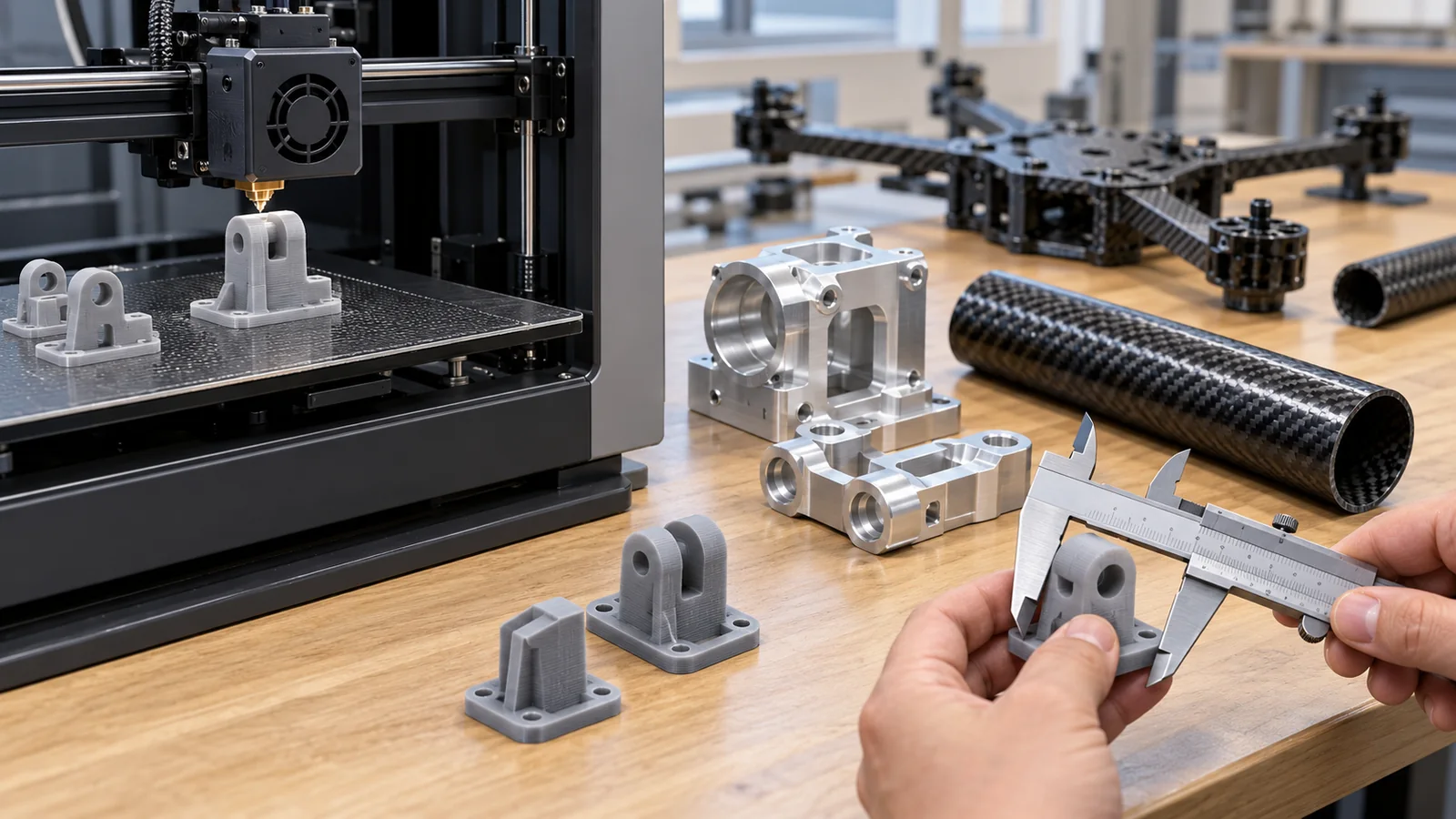
As a numerical example, take the data sheet of nylon 12 formed by laser sintering (SLS), EOS PA 2200. The tensile modulus is 1650 MPa (in X, Y and Z), the tensile strength is 48 MPa in X and Y and 42 MPa in Z, and the strain at break is 18% in X and Y and 4% in Z [Ref. 13] Sourced. Z is the build direction. Strength is only about 12% lower, but the elongation (toughness) falls to about 22% Our calculation (4/18). The deflection temperature (1.8 MPa) is 64 °C in X and 57 °C in Z [Ref. 13] Sourced (Fig. 9).
According to the scope of ISO 75-1, the deflection temperature is for relative comparison between materials, does not necessarily represent a maximum service temperature, and is not intended for design or for predicting long-term endurance at high temperature [Ref. 25] Sourced. Time, load and surface stress differ between the test and a real part. For plastic parts near a motor (the temperatures in Fig. 6), do not compare this value directly with the part temperature; measure the temperature on the actual aircraft (commentary).
The review by Kantaros et al. lists as challenges nozzle wear (abrasive fibers such as carbon or glass), weakness in the build direction (interlayer bonding weaker than in-plane, an anisotropy), variability in quality, and a price for carbon-fiber-filled filaments about 60 to 150% above unreinforced ones [Ref. 12] Sourced. The EOS numbers (Fig. 9) also show elongation changing strongly with build direction. A number that does not state build direction, layer thickness, process conditions and powder history is unusable for design – that is the safe attitude. Resins for 3D printing themselves (photopolymers, powder bed fusion, material extrusion, PEEK) are covered in the polymers explainer on resins for 3D printing.
8. Limits, what we could not confirm, and a summary
What we could not confirm
- E and density of magnesium alloys: we used the apparent E from a NASA internship report and the density of pure magnesium. We could not confirm a primary manufacturer or standards source giving typical AZ31 values
- E/rho of steel: for steel used in gears and shafts we found no primary source giving the elastic modulus, so it is not in Table 1 (the Aubert & Duval steel sheet gives only density and strength)
- Thermal conductivity of CFRP plate (through thickness) and composites, and standard measured values of radio shielding: not confirmed. We have only fiber values and specimen values from specific papers
- Materials of specific models (DJI and others): we did not confirm the materials of any aircraft from an official specification. Only the materials listed in the UR5e data sheet were checked
- Newer data on galvanic contact between CFRP and metals: only the 1983 NASA report. Other environments and material pairs were not checked
- The latest edition of rules on drone structures: we checked the EASA special condition for Light-UAS (December 2020) but did not confirm whether it is the current issue
- ASTM standards: ASTM International’s site states that it prohibits AI use, so we did not open it. No ASTM standard number is given in the text of this article
Summary
- Drone hover power rises with the 1.5th power of mass; a 5% mass cut saves about 7.4% of power (ideal case) Our calculation
- The specific stiffness of metals is about the same (24 to 25). For beams of equal mass, light magnesium bends less Our calculation
- CFRP is outstandingly light and stiff only when aligned with the fibers. A 15 degree turn cuts the modulus to about one third Our calculation
- Papers have measured that CFRP frames shed motor heat poorly and block radio waves Sourced
- For 3D-printed nylon, elongation changes strongly with build direction, and the deflection temperature is not an upper service temperature Sourced
9. How to read the yardsticks and standards
The performance of airframe materials is measured with yardsticks for tension, bending, fatigue, heat and radio. Each depends on “what specimen, in which direction, at what temperature”. For design, aerospace practice is to use not a manufacturer’s typical value but a statistically derived design allowable (MMPDS for metals, CMH-17 for composites and so on) [Ref. 17, 18]. The table lists what we could confirm (checked 25 October 2026).
| What is evaluated | Representative test or data source (name, source) | Standard, regulation or guideline (ISO, EASA, etc.) | Cautions in reading |
|---|---|---|---|
| Metal tension | Typical values in manufacturer data sheets (Kaiser, Aubert & Duval) [2, 3] Sourced | ISO 6892-1:2019 “Metallic materials – Tensile testing – Part 1: Method of test at room temperature” (November 2019, confirmed in 2025) [19] Sourced. Design allowables: MMPDS (the 2026 edition is announced; a paid handbook) [18] Sourced | A typical value is not a guaranteed value. Keep it apart from statistical allowables |
| Plastic tension and bending | EOS data sheet (X, Y and Z directions) [13] Sourced | ISO 527-1:2019 (general principles of tensile testing, confirmed in 2025) [20] Sourced. ISO 178:2019 (bending; a revision, ISO/DIS 178, is in preparation) [24] Sourced Not yet confirmed | Values change with build direction and moisture state |
| Heat resistance of plastics | Deflection temperature (PA 2200: 64 °C in X and 57 °C in Z at 1.8 MPa) [13] Sourced | ISO 75-1:2020 “Plastics – Determination of temperature of deflection under load – Part 1: General test method” (confirmed in 2026) [25] Sourced | For comparing materials; not for design or for predicting long-term endurance (the standard’s wording) |
| Tension and bending of fiber-reinforced plastics | Typical Hexcel and Toray data-sheet values (unidirectional, about 60% fiber volume) [6, 7] Sourced | ISO 527-5:2021 (tension of unidirectional materials) [21] Sourced. ISO 527-4 (multidirectional materials; the 2021 edition is withdrawn and a 2023 edition is shown as the new version) [22] Sourced. ISO 14125:1998 (bending; confirmed in 2024) [23] Sourced. Methodology for design data: CMH-17 [17] Sourced | Values change with fiber direction, lay-up and fiber volume. Do not mix fiber values with composite values |
| 3D-printed parts | Manufacturer data sheets (by build direction) [13] Sourced | ISO/ASTM 52900:2021 “Additive manufacturing – General principles – Fundamentals and vocabulary” (terminology standard, confirmed in 2025) [26] Sourced. The additive-manufacturing volume of CMH-17 (Volume 7, under revision) [17] Sourced Not yet confirmed | Data that do not state build conditions are unusable |
| Performance as a robot | Manufacturer data sheet (UR5e: payload, pose repeatability) [15] Sourced | ISO 9283:1998 “Manipulating industrial robots – Performance criteria and related test methods” (confirmed in 2021, now under review) [27] Sourced Not yet confirmed. ISO 10218-1:2025 (safety of industrial robots) [28] Sourced | Not a materials evaluation; standards for whole-robot performance and safety |
| Drone structure and materials | Measurements in papers (frame material with temperature and vibration [8, 9]; radio [10, 11]) Sourced | EASA “Special Condition Light Unmanned Aircraft Systems – Medium Risk”, SC Light-UAS Medium Risk 01 (Issue 01, 17 December 2020, Final): Light-UAS.2240 (structural durability), 2250 (design and construction principles), 2260 (materials and processes: “adequate and reproducible properties and performance”) [16] Sourced. Whether this is the latest issue is not confirmed | This special condition does not set specific material values (within what we checked). The key is “reproducible properties” |
| Heat and radio (airframe materials) | Measurements in each paper (different specimens and conditions) [8 to 11] Sourced | Not confirmed | We could not confirm a common test method. Read the conditions of each paper |
Numbers, titles and status of standards were checked on the official ISO pages (25 October 2026). The standard texts are paid, so we stay with the scope statements. The arrangement of the table is Our calculation. Because ASTM states that it prohibits AI use, we do not treat ASTM standard numbers in this article.
Cautions in reading (for materials engineers)
- Data-sheet values are not guaranteed design values: the Toray data sheet states that its values are lot averages for reference and not for specification [Ref. 7]. Aubert & Duval also say theirs are typical values, not guarantees [Ref. 3]
- A laboratory result is about one aircraft: Milenin’s temperature and vibration results come from one group’s particular designs. Do not generalize them to other aircraft or flying styles
- Standards are mostly voluntary: ISO standards generally become binding only when cited in law or contract (commentary). An EASA special condition applies within the operations and certification it covers
- Standards under revision or review can change: ISO 178 and ISO 9283, for example, are under revision or review as of the check date Not yet confirmed
10. Glossary
- Elastic modulus (Young’s modulus)
- A measure of stiffness when pulled. Larger means it deforms less.
- Density
- Mass per cubic centimeter, in g/cm3.
- Specific stiffness
- Elastic modulus divided by density (E/rho). A guide to stiffness per unit mass.
- Yield strength
- The stress at which a material starts to deform permanently.
- Fatigue
- Failure under repeated loads even at stresses below the yield strength.
- Fatigue endurance limit
- The stress below which a material is expected to survive a nearly unlimited number of cycles.
- CFRP
- Carbon-fiber-reinforced plastic: a composite of carbon fiber in resin.
- Unidirectional material
- A composite with all fibers in one direction. Its properties differ greatly by direction.
- Anisotropy
- Properties that differ with direction.
- Quasi-isotropic laminate
- A lay-up with fibers at 0/45/-45/90 degrees, giving similar stiffness in every in-plane direction.
- Fiber volume fraction
- The share of the composite’s volume taken up by fibers.
- Laminate
- A plate made by stacking and curing layers of fibers.
- Galvanic corrosion
- Corrosion that speeds up in one of two different conductors in contact in an electrolyte.
- Thermal conductivity
- How readily heat passes through a material, in W/(m·K).
- Deflection temperature under load
- The temperature at which a plastic deflects by a set amount under a set load. For comparing materials.
- Transmission loss (dB)
- How much a material weakens radio waves passing through. -3 dB is about half the power.
- SLS (laser sintering)
- A 3D-printing method that fuses plastic powder with a laser.
- PA12 (nylon 12)
- A polyamide resin used in 3D printing.
- Hover
- A drone holding still in the air.
- Design allowable
- A statistically derived, conservative strength usable in design. Maintained by MMPDS and CMH-17.
11. References (primary sources)
- Bauersfeld L., Scaramuzza D. “Range, Endurance, and Optimal Speed Estimates for Multicopters”, IEEE Robotics and Automation Letters (2022; arXiv:2109.04741; hover-power equation (5) checked) – https://arxiv.org/abs/2109.04741
- Kaiser Aluminum “Rod & Bar Alloy 6061 Technical Data” (data sheet KA-RBH-6061-8.10) – https://online.kaiseraluminum.com/depot/PublicProductInformation/Document/1025/Kaiser_Aluminum_6061_Rod_and_Bar.pdf
- Aubert & Duval “Titanium Alloy TA6V ELI” (data sheet) – https://www.aubertduval.com/wp-content/uploads/2024/12/TA6V-ELI_GB.pdf
- Aroh J. (NASA Kennedy Space Center) “Magnesium Alloys for Space Hardware Design” (internship final report, 2017; tensile-test tables checked) – https://ntrs.nasa.gov/citations/20170011677
- NIST “X-Ray Mass Attenuation Coefficients: Table 1, elemental data (density)” (checked 25 October 2026) – https://physics.nist.gov/PhysRefData/XrayMassCoef/tab1.html
- Hexcel “HexPly 8552 Epoxy matrix Product Data Sheet” (2023 edition; tables for UD carbon prepregs AS4 and IM7 checked) – https://hexcel.com/wp-content/uploads/2025/12/HexPly_8552_eu_DataSheet1.pdf
- Toray Composite Materials America “TORAYCA T700S Standard Modulus Carbon Fiber Data Sheet” (Rev. 24 November 2025) – https://www.toraycma.com/wp-content/uploads/T700S-Data-Sheet.pdf
- Milenin A. “Effects of FPV Drone Frame Materials on Thermal Conditions of Motors Under Extreme Payloads: Experimental and Numerical Analysis”, Processes 13, 3034 (2025), DOI 10.3390/pr13103034 (open access; checked at abstract level) – https://doi.org/10.3390/pr13103034
- Milenin A. “Experimental Analysis of an AZ31 Magnesium Alloy Structural FPV Drone Frame: Comparison with Aluminum and Carbon Fiber”, Processes 14, 1361 (2026), DOI 10.3390/pr14091361 (open access; checked at abstract level) – https://doi.org/10.3390/pr14091361
- Wahyudi et al. “Analysis of unmanned aerial vehicle airframe materials on circularly polarized antenna radiation characteristics”, Bulletin of Electrical Engineering and Informatics 14(4), 2649-2661 (2025), DOI 10.11591/eei.v14i4.8010 (open access; checked at abstract level) – https://doi.org/10.11591/eei.v14i4.8010
- Merkli et al. “Characterizing UAV airframe effects on mobile-band RF and EMF measurements under controlled anechoic conditions”, International Journal of Microwave and Wireless Technologies 18(4), 632-646 (2026), DOI 10.1017/S175907872610350X (checked at abstract level) – https://doi.org/10.1017/S175907872610350X
- Kantaros A., Drosos C., Papoutsidakis M. “Composite Filament Materials for 3D-Printed Drone Parts: Advancements in Mechanical Strength, Weight Optimization and Embedded Electronics”, Materials 18, 2465 (2025), DOI 10.3390/ma18112465 (review; open access; main text checked) – https://doi.org/10.3390/ma18112465
- EOS “PA 2200 Material Data Sheet” (process Balance, 120 µm layers; as of 23 October 2026) – https://www.eos.info/polymer-solutions/polymer-materials/data-sheets/mds-pa-2200
- Danford M. D., Higgins R. H. (NASA) “Galvanic coupling between D6AC steel, 6061-T6 aluminum, Inconel 718 and graphite-epoxy composite material: Corrosion occurrence and prevention” (1983; checked at abstract level) – https://ntrs.nasa.gov/citations/19840005195
- Universal Robots “UR5e Specification” (data sheet, August 2023 edition) – https://www.universal-robots.com/media/1807465/ur5e_e-series_datasheets_web.pdf
- EASA “Special Condition Light Unmanned Aircraft Systems – Medium Risk”, Doc. No. SC Light-UAS Medium Risk 01, Issue 01 (17 December 2020, Final) – https://www.easa.europa.eu/sites/default/files/dfu/special_condition_sc_light-uas_medium_risk_01.pdf
- CMH-17 “Composite Materials Handbook-17” (description on the official site checked; 25 October 2026) – https://www.cmh17.org
- MMPDS (Battelle) “Metallic Materials Properties Development and Standardization (MMPDS)” (description on the official site checked; the site announces the release of MMPDS-2026; 25 October 2026) – https://www.mmpds.org/
- ISO “ISO 6892-1:2019 Metallic materials – Tensile testing – Part 1: Method of test at room temperature” (ISO standard page) – https://www.iso.org/standard/78322.html
- ISO “ISO 527-1:2019 Plastics – Determination of tensile properties – Part 1: General principles” (ISO standard page) – https://www.iso.org/standard/75824.html
- ISO “ISO 527-5:2021 Plastics – Determination of tensile properties – Part 5: Test conditions for unidirectional fibre-reinforced plastic composites” (ISO standard page) – https://www.iso.org/standard/80370.html
- ISO “ISO 527-4:2021 Plastics – Determination of tensile properties – Part 4: Test conditions for isotropic and orthotropic fibre-reinforced plastic composites” (ISO standard page; shown as withdrawn, with ISO 527-4:2023 as the new version) – https://www.iso.org/standard/80369.html
- ISO “ISO 14125:1998 Fibre-reinforced plastic composites – Determination of flexural properties” (ISO standard page) – https://www.iso.org/standard/23637.html
- ISO “ISO 178:2019 Plastics – Determination of flexural properties” (ISO standard page) – https://www.iso.org/standard/70513.html
- ISO “ISO 75-1:2020 Plastics – Determination of temperature of deflection under load – Part 1: General test method” (ISO standard page) – https://www.iso.org/standard/77576.html
- ISO “ISO/ASTM 52900:2021 Additive manufacturing – General principles – Fundamentals and vocabulary” (ISO standard page) – https://www.iso.org/standard/74514.html
- ISO “ISO 9283:1998 Manipulating industrial robots – Performance criteria and related test methods” (ISO standard page) – https://www.iso.org/standard/22244.html
- ISO “ISO 10218-1:2025 Robotics – Safety requirements – Part 1: Industrial robots” (ISO standard page) – https://www.iso.org/standard/73933.html
- Aubert & Duval “Steel 819B (36NiCrMo16)” (data sheet) – https://www.aubertduval.com/wp-content/uploads/2024/12/819B-ts_GB.pdf
12. Claim-to-source audit
| Claim in the text | Basis | Category |
|---|---|---|
| Hover power is proportional to the 1.5th power of mass (the momentum-theory equation) | Bauersfeld L., Scaramuzza D. Reference 1 https://arxiv.org/abs/2109.04741 | Sourced |
| A 5% mass cut gives about 7.4% less power (0.95^1.5 = 0.926) and about 8.0% more flight time in theory; the gravity torque of a 5 kg link at 0.5 m is about 24.5 N·m, and 19.6 N·m at 4 kg (about 20% less) | Our calculation (inputs are published values from the sources) Reference 1 https://arxiv.org/abs/2109.04741 | Our calculation |
| UR5e: payload 5 kg, reach 850 mm, mass 20.6 kg including cable, materials “aluminum, plastic, steel”, pose repeatability +/-0.03 mm per ISO 9283 | Universal Robots Reference 1 https://www.universal-robots.com/media/1807465/ur5e_e-series_datasheets_web.pdf | Sourced |
| 5 / 20.6 = about 0.24 | Our calculation (inputs are published values from the sources) Reference 1 https://www.universal-robots.com/media/1807465/ur5e_e-series_datasheets_web.pdf | Our calculation |
| 6061-T6: density 2.70 Mg/m3, E 68.3 GPa, yield 276 MPa, tensile 310 MPa, elongation 17%, fatigue endurance limit 97 MPa (5 x 10^8 cycles, R.R. Moore type), thermal conductivity 167 W/(m·K) | Kaiser Aluminum Reference 1 https://online.kaiseraluminum.com/depot/PublicProductInformation/Document/1025/Kaiser_Aluminum_6061_Rod_and_Bar.pdf | Sourced |
| Ti-6Al-4V ELI annealed: density 4.42, E 110 GPa, yield 790 MPa, tensile 860 MPa, elongation 10% (typical values) | Aubert & Duval Reference 1 https://www.aubertduval.com/wp-content/uploads/2024/12/TA6V-ELI_GB.pdf | Sourced |
| Mean of AZ31 tensile tests: E about 42.0 GPa (apparent), tensile 294 MPa, yield 206 MPa, elongation 15% (NASA KSC internship report) | Aroh J. (NASA Kennedy Space Center) Reference 1 https://ntrs.nasa.gov/citations/20170011677 | Sourced |
| Density of magnesium 1.740 g/cm3 (element) | NIST Reference 1 https://physics.nist.gov/PhysRefData/XrayMassCoef/tab1.html | Sourced |
| IM7/8552 UD: 0 deg E 164 GPa, 90 deg E 12 GPa, 0 deg tensile strength 2724 MPa, 90 deg tensile strength 64 MPa, laminate density 1.57 g/cm3, fiber volume 57.7% | Hexcel Reference 1 https://hexcel.com/wp-content/uploads/2025/12/HexPly_8552_eu_DataSheet1.pdf | Sourced |
| T700S: fiber 4,900 MPa, 230 GPa, 1.80 g/cm3; composite (60% fiber) 2,860 MPa, 134 GPa; 90 deg tensile strength 81 MPa; electrical resistivity 1.6 x 10^-3 Ω·cm; thermal conductivity 0.096 J/(cm·s·°C); data are for reference, not for specification | Toray Composite Materials America Reference 1 https://www.toraycma.com/wp-content/uploads/T700S-Data-Sheet.pdf | Sourced |
| E/rho (25.3, 24.9, 24.1, 104.5, 7.6, 1.8), E/rho^2 (9.4, 5.6, 13.9, 66.5, 4.9, 1.9, 25.4), ratios (about 1.5x, 0.6x, 2.7x, 7x), 81/2860 = about 1/35, about 1/3 at 15 degrees, 14.0 GPa at 45 degrees, quasi-isotropic 62.7 GPa (about 38% of 0 degrees) | Our calculation (inputs are published values from the sources) Reference 1 https://hexcel.com/wp-content/uploads/2025/12/HexPly_8552_eu_DataSheet1.pdf Reference 2 https://www.toraycma.com/wp-content/uploads/T700S-Data-Sheet.pdf | Our calculation |
| Derivation of E/rho^2 (cantilever, square section, fixed mass and length) | Commentary (reading not found in a source); our own organization, not the view of any institution | Commentary |
| Steel 819B: yield strength 850 MPa and 1400 MPa depending on tempering, density 7.8 (no elastic modulus given) | Aubert & Duval Reference 1 https://www.aubertduval.com/wp-content/uploads/2024/12/819B-ts_GB.pdf | Sourced |
| Corrosion when 6061-T6 aluminum is coupled to graphite-epoxy in salt water, and prevention by coating (Danford and Higgins, 1983) | Danford M. D., Higgins R. H. (NASA) Reference 1 https://ntrs.nasa.gov/citations/19840005195 | Sourced |
| Endurance limit of 97 MPa is about 35% of yield and about 31% of tensile strength | Our calculation (inputs are published values from the sources) Reference 1 https://online.kaiseraluminum.com/depot/PublicProductInformation/Document/1025/Kaiser_Aluminum_6061_Rod_and_Bar.pdf | Our calculation |
| 7-inch aircraft with the lower plate swapped between CFRP and aluminum 6061-T6: no load 37 to 44 °C; with 20 N, CFRP over 90 °C and aluminum under 60 °C, about 30 °C lower; fewer and lower-frequency resonances for aluminum | Milenin A. Reference 1 https://doi.org/10.3390/pr13103034 | Sourced |
| Cast AZ31, aluminum 6061-T6 and CFRP frames: mean motor temperature 51.8 / 50.3 / 77.5 °C (2 kg payload); AZ31 vibration power 49% lower than aluminum; resonance peaks | Milenin A. Reference 1 https://doi.org/10.3390/pr14091361 | Sourced |
| Thermal conductivity of carbon fiber (the fiber itself) 9.6 W/(m·K) is about 1/17 of aluminum (167) | Our calculation (inputs are published values from the sources) Reference 1 https://online.kaiseraluminum.com/depot/PublicProductInformation/Document/1025/Kaiser_Aluminum_6061_Rod_and_Bar.pdf Reference 2 https://www.toraycma.com/wp-content/uploads/T700S-Data-Sheet.pdf | Our calculation |
| E-glass composite -1.5 dB and carbon-fiber (twill) composite -31.24 dB (5.3 GHz, specimens of the same size and thickness) | Wahyudi et al. Reference 1 https://doi.org/10.11591/eei.v14i4.8010 | Sourced |
| -1.5 dB = 70.8%, -31.24 dB = 0.075%, ratio about 940x | Our calculation (inputs are published values from the sources) Reference 1 https://doi.org/10.11591/eei.v14i4.8010 | Our calculation |
| Receive antenna on a carbon-fiber airframe: increasing the distance to the frame reduces the difference by about 1 to 1.5 dB (700 to 3500 MHz, mostly under 3 dB, that aircraft only) | Merkli et al. Reference 1 https://doi.org/10.1017/S175907872610350X | Sourced |
| Use of carbon-fiber-filled filaments for drone parts, nozzle wear, weak interlayer bonding, price about 60 to 150% higher, injection molding used for consumer drones (review) | Kantaros A., Drosos C., Papoutsidakis M. Reference 1 https://doi.org/10.3390/ma18112465 | Sourced |
| PA 2200 Balance: modulus 1650 MPa (X, Y, Z), tensile strength 48/48/42 MPa, strain at break 18/18/4%, density 0.93, deflection temperature (1.8 MPa) 64/57 °C, (0.45 MPa) 157/145 °C, test methods ISO 527-1/-2, 178, 75-1/-2 | EOS Reference 1 https://www.eos.info/polymer-solutions/polymer-materials/data-sheets/mds-pa-2200 | Sourced |
| Strength about 12% lower in Z (42/48) and strain at break about 22% (4/18) | Our calculation (inputs are published values from the sources) Reference 1 https://www.eos.info/polymer-solutions/polymer-materials/data-sheets/mds-pa-2200 | Our calculation |
| Deflection temperature is for relative comparison, does not necessarily represent a maximum service temperature, and is not for design or long-term endurance prediction (scope of ISO 75-1) | ISO Reference 1 https://www.iso.org/standard/77576.html | Sourced |
| EASA SC Light-UAS Medium Risk 01 (Issue 01, 17 December 2020, Final): Light-UAS.2240, 2250, 2260 | EASA Reference 1 https://www.easa.europa.eu/sites/default/files/dfu/special_condition_sc_light-uas_medium_risk_01.pdf | Sourced |
| MMPDS covers statistical design allowables for metals; CMH-17 covers methods for composite data and an additive-manufacturing volume (Volume 7) | CMH-17; MMPDS (Battelle) Reference 1 https://www.cmh17.org Reference 2 https://www.mmpds.org/ | Sourced |
| ISO 6892-1:2019 (November 2019, confirmed in 2025) | ISO Reference 1 https://www.iso.org/standard/78322.html | Sourced |
| ISO 527-1:2019 (July 2019, confirmed in 2025) | ISO Reference 1 https://www.iso.org/standard/75824.html | Sourced |
| ISO 527-5:2021 (unidirectional materials), and the withdrawal of ISO 527-4:2021 with a 2023 edition | ISO; ISO Reference 1 https://www.iso.org/standard/80370.html Reference 2 https://www.iso.org/standard/80369.html | Sourced |
| ISO 14125:1998 (confirmed in 2024) and ISO 178:2019 (revision ISO/DIS 178 in preparation) | ISO; ISO Reference 1 https://www.iso.org/standard/23637.html Reference 2 https://www.iso.org/standard/70513.html | Sourced |
| ISO/ASTM 52900:2021 (confirmed in 2025) | ISO Reference 1 https://www.iso.org/standard/74514.html | Sourced |
| ISO 9283:1998 (confirmed in 2021, now under review) and ISO 10218-1:2025 | ISO; ISO Reference 1 https://www.iso.org/standard/22244.html Reference 2 https://www.iso.org/standard/73933.html | Sourced |
| Nature of the figures: Figures 2 to 7 and 9 are concept diagrams or charts with our calculation made for explanation; Figures 1 and 8 are frames for AI-generated images. Example materials per part (other than the UR5e “aluminum, plastic, steel”), why the specific stiffness of metals is similar, design ideas for heat removal from CFRP frames | Commentary (reading not found in a source); our own organization, not the view of any institution | Commentary |
| Primary typical values for magnesium, the elastic modulus of steel, thermal conductivity of composites, materials of specific models, the latest edition of rules and ASTM standards | Could not be confirmed in primary sources within the scope of this article, so it is not stated | Commentary |
Last updated: 25 October 2026 / Sources are limited to primary sources (manufacturer data sheets, peer-reviewed papers, NASA reports, official ISO and EASA pages). Numbers are typical data-sheet values or values from specific papers’ conditions, not guaranteed design values. Primary typical values for magnesium alloys, the elastic modulus of steel, thermal conductivity of composites, materials of specific models and the latest edition of rules could not be confirmed, so they are not stated. Figures 2 to 7 and 9 are concept diagrams or charts with our calculation made for explanation (Figures 6 and 9 use data-sheet and paper values); Figures 1 and 8 are frames for AI-generated images (no image placed yet).